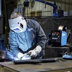
How to Prevent Common Causes of Poor Welding Wire Feeding
Poor wire feeding is a common problem encountered in many welding operations. Unfortunately, it can be a significant source of downtime and lost productivity — not to mention cost.
Poor or erratic wire feeding can lead to premature failure of consumables, burnbacks, bird-nesting and more. To simplify troubleshooting, it’s best to look for issues in the wire feeder first and move toward the front of the gun to the consumables.
Finding the cause of the problem can sometimes be complicated, however, wire feeding issues often have simple solutions.
What’s happening with the feeder?
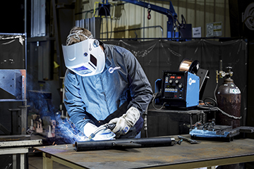
When poor wire feeding occurs, it can be related to several components in the wire feeder.
1. If the drive rolls don’t move when you pull the trigger, check to see if the relay is broken. Contact your feeder manufacturer for assistance if you suspect this is the issue. A faulty control lead is another possible cause. You can test the control lead with a multimeter to determine if a new cable is needed.
2. An incorrectly installed guide tube and/or the wrong wire guide diameter may be the culprit. The guide tube sits between the power pin and the drive rolls to keep the wire feeding smoothly from the drive rolls into the gun. Always use the proper size guide tube, adjust the guides as close to the drive rolls as possible and eliminate any gaps in the wire path.
3. Look for poor connections if your MIG gun has an adapter that connects the gun to the feeder. Check the adapter with a multimeter and replace it if it’s malfunctioning.
Take a look at the drive rolls
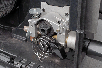
is the wrong size for the wire being used.
Using the wrong size or style of welding drive rolls can cause poor wire feeding. Here are some tips to avoid problems.
1. Always match the drive roll size to the wire diameter.
2. Inspect drive rolls every time you put a new spool of wire on the wire feeder. Replace as necessary.
3. Choose the style of drive roll based on the wire you are using. For example, smooth welding drive rolls are good for welding with solid wire, whereas U-shaped ones are better for tubular wires — flux-cored or metal-cored.
4. Set the proper drive roll tension so there is sufficient pressure on the welding wire to feed it through smoothly.
Check the liner
Several issues with the welding liner can lead to erratic wire feeding, as well as burnbacks and bird-nesting.
1. Be sure the liner is trimmed to the correct length. When you install and trim the liner, lay the gun flat, making certain the cable is straight. Using a liner gauge is helpful. There are also consumable systems available with liners that don’t require measuring. They lock and concentrically align between the contact tip and power pin without fasteners. These systems provide error-proof liner replacement to eliminate wire feeding problems.
2. Using the wrong size welding liner for the welding wire often leads to wire feeding problems. Select a liner that is slightly larger than the diameter of the wire, as it allows the wire to feed smoothly. If the liner is too narrow, it will be difficult to feed, resulting in wire breakage or bird-nesting.
3. Debris buildup in the liner can impede wire feeding. It can result from using the wrong welding drive roll type, leading to wire shavings in the liner. Microarcing can also create small weld deposits inside the liner. Replace the welding liner when buildup results in erratic wire feeding. You can also blow compressed air through the cable to remove dirt and debris when you change over the liner.
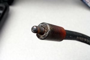
Monitor for contact tip wear
Welding consumables are a small part of the MIG gun, but they can affect wire feeding — particularly the contact tip. To avoid problems:
1. Visually inspect the contact tip for wear on a regular basis and replace as necessary. Look for signs of keyholing, which occurs when the bore in the contact tip becomes oblong over time due to the wire feeding through it. Also look for spatter buildup, as this can cause burnbacks and poor wire feeding.
2. Consider increasing or decreasing the size of contact tip you are using. Try going down one size first, which can help promote better control of the arc and better feeding.
Additional thoughts
Poor wire feeding can be a frustrating occurrence in your welding operation — but it doesn’t have to slow you down for long. If you still experience problems after inspecting and making adjustments from the feeder forward, take a look at your MIG gun. It is best to use the shortest cable possible that can still get the job done. Shorter cables minimize coiling that could lead to wire feeding issues. Remember to keep the cable as straight as possible during welding, too. Combined with some solid troubleshooting skills, the right gun can keep you welding for longer.
November 11, 2019 In September 2017, Tregaskiss entered into a Master Distribution Agreement with DINSE GmbH to provide best-in-class robotic water-cooled MIG guns to the North American market under the Tregaskiss® by DINSE™ brand name. After many discussions between Tregaskiss and DINSE, we have made an amicable and mutual decision to end our business relationship. This notice is to officially announce that Tregaskiss will discontinue sales of Tregaskiss® by DINSE™ Robotic Water-Cooled MIG Guns, parts and consumables as of April 30, 2020. Until that termination date, Tregaskiss will not accept orders from new customers but will continue to provide product to support existing customers. Details of affected part numbers can be accessed here. When current Tregaskiss by DINSE Robotic Water-Cooled MIG Guns eventually require replacement, end users have two options: After April 30, 2020, please obtain all replacement parts and consumables from the relevant manufacturer. Please contact your local representative with any questions regarding these changes.
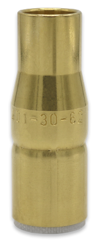
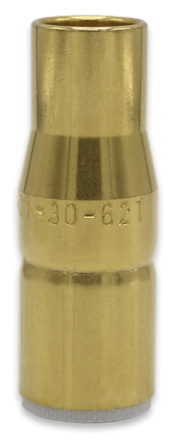
April 3, 2020 Tregaskiss is proud to announce the addition of two new nozzles to the AccuLock™ R consumables offering. Only slightly larger than 1/2″ bore nozzles, these 5/8″ bore nozzles offer almost the same weld access while still providing the clearance needed for reliable gas flow and reaming to the gas holes. These new nozzles are also now configurable on TOUGH GUN® TA3 and CA3 robotic air-cooled MIG guns. Learn more about AccuLock R consumables, or configure your robotic MIG gun online.
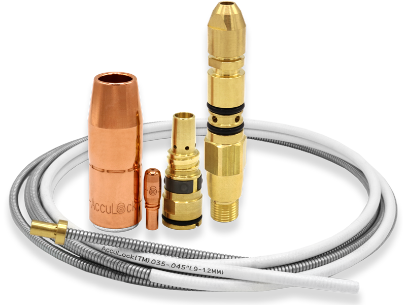
BEECHER, Ill. February 19, 2020 – Bernard has expanded its AccuLock™ S consumables system to include additional diffuser and nozzle types and sizes, as well as new contact tip options. The large AccuLock S consumables offering now features a new slip-on diffuser, along with a copper 3/8-inch bore tapered nozzle. Bernard has also added two new diffusers that allow small AccuLock S consumables to be installed easily, including thread-on and slip-on versions — plus compatible brass and copper nozzles with 5/8- and 1/2-inch bores and brass nozzles with 3/8-inch bores. A variety of tip recesses are available within the selection of nozzles. In the case of the small or large AccuLock S consumable offering, the same nozzle can install onto either a thread-on or slip-on diffuser. New tapered ‘TT’ series contact tips (0.350-inch O.D.) are available to accommodate wire diameters ranging from 0.023 to 1/16 inch and are compatible with both small and large AccuLock S diffusers and nozzles. The ‘TT’ series contact tips pair with tapered-profile nozzles to provide the same tip recess and better weld joint access. Like other contact tips in the system, the ‘TT’ series contact tips feature coarse threads that easily mate with the gas diffuser to reduce the risk of cross-threading and to speed replacement. The AccuLock S consumables, introduced in early 2019, were designed to reduce downtime, troubleshooting and rework associated with errors in liner trim length and erratic wire feeding. The system concentrically aligns the liner with the power pin and contact tip, locking it in place for a flawless wire feeding path. Welders don’t need to measure the liner during installation or replacement — they simply cut the liner flush with the back of the power pin for perfect liner trimming, every time. In addition to contact tips, nozzles and gas diffusers, the AccuLock S consumables require an AccuLock S-specific liner, power pin and power pin cap. # # #
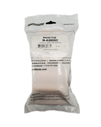
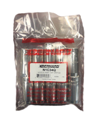
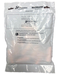
February 14, 2020 Tregaskiss® and Bernard® branded nozzles are currently packaged in a variety of bag sizes and styles. We will begin standardizing on a single size and style bag for all Tregaskiss and Bernard nozzles over the coming months as a running change that takes place as existing inventory is depleted. 5″ x 8″ (white) 8″ x 10″ (white) 6″ x 8″ (clear) 8″ x 10″ (white) (subject to change depending on volume changes)
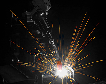
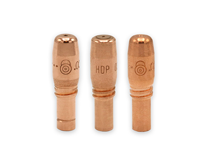
In many cases, equipment-based solutions can be a means to gain success in the robotic welding operation. They can mitigate costly risks and eliminate issues that lead to inefficiencies. And often, these issues are related to a small but significant part of the robotic welding process — the welding consumables. Changing over consumables can be a time-consuming part of maintaining the welding cell, especially if it is done multiple times during a shift. Changeover can also negatively impact productivity and quality if the consumables are installed incorrectly. Unfortunately, given the industry’s current lack of skilled welders, that may be a common occurrence. Welders simply have less experience with proper installation processes. To address this problem, many companies tend to spend more time and money on training and troubleshooting. They may even have to find workarounds to problems in the weld cell as employees get up to speed. All of this occupies resources. Welding consumables — the contact tip, gas diffuser and nozzle — can be a major source of downtime in robotic welding operations, unplanned or planned. During installation, cross-threading of contact tips by less experienced welders is a common occurrence that can result in unplanned downtime. Cross-threading leads to multiple problems beyond the lost productivity for contact tip changeover. First, it can negatively affect tool center point (TCP), causing the robot to weld off-seam and create quality issues like lack of fusion or poor penetration. Personnel overlooking the robotic welding cell then need to stop production to address rework and/or scrap the part. Cross-threading can also create a keyhole, or uneven wear, in the bore of the contact tip. A keyhole the size of only half the diameter of the wire can result in the robot welding off-seam. Many times, a cross-threaded contact tip will stick inside the welding gas diffuser. Without another gas diffuser readily available, the operator has to make a trip to the tool crib for a new one. Meanwhile the robot is offline and not producing parts. Plus, a company incurs costs for both the contact tip and the diffuser’s replacement. Companies that invest in power sources with a pulsed waveform capability — particularly in the automotive industry — often schedule planned downtime. Pulse waveforms improve productivity and quality by increasing travel speeds, providing a more consistent arc and reducing spatter. However, the pulsing action of the arc electrically and mechanically erodes the contact tip, leading to faster wear. It is necessary to plan downtime as a preemptive strike against contact tip failures before the chance of associated weld quality issues arise. Both unplanned and planned downtime cost money and occupy available labor for non-value-added activities — tasks that don’t support throughput and productivity. There is a new welding consumables technology that can help. To address the issue of cross-threaded contact tips, Tregaskiss designed its AccuLock™ R consumables. The design is intended to support higher throughput, provide a long service life and ensure good weld quality. The AccuLock contact tip features a long tail that concentrically aligns within the diffuser before the threads engage. The threads are also coarse, so they require minimal rotations to install. This design virtually eliminates the risk of cross-threading and provides three key benefits to the robotic welding operation: The contact tips also have greater mass at the front compared to other designs, along with a taper that mates securely with the gas diffuser. The tapered surfaces ensure optimal conductivity, reduce heat and keep the consumables locked in place. These features — combined with the fact that 60% of the contact tip is buried in the diffuser, away from the heat of the arc — make the consumables last longer. Extending the product life means there is less need for changeovers. AccuLock R consumables can also address the accelerated wear of contact tips caused by pulsed waveforms. In addition to offering the contact tips in copper and chrome zirconium, Tregaskiss has an AccuLock HDP option. The HDP contact tips last more than 10 times longer than copper tips in pulsed MIG welding applications. As a result, companies can reduce unplanned downtime for contact tip changeover — and make those changeovers faster because of the easy-to-install design. AccuLock R consumables can be implemented easily. Switching from many other consumables typically doesn’t affect TCP or robotic programming; however, it is best to consult directly with Tregaskiss to confirm this is the case. For companies that have both robotic welding and semi-automatic welding operations, the AccuLock R consumables can simplify complex inventories. The contact tips are part of a Common Consumable Platform™ and can be used across a wide range of Tregaskiss® robotic and fixed automatic MIG guns, as well as with Bernard® semi-automatic MIG guns (ranging from 200 to 600 amps). This common contact tip can reduce inventory costs and lessens the opportunity for operators to install the wrong consumable. The AccuLock R gas diffuser also has a blue o-ring to distinguish it from other diffusers. When companies find equipment solutions, like the AccuLock R consumables, that help reduce troubleshooting and downtime in their robotic welding operations, opportunities can increase. The ability to improve productivity and quality is at the forefront of those. But there may also be more time available to optimize the weld cell, make positive changes to workflow or material handling and seek out cost savings.In some cases, companies may also uncover issues in the weld cell that were previously masked by frequent contact tip changeovers. Now, however, there is more time address those to generate greater efficiencies in the operation. In short, with the right consumables, there is more time to focus on reaching improvement targets and increasing throughput — and on implementing training that can help achieve those goals.
December 2, 2019 Effective November 15, 2019, the TOUGH GUN® TT3E (Ethernet) reamer is now running updated firmware and software. The ARGEE software has been updated from version 4.0 to 4.1, and the firmware from version 3.5 to 3.6. For more information or to access software files, please visit the TOUGH GUN TT3E reamer webpage.
WINDSOR, Ontario (November 14, 2019) – Tregaskiss has designed its new AccuLock™ R consumables system to virtually eliminate cross-threading issues and offers AccuLock HDP contact tips as an option within the series to extend tip life by 10 times or more in certain pulsed welding applications. The consumables can help to reduce both unplanned and planned downtime in robotic MIG welding applications. By increasing efficiency, AccuLock R consumables help companies achieve annual cost reduction and throughput goals — with minimal risk or effort. They are ideal for applications in the automotive, fabrication and manufacturing industries. For companies challenged with a shortage of experienced welding operators, reducing the need for replacement of the AccuLock R consumables means fewer human interactions within the welding cell and fewer opportunities for errors during installation. The coarse threads on the contact tip are responsible for virtually eliminating the risk of cross-threading and a long contact tip tail concentrically aligns within the diffuser prior to thread engagement, ensuring quick, accurate replacement. Eliminating cross-threading issues allows companies to spend less time troubleshooting and more time focused on weld quality and productivity initiatives. The Tregaskiss® AccuLock R and Bernard® AccuLock S consumables share a common contact tip available for welding wire sizes ranging from 0.023 to 1/8 inch. This common consumables platform™ simplifies inventory and reduces the chance of mistakes during changeover. The consumables are compatible with front-loading QUICK LOAD® liners from Tregaskiss, as well as TOUGH GUN® CA3 and TA3 robotic MIG guns and Tregaskiss air-cooled fixed automation MIG guns. Current users of Tregaskiss® TOUGH LOCK® consumables or other contact tips and diffusers can, in most cases, easily change to AccuLock R consumables without affecting the tool center point (TCP) or needing to reprogram the robot.
October 23, 2019 Tregaskiss is pleased to announce the launch of new AccuLock™ R consumables, a system designed to maximize throughput and efficiency with minimal risk and effort. AccuLock contact tips last longer and are virtually impossible to cross-thread. The long contact tip tail concentrically aligns the tip within the diffuser prior to thread engagement, and this coupled with the tip’s coarse thread ensures quick, accurate replacement without cross-threading. An upgrade to AccuLock HDP contact tips can extend life by 10x or more in pulse welding applications. You can easily switch from TOUGH LOCK® and other consumables to AccuLock R consumables with no impact to tool center point (TCP), making this upgrade low effort, low risk, and high payoff. Plus, Tregaskiss AccuLock R consumables and Bernard® AccuLock S consumables share a common contact tip, so you can benefit from the reduced costs and simplified inventory of a common consumable platform™ if you have a combination of robotic and semi-automatic MIG guns in your facility. Reduce troubleshooting, downtime and rework with these new consumables. Learn more about Tregaskiss® AccuLock™ R consumables.
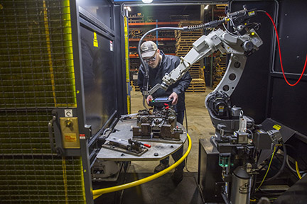
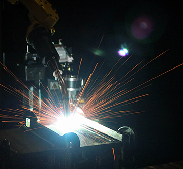
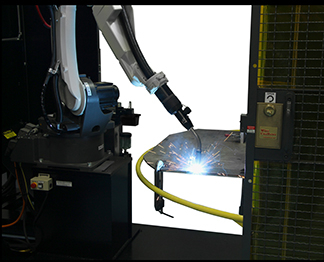
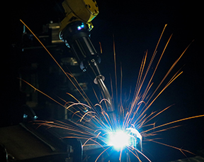
In today’s marketplace, companies continue to automate portions, if not all of their welding operation. The reasons are many: to address a shortage of skilled labour, to improve quality, to decrease waste and rework, and/or to increase productivity — in short, to seek benefits that provide a competitive edge. Not all companies, however, are successful in the process. Those beginning without a well-thought-out roadmap risk losing valuable time during implementation and operation and may miss the full benefits provided by a robotic welding system. Conversely, companies that begin with a careful examination of their welding needs and existing processes — and develop a detailed plan with clearly established goals — are more likely to achieve success. Planning should include an accurate assessment of parts, work flow and the current facility, as well as an evaluation of the potential return on investment (ROI). Companies should not only look at current needs, but also consider future opportunities to determine the best robotic welding system to scale for potential growth or changes to products they may produce later. In an economy where orders are increasing and welding positions are hard to fill, robotic welding can help maintain or increase productivity. In a semi-automatic welding operation, labour accounts for approximately 70 to 85% of the total cost of welding a part. A robotic welding system can reduce that cost and increase throughput by completing the work of two to four people in the same amount of time — however, companies still require skilled welding operators to oversee the robotic cell. 1. With the right robotic welding system, companies can improve first-pass weld quality and reduce the amount of rework or scrap parts. Depending on the welding wire and mode used, the system may also minimize or eliminate spatter, which reduces the need to apply anti-spatter compound or perform post-weld clean up. 2. A robotic welding system can reduce over-welding, a common and costly occurrence associated with the semi-automatic process. For example, if a company has welding operators who weld a bead that is 1/8-inch too large on every pass, it can potentially double the cost of welding (both for labour and for filler metals). Over-welding may also adversely affect the integrity of the part. 3. Companies can reallocate skilled employees to other production areas to fill open positions and gain additional productivity and efficiencies. 4. Welding automation can also provide a competitive advantage as it may be considered attractive to customers. The improvement in quality may prompt new customers to place orders or lead existing customers to increase their orders with the objective of growing their own businesses. 5. Finally, robots are fast. They don’t have to weld all day to be profitable. That fact improves productivity and the bottom line by making the same number of parts as in a semi-automatic process in less time. When considering an investment in a robotic welding cell, companies should have part blueprints, preferably in an electronic format. Without a blueprint, the part likely won’t meet the basic criterion necessary to ensure repeatability during the manufacturing process. A robotic welding system welds in the same place every time. When a part’s tolerances are unable to hold its position — if there are gap and/or fit-up issues — the company will simply be automating a broken process. This can increase rework or scrap. If a company currently relies on its welding operators to compensate for fit-up issues, it will need to look upstream in the manufacturing process to establish consistency. What processes need to change so these welding operators send uniform parts downstream? Or, if vendors supply the parts, can they guarantee consistency? A streamlined workflow is one of robotic welding’s benefits. To achieve it, companies need to look beyond the weld cell, making certain the facility can accommodate a smooth flow of materials. It makes little sense, for example, to invest in a robotic welding system to increase productivity, but then place it in a corner where employees may have to handle each part multiple times. There should be a consistent supply of parts to avoid moving a bottleneck from one area to another. It is also important to look at the expected cycle time of the robot. Can personnel supply parts to keep up with the demand of the robot’s cycle time? If not, the supply of parts, including where the company stores them and how it moves them, will need to be adjusted. Otherwise, a robot will sit idle waiting for components to come down the line. There is no single welding automation solution that is best for every company. When a company is considering the investment, it should factor in the expected lifetime of the job, the cost of tooling and the flexibility the equipment offers. Fixed automation is the most efficient and cost-effective way to weld parts with simple, repetitive, straight welds or round welds, where the part is rotated with a positioner. If a company wants to reuse the equipment when the current job ends, however, a robotic welding system offers more flexibility. A single robot can store programs for multiple jobs, so it may be able to handle the tasks of several fixed-automation systems. There is a certain volume of parts that justify the investment of welding automation for each company. An accurate assessment of goals and workflow can help determine what that volume is. If a company makes only small runs of parts, robotic welding becomes more challenging. But, if a company can identify two or three components that can be automated, a robot can be programmed to manufacture those parts, offering greater versatility and boosting productivity. This may benefit even small companies that may not have significant volume of a single part. Although a robot is more expensive than a fixed-automation system, it is important to consider the cost of the tooling before deciding between the two. Fixed automation systems can become quite expensive if they require extensive changes to retool a new part so it can be welded consistently. The physical footprint for a robotic welding system and the area needed for parts to flow into the welding cell is typically greater than that of a semi-automatic welding operation. The available space needs to be adequate for the robot, welding power source and other equipment. This helps minimize the need to customize products, such as cables, nozzle cleaning stations (or reamers) or the robotic MIG gun to fit the work envelope. A company with less space can still make welding automation work. One option is to purchase fewer pieces of robotic welding equipment that are capable of performing multiple tasks, such as material handling or vision/scanning systems. A third-party integrator can help determine whether a facility suits the installation of a robotic welding system. System integrators are knowledgeable about facility modifications, including important safety regulations that apply in a company’s region, country or state — in addition to those specified by OSHA and RIA (Robotic Industries Association). In addition to offering advice on facility modifications and helping a company select the right robot, a robotic systems integrator or welding automation specialist can: 1. Help determine if parts are suitable for automation, and, if not, what is required to make them suitable 2. Analyze the workflow and facility to identify potential roadblocks 3. Analyze the true costs involved with the investment, including facility updates and tooling 4. Determine the potential payback of the investment 5. Help identify goals and develop a precise plan and timetable to achieve those goals 6. Explain automation options and help select those that best fit the company’s needs 7. Help select a welding equipment that has the flexibility to maximize travel speed, minimize spatter, eliminate over-welding, provide great arc stability and increase first-pass weld quality Integrators can also help select additional equipment for the robotic welding cell, including positioners, tooling, the robotic MIG gun, welding wire and peripherals. Each item serves a distinct function. The positioner turns, rotates or otherwise moves the part into an optimal position for welding. In many cases, this involves moving the part so that the system can weld in a flat position for optimal deposition efficiency. A positioner can also allow for coordinated motion between the robot and weldment. The tooling holds the part in place during welding and is a critical component of a robotic welding system. The robot arm and robotic MIG gun travel a programmed path each cycle. If the weld joint is out of place because the part is misaligned, it can result in inadequate fusion or penetration and rework or scrap. It is important to design the tooling correctly upfront when investing in a robotic welding cell and monitor it for mechanical wear or heat distortion once it has been put into operation. This helps ensure consistent part fit up so that weld quality doesn’t suffer. The robotic MIG gun should never be an afterthought when considering an investment in welding automation, nor should the welding wire. Both can have a significant impact on productivity and profitability. An integrator can help with the selection based on how the gun and wire perform in conjunction with the rest of the system’s components. The gun will be subject to intense heat and spatter, so it must be durable. It also needs to be the appropriate size to maneuver around the tooling and gain proper joint access. Finally, peripherals, such as reamers, an anti-spatter sprayer and wire cutter are good options to discuss with an integrator prior to making the investment in welding automation. These devices can improve uptime and welding performance by keeping the welding gun consumables free of spatter, operators out of the weld cell and providing consistent wire stickout during welding. Companies cannot simply purchase a robotic welding system and let it go. They need a welding operator or other employee skilled in robotic welding programming. This will likely involve additional training to upgrade his or her skill sets. The good news is, programming a robot today is much quicker than in the past. Simplified teach pendants, along with the availability of desktop programming, help expedite the process and reduce downtime. Despite the ease of programming, however, companies may need to alleviate some existing tasks to allow time for the employee to oversee the robotic welding cell without becoming overloaded with too many responsibilities. Most robot OEMs offer a weeklong training course explaining how to operate the equipment. This course, followed by a week of advanced programming, is recommended when implementing welding automation. If the personnel investigating the prospect of robotic welding determine it’s a good fit, they will likely need to justify the investment to upper management or an owner. Calculating the potential payback is essential. There are several steps to consider. First, determine whether the volume of parts the company needs to produce requires the speed of welding automation. Remember, the key benefit of a robotic welding system is the ability to produce high volumes of quality welds or in smaller facilities to offer the flexibility to weld smaller volumes of multiple parts. Calculate payback by assessing the current volume of semi-automatic parts and cycle times. Compare these to the potential cycle times of a robotic welding system. Again, an integrator or welding automation specialist can help. Establishing the comparison is critical to estimating the potential return on investment. That said, even if a company will produce the same number of parts with a robot, it could justify the investment by the amount of labour it can reallocate elsewhere in the operation for jobs that boost production, eliminate bottlenecks or increase quality. For example, a company could utilize the skills of semi-automatic welding operators to complete challenging welds that are too complicated for a robot to manage. It’s important to factor the bulk cost of shielding gas and welding wire when looking at the potential payback. While there is an initial cost for a shielding gas/manifold system, it can help optimize a company’s robotic welding capabilities in the long term by minimizing downtime for cylinder changeover. The same is true for welding wires. The larger drums — typically ranging from 500 to 1500 pounds — can further reduce costs in a robotic welding cell since they require fewer changeovers and often come with purchasing discounts. Companies need to keep in mind that the benefits of robotic welding can be significant. However, those benefits come at an upfront price. Many companies, especially smaller ones or those that frequently change production lines, need a faster payback — no more than 12 to 15 months is common to justify the investment. If a company will have the same production needs for many years, it can typically justify a longer payback period. Management and owners should discuss their payback goals with a trusted robotic welding integrator as part of the assessment process.
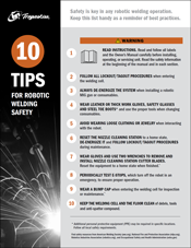
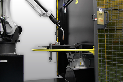
Robotic welding systems continue to gain in popularity due to their ability to increase productivity, improve quality and decrease costs in the right application. But they also offer a way to address a shortage of skilled labor for manual operations. Welding automation provide companies with a means of staying competitive in a demanding marketplace, while using their existing and potential workforce to oversee the weld cell. With more and more robotic welding systems being implemented — the Robotics Industries Association (RIA) cited that 20% of all industrial applications had robotic welding cells as of 2017 — comes the need for increased attention to safety. From the robotic welding gun and peripherals to the robot itself, following safety best practices is essential. Statistically, welding automation is safer than manual or semi-automatic welding. However, operators overseeing the robotic welding cell must still remain vigilant. This is particularly true when performing nonstandard operations; these include programming, maintenance and any other tasks that involve direct human interaction with the robot. Conducting a thorough welding risk assessment helps identify potential safety hazards associated with a specific robotic welding system (whether it is a pre-engineered or custom cell) and is a critical first step in establishing a safer welding environment. This assessment provides a baseline for implementing solutions for identified risks and establishing appropriate welding safety training. In addition, it helps companies maintain compliance with safety standards, which most importantly protects employees but also protects the bottom line. Noncompliance and/or safety violations that can lead to injury become can be costly in terms of fines and workers’ compensation. Companies can obtain welding safety resources through the American Welding Society (AWS), including Safety in Welding, Cutting, and Allied Processes, ANSI Standard Z49.1, a free download at aws.org. The National Fire and Protection Association (NFPA) also offers resources. RIA follows American National Standards Institute (ANSI) standards and offers safety seminars and webinars. RIA also provides information on industrial machinery and guarding, as well as guidelines to help companies, including the American National Standard for Industrial Robots and Robot Systems – Safety Requirements, ANSI/RIA R15.06-2012. The Occupational Safety and Health Administration (OSHA) is another valuable safety resource. Many robotic welding integrators or robotic welding system manufacturers offer training for the safe use of their equipment, including how to test safety functions and at what frequency. They also provide manuals and safety standards for their systems. It is critical to read and follow these thoroughly. Manufacturers of robotic MIG welding guns often integrate design elements into these products to aid in their safe use. These elements are intended to protect operators during routine maintenance and minimize or eliminate the need to enter the weld cell to complete tasks. For example, guns that are compatible with front-loading liners help improve safety in a robotic welding cell. These liners can be installed from outside the weld cell — there is no need to climb over tooling or maneuver around the robot to complete replacement. Operators or maintenance personnel also don’t need to remove electrical connections to replace components during the process. An insulating disc is another important safety feature in select guns. It helps protect operators from the welding current during maintenance and protects the robot from the current, limiting potential damage. In addition to integrated safety features, there are some key best practices for working with robotic welding guns, consumables and reamers (or nozzle cleaning stations). First and foremost, always de-energize the robotic welding system when installing a robotic MIG gun or consumables, and follow all lockout/tagout procedures. When possible, it’s ideal to have a window or opening that allows consumables to be changed or inspected from outside the weld cell. When possible, it’s ideal to have a window or opening that allows consumables to be changed or inspected from outside the weld cell. If this isn’t feasible, programming the robot to stop near the weld cell door simplifies consumable changeover and eliminates the need for the operator to enter the cell, maneuver around tooling or climb on anything to complete the job. The appropriate personal protective equipment (PPE) is also important when changing over consumables or the welding wire. The nozzle and contact tip may be hot, and there is the risk of the welding wire puncturing the operator. Leather or other thick work gloves are a must, and safety glasses should be worn at all times. Always use the proper tool to change over the nozzle and contact tip. A pair of welpers is recommended. When performing maintenance on a reamer, begin by resetting the equipment to a home state, de-energizing it and following lockout/tagout procedures. Be certain there is no air or electricity supplied to the reamer. When changing over cutter blades, always wear gloves and use two wrenches to remove and install them. Reset the reamer to a home state when finished. This is an important last step, as the reamer will automatically complete a cycle as soon as it receives a start signal and is reenergized. Welding operators and maintenance personnel should familiarize themselves with the emergency stops on a robotic welding system as a first safety step. The number and location of these stops varies by system. For example, welding cells typically have an operator station emergency stop that ceases all robot functions and turns off the robot servo power, along with an emergency stop on the teach pendant. Operators should test these emergency stops periodically, although testing too frequently is stressful on the mechanics of the robotic welding system. Understanding brake release procedures is also critical. RIA sets standard requirements for these; however, every robotic welding system is different, and the location of the override buttons may vary. As when interacting with a robotic MIG welding gun, consumables or reamer, always follow proper lockout/tagout procedures before entering the robotic welding cell. Many systems have multiple lockout/tagout locations that are indicated by stickers. Some pre-engineered welding cells feature sliding programming access doors with magnetic keys that indicate that they are fully open and ready to be locked out prior to maintenance, helping to prevent pinch points or a trap hazard. A built-in awareness barrier in pre-engineered cells is another means of aiding operator safety. This hooped barrier inside the weld cell covers the sweep area of the indexing table. Its purpose is to protect the operator from pinch points during teaching operations by separating the him or her from the space between the robot and the wall of the weld cell. For robotic systems that are not enclosed, guards around the cell are necessary. These can take the form of physical barriers, like perimeter fencing or light curtains and/or electronic guarding such as area scanners that stop the robot when an operator is present in a specific area of the system. Lastly, robotic integrators and robotic welding system manufacturers provide risk assessment documentation, typically in the operator’s manual. It is important to review this assessment thoroughly and train employees on the proper techniques to mitigate any identified risks. For example, programming the robot introduces mechanical hazards such as the potential for pinching or impact, which can be addressed by standing a safe distance outside of the weld cell or by using a slower teach speed if offered on the teach pendant. In addition to the best practices outlined for robotic MIG welding guns, consumables and systems, there are steps to further protect employees. Safety in welding automation should be top of mind among operators, management and maintenance personnel. Ongoing training needs to be a priority, whether it is conducted through company programs or seminars offered by outside resources. The goal is to ensure that everyone involved with the robotic welding system is playing an active role in employing best practices. When they are followed properly, the result is a safer work environment and a stronger bottom line.
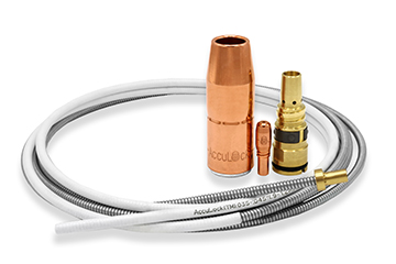
MIG welding gun configurators, like the Bernard® BTB semi-automatic air-cooled MIG gun configurator, allow you to choose specific styles or types of consumables to match the demands (amperages and waveforms) of your application. Know the wire size and type when choosing the size and style of contact tip. Joint access, operating temperatures and arc-on time are important considerations in choosing the right welding nozzle. Having the right MIG gun liner helps minimize downtime to address wire feeding issues. It is important that you always trim the liner to the proper length. Consider these tips: Note, selecting the same welding consumables across multiple weld cells, when possible, can help with inventory management and can be more cost-effective. Visit the Bernard® MIG gun configurators
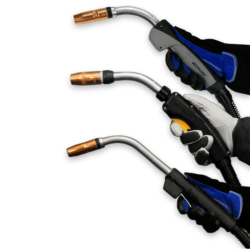
In addition to the amperage of MIG welding gun you choose, the MIG gun parts — cable, neck and handle — affect how comfortably and efficiently you can weld. Configure your gun accordingly. Cable lengths can vary greatly — from 10 feet to 25 feet or longer. Use the shortest cable possible that can get the job done to prevent kinking or creating a tripping hazard. Consider your options: Remember, smaller welding wire sizes typically call for a shorter cable; it is more difficult to push a smaller wire over a greater length. It is also more difficult to push soft wires, like aluminum, through longer cables. Choosing a neck and handle for a MIG welding gun comes down to your preference, as well as the available weld cell space and the welding wire. The bottom line: Choose the options that make it easiest and most comfortable for you to reach the weld joint. Configure a Bernard® semi-automatic MIG gun This article is the second in a three-part series discussing how configuring a MIG gun can improve the welding operation, as well as what to consider in the process. Read article one, Configuring a MIG Welding Gun for Your Application and article three, Selecting the Right MIG Welding Consumables.
Have you struggled to gain proper joint access when welding? Or found yourself fatigued at the end of the day because of repeatedly welding in awkward positions? Configuring a MIG welding gun can help. A MIG welding gun configured for the exact application can maximize efficiency and productivity. When you are more comfortable, you are able to weld longer. A customized MIG welding gun also reduces downtime for assembly, since it’s ready right out of the box. You can configure each welding gun part with online configurators like those from Bernard. These parts include the: To configure the right MIG welding gun, look at the needs of your welding application. One answer influences the next choice. The physical space of the weld cell factors into MIG welding gun configuration. Consider these factors: Taking the time to consider the factors that impact how you configure your MIG welding gun can go far in ensuring you have the exact one for your application. See options for configuring a Bernard® MIG gun This article is the first in a three-part series discussing how configuring a MIG gun can improve the welding operation, as well as what to consider in the process. Read article two, How to Choose Welding Gun Parts, and article three, Selecting the Right MIG Welding Consumables.
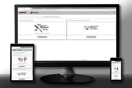
WINDSOR, Ontario (August 20, 2019) – Tregaskiss has updated the online configurators for its TOUGH GUN® CA3 robotic air-cooled MIG gun, TOUGH GUN TA3 robotic air-cooled MIG gun and the TOUGH GUN TT3 reamer robotic nozzle cleaning station with improved functionality. The new mobile-friendly configurators allow users to quickly and easily customize their robotic MIG guns and reamer for their exact application. Designed for high-volume production environments, the 385-amp TOUGH GUN CA3 robotic air-cooled MIG gun is engineered for precision, durability, accuracy and repeatability. The TOUGH GUN TA3 robotic MIG gun minimizes downtime and improves welding performance on today’s through-arm robotic welding systems, while the TOUGH GUN TT3 and TT3 (Ethernet) reamer helps extend the life of robotic MIG guns and consumables and operates reliably in even the harshest welding environments. In addition to features previously offered on the configurators, including reverse part number lookups and step-by-step product customization, the new versions provide access to expanded resources. These include a detailed summary of the configured gun or reamer, downloadable exploded view diagrams, an expanded replacement parts list with diagram, and other valuable takeaways like spec sheets and owner’s manuals. When the configurations for the TOUGH GUN CA3 and TOUGH GUN TA3 Robotic MIG Guns or TOUGH GUN TT3 Reamer are complete, the user receives a part number and parts list, and has the option to print, save in PDF format or email results. There is also the option to find contact information for a local distributor to order products from, or the user can request more information from a Customer Service representative. To access the newly updated online configurators, visit Tregaskiss.com/ConfigureMyGun. # # #
August 20, 2019 Effective immediately, a new, enhanced AccuLock™ S power pin is now available for Miller® equipment. This new power pin is designed specifically for use with the new Bernard® AccuLock S consumable system to optimize performance. Load and Lock for Better Productivity Learn more about AccuLock S consumables.
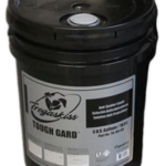
July 1, 2018 Tregaskiss has made changes to its 5-Gallon (18.9 L) TOUGH GARD® anti-spatter liquid pail design for increased strength and durability. Designed with a heavy duty integrated handle, this new container is easier to handle and can be easily stacked for maximized storage space. The new design also offers an improved seal to eliminate spillage during shipping. Like the former pail design, this new 5-Gallon container is compatible with the TOUGH GARD anti-spatter multi-feed system. Learn more about TOUGH GARD anti-spatter liquid or the TOUGH GARD anti-spatter multi-feed system.
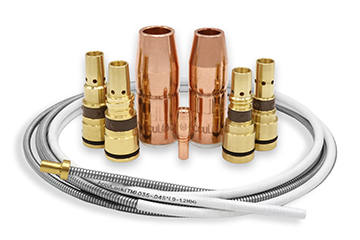
MIG welding consumables are a critical but often overlooked part of the welding operation. Unfortunately, without a clear understanding of the problems that can arise with consumables — and the best way to fix them — companies stand to lose productivity, jeopardize quality and increase costs. In some cases, the biggest issue is choosing the wrong consumable for the job. Consider this real-life example: A company with 90 arcs is using five contact tips per day, per welder — that adds up to 450 contact tips a day. By simply changing to a more robust consumable system, the company could potentially use one contact tip per welder every three to four days. The savings in reduced downtime and purchasing costs in this situation is significant. So how can companies avoid common pitfalls? A willingness to look at the impact of welding consumables on the overall operation — not just the product purchase price — is key. Training is also a vital part of success. Welding operators and maintenance personnel should know how to properly select, install and maintain consumables and troubleshoot problems when they arise. Or better yet, understand how to prevent them in the first place. Welding nozzles play an important role in the welding operation, directing shielding gas to the weld pool to protect it from contaminants. Incorrect contact tip recess within the welding nozzle is among the biggest problems. The more the contact tip is recessed, the longer the wire stickout, which can lead to an erratic arc and increased spatter in the nozzle. It can also negatively impact shielding gas coverage. In approximately 90% of applications, a 1/8-inch contact tip recess provides the best shielding gas coverage with a welding wire stickout that helps support consistent arc stability. Using the wrong welding nozzle for the application can cause downtime for changeover due to premature failure. For a standard welding application (100 to 300 amps), a copper nozzle provides good heat resistance. Copper nozzles also resist spatter buildup. For higher-amperage applications (above 300 amps), a brass welding nozzle is the better choice. Brass does not anneal as fast as copper, so the welding nozzle will maintain its hardness longer under higher temperatures. Choosing the wrong shape and size of nozzle can be problematic. Too large of a nozzle can make it difficult to obtain the joint access needed to complete a sound weld. Long or short tapered nozzles work well for restricted joints. However, there is an increased risk of spatter buildup due to the narrower bore, which can shorten the consumable’s life. To gain good gas coverage, use a longer nozzle when possible. MIG welding contact tips provide the current transfer to the welding wire to create an arc. Using a contact tip with an inside diameter (ID) that’s too small can lead to poor wire feeding and, potentially, a burnback. Using a tip with too large of an ID can cause the welding wire and arc to wander. Every consumables manufacturer has proprietary formulas for gauging contact tip ID and implementing it into their design. Select a high-quality contact tip for consistent tolerances, and match the contact tip ID to the diameter of the welding wire to gain the best electrical conductivity. This happens because the contact tip ID is actually slightly larger than the specified measurement. For example, pairing a contact tip with an ID of 0.035 inch and a wire with the same diameter allows the wire to feed smoothly through the bore, connecting enough to generate a stable welding arc. The wrong contact tip outside diameter (OD) can also cause problems. For higher amperage applications, use a contact tip with a larger OD to better withstand heat. 1. Copper contact tips provide good thermal and electrical conductivity for light- to medium-duty applications. 2. Chrome zirconium contact tips are harder than copper ones and are good for higher-amperage applications. They are also a good option if a company experiences ongoing instances of keyholing — oblong wear on the bore that can lead to an unstable arc and premature contact tip failure. 3. Contact tips are available in the marketplace that feature proprietary materials and design. These tips cost more than copper or chrome zirconium contact tips but have been shown to last more than 10 times as long. They are designed for pulsed, spray transfer or CV MIG welding. Cross-threading the contact tip is another issue that can lead to downtime. When a contact tip isn’t threaded properly during installation, or if the welding operator introduces dirt or debris to the threads, the gas diffuser can be damaged during installation. This will require replacement and increase costs. To avoid cross-threading, look for contact tips with coarse threads that install with fewer turns. The welding liner has a single and relatively simple purpose: to guide the welding wire from the wire feeder through the power cable to the contact tip. However, it is capable of causing significant problems if it isn’t installed properly. Trimming a liner incorrectly is the most common installation error. A liner that is too short lessens the support of the welding wire as it passes through the length of the gun. This can lead to micro-arcing or the formation of small arcs within the contact tip. Micro-arcing causes welding wire deposits to build up in the tip, resulting in an erratic arc and burnbacks. In more extreme cases, micro-arcing can cause MIG gun failure due to increased electrical resistance throughout the front-end consumables and gun neck. It may also prompt the welding operator to increase voltage in an effort to rectify poor welding performance, which can cause the gun to overheat. On the other hand, a too-long welding liner can lead to kinking and poor wire feeding. When trimming a conventional welding liner, avoid twisting it and use a liner gauge to ensure the proper measurement. There are also consumable systems available that provide error-proof liner installation and require no liner measuring. The gas diffuser locks the liner in place while concentrically aligning it with the power pin and contact tip to eliminate any gaps. The welding operator or maintenance personnel feeds the liner through the neck of the gun, locks it in place and cuts the liner flush with the back of the power pin. As with contact tips, remember that quality matters when it comes to welding liners. Always select a stiffer liner, so it is capable of supporting the wire as it feeds from the spool through the power pin and the length of the gun. Paying close attention to MIG gun consumables is important to gaining good welding performance. That means looking at the overall quality of the products being purchased; the manner in which they are inventoried, stored and handled; and how they are being installed. Always follows the consumable manufacturer’s recommendations, and when in doubt, contact their customer service or a trusted welding distributor for help.
Using the wrong shielding gas for MIG welding applications — or having improper gas flow — can significantly impact weld quality, costs and productivity. Shielding gas protects the molten weld pool from outside contamination, so it’s critical to choose the right gas for the job. Learn more about which gases and gas mixes are best suited for certain materials, along with some tips for optimizing gas performance — and saving money — in your welding operation.
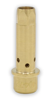
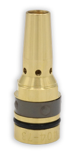
August 8, 2019 Tregaskiss is proud to announce that we have launched the following new conversion diffusers that receive TOUGH LOCK® contact tips, including HDP: Fronius® TPS 400i Lincoln® Magnum Pro® (Slip-On) Lincoln Magnum Pro (Thread-On) Learn more about TOUGH LOCK consumables.
August 1, 2019 To continue delivering sustainable value to our customers, we regularly assess our product offering to ensure focus and opportunities to innovate our product portfolio. Accordingly, due to low demand, we are discontinuing the 500 amp B Series Handle option from our BTB MIG gun offering. Effective August 16, 2019, the following part numbers will no longer be available: Please note that a comparable replacement is the O Series Handle option, which is also configurable in our BTB MIG gun product line. Learn more about Bernard® BTB MIG guns and available options, or configure a BTB MIG gun.
BEECHER, Ill./WINDSOR Ontario. (July 18, 2019) – Bernard and Tregaskiss will attend FABTECH 2019 in Chicago at McCormick Place, November 11 to 14. The companies will be in booth B23054. In addition to showcasing AccuLock™ consumables for semi-automatic and robotic welding applications, the companies will also participate in live welding demonstrations. As part of those demonstrations, the Bernard® AccuLock S consumables will be paired with Bernard semi-automatic MIG guns, power sources from Miller Electric Mfg. LLC and filler metals from Hobart in a shared area with these brands. Both Bernard and Tregaskiss will have representatives available to answer questions about semi-automatic and robotic MIG gun and consumable solutions and provide information on the companies’ technical and product support. # # #
July 30, 2019 Tregaskiss has made the following changes to its TOUGH GUN® reamer cutter blades: The above changes will be implemented as a running change and will be sold under the same part numbers as the previous design.
Robotic MIG welding guns and consumables are an important part of the welding operation yet are frequently overlooked when investing in robotic welding systems. Companies may often choose the least expensive option when, in reality, purchasing quality robotic MIG guns and consumables can lead to significant cost savings in the long run. There are many other common misconceptions about robotic MIG guns and consumables that, if corrected, can help increase productivity and decrease downtime for the entire welding operation. Here are five common misconceptions about MIG guns and consumables that may be affecting your robotic weld cell.
DISCONTINUED PRODUCT – Tregaskiss by DINSE Robotic Water-Cooled MIG Guns
DISCONTINUED PRODUCTS –
Tregaskiss by DINSE Robotic Water-Cooled MIG GunsReplacement MIG Gun Options
Parts and Consumables
NEW PRODUCT – Tregaskiss Nozzles for AccuLock R Consumables
NEW PRODUCT —
Tregaskiss Nozzles for AccuLock R ConsumablesPart Numbers
Bernard Expands AccuLock S Consumables Offering
Bernard Expands AccuLock S Consumables System
PACKAGING CHANGE – Changes to Tregaskiss and Bernard Nozzle Bag Packaging
PACKAGING CHANGE –
Changes to Tregaskiss and Bernard Nozzle Bag Packaging
Current Bag Sizes and Styles:
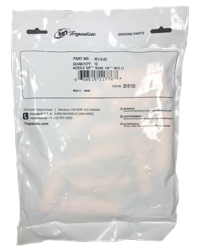
New Bag Size and Style:
Transition Timeline
AccuLock R Consumables Reduce Downtime in Robotic Welding
AccuLock R Consumables Reduce Downtime in Robotic Welding
Consumable challenges
A new consumables solution

Making the change
PRODUCT UPDATE – Firmware and Software Update for the TOUGH GUN TT3E Reamer
PRODUCT UPDATE —
Firmware and Software Update for the TOUGH GUN TT3E ReamerWhat’s New?
Compatibility
Downloads
AccuLock R Consumables Increase Throughput and Efficiency
AccuLock R Series Consumables Increase Throughput and Efficiency
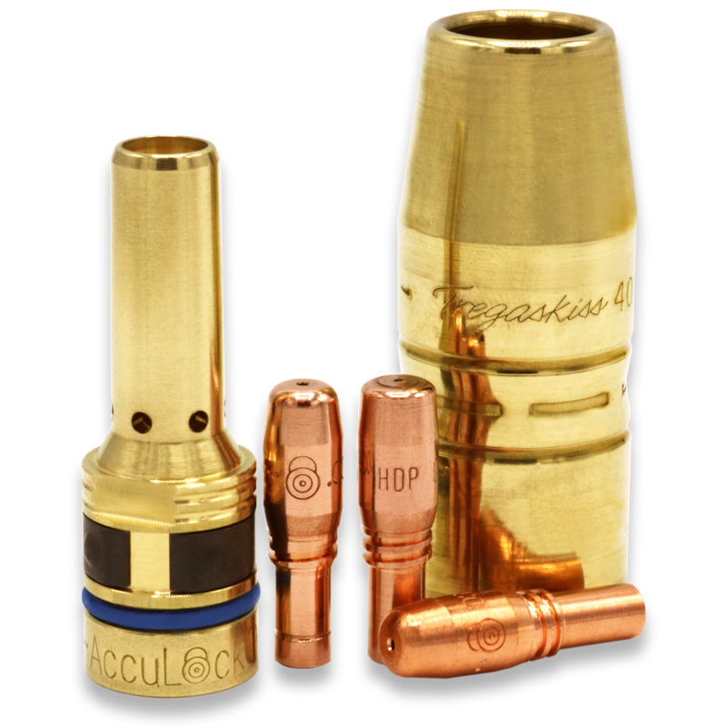
AccuLock R consumables feature an enhanced contact tip-to-diffuser design. The contact tip features increased mass at the front and 60% of the tip is buried in the diffuser, protected from the heat of the welding arc, reducing the need for frequent replacements. Tapered mating surfaces ensure optimal electrical conductivity, while also keeping the consumables locked in place.NEW PRODUCT – AccuLock R Consumables
NEW PRODUCT – AccuLock R Consumables

Series Components:
How to Successfully Implement a Robotic Welding System
How to Successfully Implement a Robotic Welding System
Why robotic welding?
In addition, the national and international marketplace has become increasingly competitive, with companies seeking contracts from any number and any size of business. Investing in welding automation can help set up a company on the path to compete at a global level.Here are additional benefits:
Repeatability is key
Assess the workflow
Robotics or fixed automation?
Consider the available space
Integrators and equipment selection
Employee training
Justifying the expense and calculating payback
Improving Welding Automation Safety With Risk Assessment and Training
Improving Welding Automation Safety With Risk Assessment and Training
Robotic welding safety hazards and resources
Safe use of robotic welding guns, consumables and reamers

Navigating the robotic welding cell safely
Other safety considerations
Creating a culture of safety
Selecting the Right MIG Welding Consumables
Selecting the Right MIG Welding Consumables
Selecting contact tips
Welding nozzle options
MIG gun liner selection
This article is the third in a three-part series discussing how configuring a MIG gun can improve the welding operation, as well as what to consider in the process. Read article one, Configuring a MIG Welding Gun for Your Application and article two, How to Choose MIG Welding Gun Parts.How to Choose MIG Welding Gun Parts
How to Choose MIG Welding Gun Parts
Choosing the cable
MIG welding gun necks and handles
Configuring a MIG Welding Gun for Your Application
Configuring a MIG Welding Gun for Your Application
Why configure?
How do you get started?
What affect does the weld cell have?
Tregaskiss Updates Robotic MIG Gun and Reamer Configurators
Tregaskiss Updates Robotic MIG Gun and Reamer Configurators
PRODUCT CHANGE – AccuLock S Power Pins for Miller Equipment
PRODUCT CHANGE –
New AccuLock S Power Pins for Miller Equipment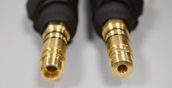
If your power pin has a large ID, please contact Customer Service to get the new AccuLock S Power Pin.
NEW (Shown Right) AccuLock S Power Pin Design
Torque to 10 ft-lbs / 120 in-lbs (13.5 Nm)Affected Part Numbers
2200137 Has been replaced by 2200206 and 2200207 in the AccuLock S consumables system as noted directly following 2200206 Replaces 2200137 for wire sizes 0.023″ (0.6 mm) – 5/64″ (2.0 mm) 2200207 Replaces 2200137 for wire sizes 3/32″ (2.4 mm) – 1/8″ (3.2 mm)
AccuLock S Consumables
PACKAGING CHANGE – 5-Gallon TOUGH GARD Anti-Spatter Liquid Pail
PACKAGING CHANGES –
5-Gallon TOUGH GARD Anti-Spatter Liquid PailAffected Part Numbers:
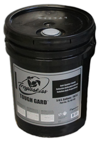
5-Gallon (18.9 L)
TOUGH GARD Anti-Spatter Liquid
Container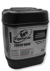
5-Gallon (18.9 L)
TOUGH GARD Anti-Spatter Liquid
ContainerCommon Problems With MIG Welding Consumables and How to Fix Them
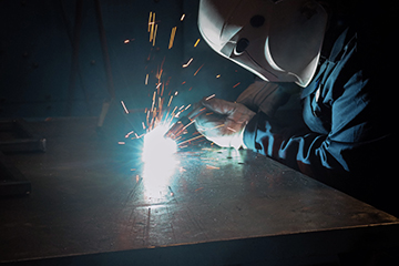
Making sense of welding nozzles
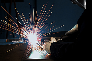
Avoiding contact tip downfalls
Pay close attention to the contact tip material to avoid premature failure. Consider these options:
Getting it straight about liners
Final considerations
Optimizing Shielding Gas Performance in MIG Welding
Optimizing Shielding Gas Performance in MIG Welding
This article was published in The WELDER. To read the entire story, please click here.
NEW PRODUCT – Conversion Diffusers for TOUGH LOCK Contact Tips
NEW PRODUCT —
Conversion Diffusers for TOUGH LOCK Contact TipsConversion Diffuser
Description
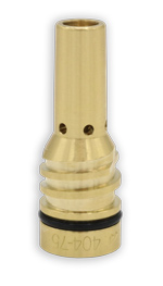
DISCONTINUED PRODUCT – BTB MIG Gun 500 amp B Series Handle Option
DISCONTINUED PRODUCT –
BTB MIG Gun 500 amp B Series Handle OptionBernard and Tregaskiss to Showcase Consumable and Gun Solutions at FABTECH 2019
Bernard and Tregaskiss to Showcase Consumable and Gun Solutions at FABTECH 2019
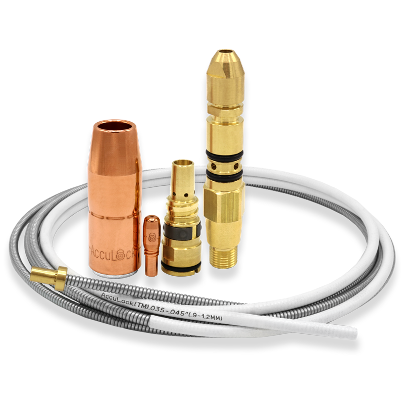
PRODUCT CHANGE – TOUGH GUN Reamer Cutter Blades
PRODUCT UPDATE —
TOUGH GUN Reamer Cutter BladesSummary of Color Changes and Affected Part Numbers
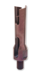
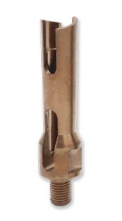
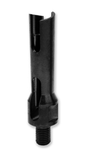
Affected Part Numbers – New Black Oxide Coating
Summary of Design Changes and Affected Part Numbers
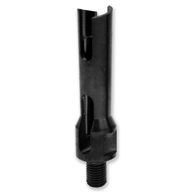
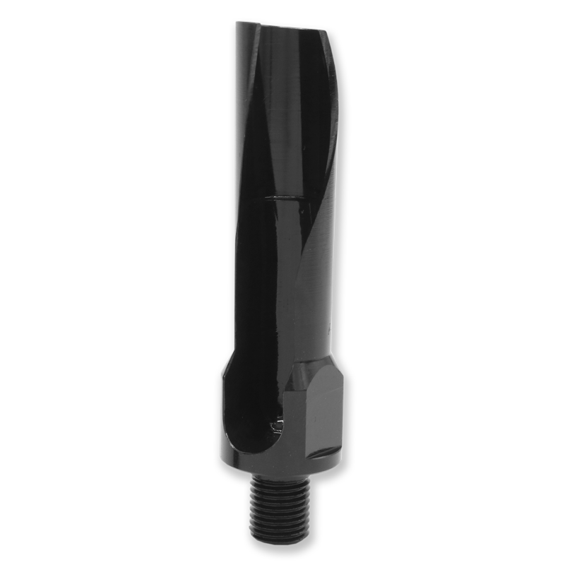
Affected Part Numbers – New Single Flute Design (effective August 1, 2019)
5 Misconceptions About Robotic Welding Guns and Consumables
5 Misconceptions About Robotic Welding Guns and Consumables

This article has been published as a web-exclusive on thefabricator.com. To read the entire story, please click here.


