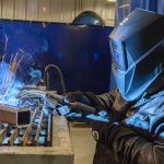
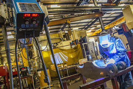
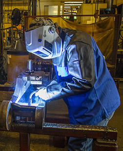
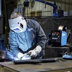
Maintaining quality, productivity and cost savings is important in any semi-automatic MIG welding operation, but the steps companies take to achieve those goals vary. Still, there is one constant: the value of skilled welders. They are at the heart of the operation and help ensure its success.
Having the right equipment and understanding how to care for it are also important, as is
revisiting the welding process regularly to ensure its efficiency. Companies should take care to watch for common pitfalls that could negatively affect their progress toward streamlining and improving their operation.
Consider these tips to help along the way:
Welder training
With the industry facing an anticipated welder shortage of 400,000 by 2024, providing training to new welders is critical to supporting a productive and profitable MIG welding operation. In many cases, employees being hired are entirely new to welding or only have limited experience. Learning best practices early on is necessary to achieve the best performance and avoid excessive downtime for troubleshooting.
Gaining good weld quality depends on welders knowing proper techniques like gun angle and gun travel speeds and the impact of welding parameters on the process. Even if a company sets lockouts that keep welding parameters within a specific range, it’s valuable for welders to understand the impact voltage, amperage, wire feed speed and shielding gas have on the application.
It’s also important to provide training on other best practices in the MIG welding operation, such as:
- Consulting a checklist for maintenance or equipment checks at the beginning and end of each shift. This can include items like securing weld grounding and checking for gun or cable damage.
- Understanding proper ergonomics to prevent repetitive stress injuries. Having welder input on gun handle types can help with this, too.
- How to correctly install consumables and at what frequency, along with how to identify the signs of contact tip wear.
- Keeping the gun uncoiled and untwisted while using it to help avoid liner movement, which typically leads to wire feeding problems.
- As part of training, encourage welders to be open to asking questions and offer refresher courses to keep skills in top shape.
MIG welding operation, it’s a good
idea to regularly assess each aspect of it.
Assessing the process
To support the long-term efficiency of a MIG welding operation, it’s a good idea to regularly assess each aspect of it.
Time studies, for example, offer excellent insight into the entire workflow and allow companies to record the amount of time each task takes to complete. These studies include a breakdown and analysis of parts handling, welding and more. By recording every activity in the operation, it is possible to see whether each one is adding value. If not, adjustments and re-sequencing can be made.
Analyzing the operation can also help identify the need for more welder training. For instance, if a significant amount of time is spent grinding after welding, it can indicate that there are issues contributing to overwelding or poor weld quality. The company can then take proactive steps for additional welder training to improve quality and reduce or eliminate the need for grinding and rework.
Similarly, if welders are spending more time transferring parts than they are welding or there are bottlenecks of parts entering the welding cell, that indicates the workflow needs to be adjusted. The goal is to minimize the amount of time welders spend handling or double handling parts and helps avoid parts from backing up or having welders sit idle waiting for them.
Improving the organization of the workstation as part of a general assessment can also help improve welding productivity. This could include adjusting welding tables and part racks to be more ergonomic so welders are more comfortable and can weld longer.
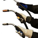
Welding gun selection and use
Having the correct MIG welding gun for the application can help enhance performance in a MIG welding operation.
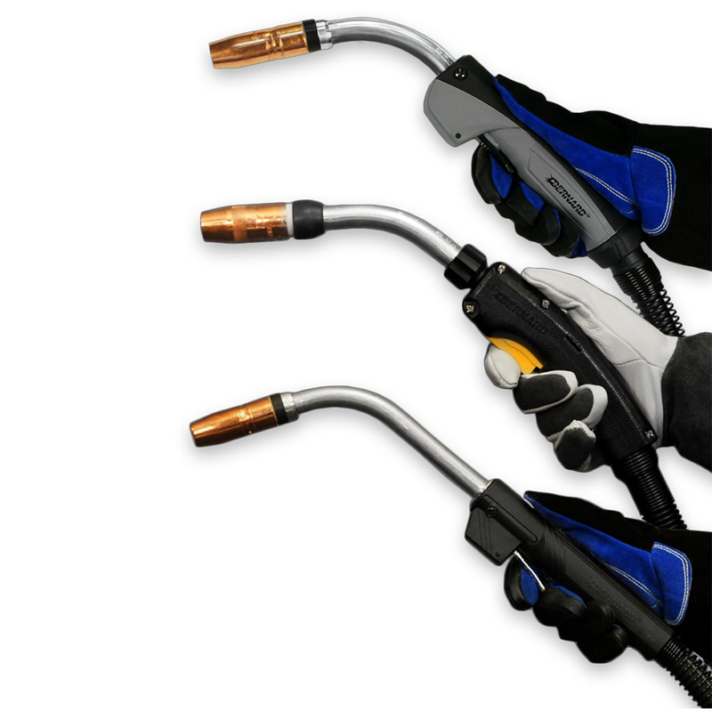
One of the first things to consider is cost. Quality MIG welding guns carry a higher price, but they are worth it in the long term. A better gun (when used properly) lasts longer and can help improve weld quality and efficiency over time. Guns that feature mechanical compression fittings, as opposed to crimped fittings, are a good choice. They typically last longer from wear and tear and can also be repaired if damaged, which saves money on replacement guns.
Be certain to choose a gun with the appropriate amperage rating and duty cycle for the application to prevent overheating. A lower amperage MIG welding gun may be appealing to a welder due to its lighter weight and flexibility; however, it will not be able to withstand an application requiring higher amperages and long arc-on times.
Effectively grounding the weld circuit is another way to gain weld quality and productivity in a semi-automatic welding operation. It can also protect the welding gun from overheating and from wearing out consumables too quickly. Installing the ground clamp as close to the weld as possible and limiting the amount of connections can help to prevent one or more from coming loose over time or creating electrical resistance.
Always choose correctly sized ground cables for the weld circuit and the right type of ground clamp. A C-clamp is a good option as it is a tighter connection versus a spring clamp, which helps prevent arcing at the ground that could lead to an erratic arc. As with other quality components in a MIG welding operation, C-clamps can be more expensive, but they offer a connection that can better protect the gun and save on replacement or repair costs.
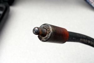
Lastly, take care to inspect the welding gun cable regularly for damage and replace as necessary. Nicks or cuts in the cable can expose bare copper, causing a safety hazard of electrical shock, as well as erratic welding issues. Adding a cable jacket cover is a proactive step in avoiding these problems.
The role of consumables and wire
Contact tips, nozzles, gas diffusers and liners all affect MIG welding performance. Ideally, select consumables and wire designed to complement one another as a system. These can help maintain solid connections that provide the best electrical conductivity and arc stability.
Always trim the liner properly — per the guns owner’s manual — to avoid erratic arcs and burn backs or look for liners that lock into place and require no measurement to avoid trimming them too long or too short.
For semi-automatic MIG welding, copper contact tips work well; however, if more tip life is desired or needed, chrome zirconium tips are an alternative to better resist physical tip wear (also known as keyholing). It helps to monitor how often contact tips are being changed to avoid straying too far from the originally planned frequency of tip changeover. If tip changes begin to increase drastically, then this points to incorrect installation of consumables, a liner being cut too short or other damage in the system. Monitoring consumables usage can also help identify when contact tips could still have life left in them. If contact tips are changed too early, this results in unnecessary downtime.
Also consider the wire being used. Quality is key here, too. Less expensive wires often have an irregular cast or helix or an inconsistent layer of lubricant. All of these factors can lead to weld quality issues and additional wear on the contact tips.
Keeping on track
Maintaining an efficient MIG welding operation takes time and resources, but it’s worthwhile to make an investment in welders and equipment to achieve the best results. Continue to monitor the process for improvement opportunities and engage welders whenever possible. Since welders are responsible for moving quality and productivity forward, their ideas can be a valuable asset.
How to Prevent Common Causes of Poor Welding Wire Feeding
How to Prevent Common Causes of Poor Welding Wire Feeding
Poor wire feeding is a common problem encountered in many welding operations. Unfortunately, it can be a significant source of downtime and lost productivity — not to mention cost.
Poor or erratic wire feeding can lead to premature failure of consumables, burnbacks, bird-nesting and more. To simplify troubleshooting, it’s best to look for issues in the wire feeder first and move toward the front of the gun to the consumables.
Finding the cause of the problem can sometimes be complicated, however, wire feeding issues often have simple solutions.
What’s happening with the feeder?
When poor wire feeding occurs, it can be related to several components in the wire feeder.
1. If the drive rolls don’t move when you pull the trigger, check to see if the relay is broken. Contact your feeder manufacturer for assistance if you suspect this is the issue. A faulty control lead is another possible cause. You can test the control lead with a multimeter to determine if a new cable is needed.
2. An incorrectly installed guide tube and/or the wrong wire guide diameter may be the culprit. The guide tube sits between the power pin and the drive rolls to keep the wire feeding smoothly from the drive rolls into the gun. Always use the proper size guide tube, adjust the guides as close to the drive rolls as possible and eliminate any gaps in the wire path.
3. Look for poor connections if your MIG gun has an adapter that connects the gun to the feeder. Check the adapter with a multimeter and replace it if it’s malfunctioning.
Take a look at the drive rolls
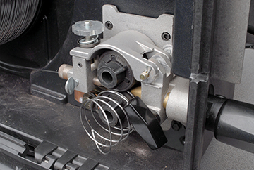
is the wrong size for the wire being used.
Using the wrong size or style of welding drive rolls can cause poor wire feeding. Here are some tips to avoid problems.
1. Always match the drive roll size to the wire diameter.
2. Inspect drive rolls every time you put a new spool of wire on the wire feeder. Replace as necessary.
3. Choose the style of drive roll based on the wire you are using. For example, smooth welding drive rolls are good for welding with solid wire, whereas U-shaped ones are better for tubular wires — flux-cored or metal-cored.
4. Set the proper drive roll tension so there is sufficient pressure on the welding wire to feed it through smoothly.
Check the liner
Several issues with the welding liner can lead to erratic wire feeding, as well as burnbacks and bird-nesting.
1. Be sure the liner is trimmed to the correct length. When you install and trim the liner, lay the gun flat, making certain the cable is straight. Using a liner gauge is helpful. There are also consumable systems available with liners that don’t require measuring. They lock and concentrically align between the contact tip and power pin without fasteners. These systems provide error-proof liner replacement to eliminate wire feeding problems.
2. Using the wrong size welding liner for the welding wire often leads to wire feeding problems. Select a liner that is slightly larger than the diameter of the wire, as it allows the wire to feed smoothly. If the liner is too narrow, it will be difficult to feed, resulting in wire breakage or bird-nesting.
3. Debris buildup in the liner can impede wire feeding. It can result from using the wrong welding drive roll type, leading to wire shavings in the liner. Microarcing can also create small weld deposits inside the liner. Replace the welding liner when buildup results in erratic wire feeding. You can also blow compressed air through the cable to remove dirt and debris when you change over the liner.
Monitor for contact tip wear
Welding consumables are a small part of the MIG gun, but they can affect wire feeding — particularly the contact tip. To avoid problems:
1. Visually inspect the contact tip for wear on a regular basis and replace as necessary. Look for signs of keyholing, which occurs when the bore in the contact tip becomes oblong over time due to the wire feeding through it. Also look for spatter buildup, as this can cause burnbacks and poor wire feeding.
2. Consider increasing or decreasing the size of contact tip you are using. Try going down one size first, which can help promote better control of the arc and better feeding.
Additional thoughts
Poor wire feeding can be a frustrating occurrence in your welding operation — but it doesn’t have to slow you down for long. If you still experience problems after inspecting and making adjustments from the feeder forward, take a look at your MIG gun. It is best to use the shortest cable possible that can still get the job done. Shorter cables minimize coiling that could lead to wire feeding issues. Remember to keep the cable as straight as possible during welding, too. Combined with some solid troubleshooting skills, the right gun can keep you welding for longer.
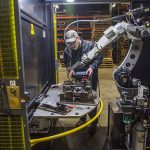
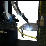
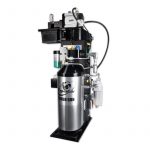
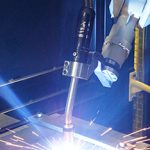
In today’s marketplace, companies continue to automate portions, if not all of their welding operation. The reasons are many: to address a shortage of skilled labour, to improve quality, to decrease waste and rework, and/or to increase productivity — in short, to seek benefits that provide a competitive edge. Not all companies, however, are successful in the process. Those beginning without a well-thought-out roadmap risk losing valuable time during implementation and operation and may miss the full benefits provided by a robotic welding system. Conversely, companies that begin with a careful examination of their welding needs and existing processes — and develop a detailed plan with clearly established goals — are more likely to achieve success. Planning should include an accurate assessment of parts, work flow and the current facility, as well as an evaluation of the potential return on investment (ROI). Companies should not only look at current needs, but also consider future opportunities to determine the best robotic welding system to scale for potential growth or changes to products they may produce later. In an economy where orders are increasing and welding positions are hard to fill, robotic welding can help maintain or increase productivity. In a semi-automatic welding operation, labour accounts for approximately 70 to 85% of the total cost of welding a part. A robotic welding system can reduce that cost and increase throughput by completing the work of two to four people in the same amount of time — however, companies still require skilled welding operators to oversee the robotic cell. 1. With the right robotic welding system, companies can improve first-pass weld quality and reduce the amount of rework or scrap parts. Depending on the welding wire and mode used, the system may also minimize or eliminate spatter, which reduces the need to apply anti-spatter compound or perform post-weld clean up. 2. A robotic welding system can reduce over-welding, a common and costly occurrence associated with the semi-automatic process. For example, if a company has welding operators who weld a bead that is 1/8-inch too large on every pass, it can potentially double the cost of welding (both for labour and for filler metals). Over-welding may also adversely affect the integrity of the part. 3. Companies can reallocate skilled employees to other production areas to fill open positions and gain additional productivity and efficiencies. 4. Welding automation can also provide a competitive advantage as it may be considered attractive to customers. The improvement in quality may prompt new customers to place orders or lead existing customers to increase their orders with the objective of growing their own businesses. 5. Finally, robots are fast. They don’t have to weld all day to be profitable. That fact improves productivity and the bottom line by making the same number of parts as in a semi-automatic process in less time. When considering an investment in a robotic welding cell, companies should have part blueprints, preferably in an electronic format. Without a blueprint, the part likely won’t meet the basic criterion necessary to ensure repeatability during the manufacturing process. A robotic welding system welds in the same place every time. When a part’s tolerances are unable to hold its position — if there are gap and/or fit-up issues — the company will simply be automating a broken process. This can increase rework or scrap. If a company currently relies on its welding operators to compensate for fit-up issues, it will need to look upstream in the manufacturing process to establish consistency. What processes need to change so these welding operators send uniform parts downstream? Or, if vendors supply the parts, can they guarantee consistency? A streamlined workflow is one of robotic welding’s benefits. To achieve it, companies need to look beyond the weld cell, making certain the facility can accommodate a smooth flow of materials. It makes little sense, for example, to invest in a robotic welding system to increase productivity, but then place it in a corner where employees may have to handle each part multiple times. There should be a consistent supply of parts to avoid moving a bottleneck from one area to another. It is also important to look at the expected cycle time of the robot. Can personnel supply parts to keep up with the demand of the robot’s cycle time? If not, the supply of parts, including where the company stores them and how it moves them, will need to be adjusted. Otherwise, a robot will sit idle waiting for components to come down the line. There is no single welding automation solution that is best for every company. When a company is considering the investment, it should factor in the expected lifetime of the job, the cost of tooling and the flexibility the equipment offers. Fixed automation is the most efficient and cost-effective way to weld parts with simple, repetitive, straight welds or round welds, where the part is rotated with a positioner. If a company wants to reuse the equipment when the current job ends, however, a robotic welding system offers more flexibility. A single robot can store programs for multiple jobs, so it may be able to handle the tasks of several fixed-automation systems. There is a certain volume of parts that justify the investment of welding automation for each company. An accurate assessment of goals and workflow can help determine what that volume is. If a company makes only small runs of parts, robotic welding becomes more challenging. But, if a company can identify two or three components that can be automated, a robot can be programmed to manufacture those parts, offering greater versatility and boosting productivity. This may benefit even small companies that may not have significant volume of a single part. Although a robot is more expensive than a fixed-automation system, it is important to consider the cost of the tooling before deciding between the two. Fixed automation systems can become quite expensive if they require extensive changes to retool a new part so it can be welded consistently. The physical footprint for a robotic welding system and the area needed for parts to flow into the welding cell is typically greater than that of a semi-automatic welding operation. The available space needs to be adequate for the robot, welding power source and other equipment. This helps minimize the need to customize products, such as cables, nozzle cleaning stations (or reamers) or the robotic MIG gun to fit the work envelope. A company with less space can still make welding automation work. One option is to purchase fewer pieces of robotic welding equipment that are capable of performing multiple tasks, such as material handling or vision/scanning systems. A third-party integrator can help determine whether a facility suits the installation of a robotic welding system. System integrators are knowledgeable about facility modifications, including important safety regulations that apply in a company’s region, country or state — in addition to those specified by OSHA and RIA (Robotic Industries Association). In addition to offering advice on facility modifications and helping a company select the right robot, a robotic systems integrator or welding automation specialist can: 1. Help determine if parts are suitable for automation, and, if not, what is required to make them suitable 2. Analyze the workflow and facility to identify potential roadblocks 3. Analyze the true costs involved with the investment, including facility updates and tooling 4. Determine the potential payback of the investment 5. Help identify goals and develop a precise plan and timetable to achieve those goals 6. Explain automation options and help select those that best fit the company’s needs 7. Help select a welding equipment that has the flexibility to maximize travel speed, minimize spatter, eliminate over-welding, provide great arc stability and increase first-pass weld quality Integrators can also help select additional equipment for the robotic welding cell, including positioners, tooling, the robotic MIG gun, welding wire and peripherals. Each item serves a distinct function. The positioner turns, rotates or otherwise moves the part into an optimal position for welding. In many cases, this involves moving the part so that the system can weld in a flat position for optimal deposition efficiency. A positioner can also allow for coordinated motion between the robot and weldment. The tooling holds the part in place during welding and is a critical component of a robotic welding system. The robot arm and robotic MIG gun travel a programmed path each cycle. If the weld joint is out of place because the part is misaligned, it can result in inadequate fusion or penetration and rework or scrap. It is important to design the tooling correctly upfront when investing in a robotic welding cell and monitor it for mechanical wear or heat distortion once it has been put into operation. This helps ensure consistent part fit up so that weld quality doesn’t suffer. The robotic MIG gun should never be an afterthought when considering an investment in welding automation, nor should the welding wire. Both can have a significant impact on productivity and profitability. An integrator can help with the selection based on how the gun and wire perform in conjunction with the rest of the system’s components. The gun will be subject to intense heat and spatter, so it must be durable. It also needs to be the appropriate size to maneuver around the tooling and gain proper joint access. Finally, peripherals, such as reamers, an anti-spatter sprayer and wire cutter are good options to discuss with an integrator prior to making the investment in welding automation. These devices can improve uptime and welding performance by keeping the welding gun consumables free of spatter, operators out of the weld cell and providing consistent wire stickout during welding. Companies cannot simply purchase a robotic welding system and let it go. They need a welding operator or other employee skilled in robotic welding programming. This will likely involve additional training to upgrade his or her skill sets. The good news is, programming a robot today is much quicker than in the past. Simplified teach pendants, along with the availability of desktop programming, help expedite the process and reduce downtime. Despite the ease of programming, however, companies may need to alleviate some existing tasks to allow time for the employee to oversee the robotic welding cell without becoming overloaded with too many responsibilities. Most robot OEMs offer a weeklong training course explaining how to operate the equipment. This course, followed by a week of advanced programming, is recommended when implementing welding automation. If the personnel investigating the prospect of robotic welding determine it’s a good fit, they will likely need to justify the investment to upper management or an owner. Calculating the potential payback is essential. There are several steps to consider. First, determine whether the volume of parts the company needs to produce requires the speed of welding automation. Remember, the key benefit of a robotic welding system is the ability to produce high volumes of quality welds or in smaller facilities to offer the flexibility to weld smaller volumes of multiple parts. Calculate payback by assessing the current volume of semi-automatic parts and cycle times. Compare these to the potential cycle times of a robotic welding system. Again, an integrator or welding automation specialist can help. Establishing the comparison is critical to estimating the potential return on investment. That said, even if a company will produce the same number of parts with a robot, it could justify the investment by the amount of labour it can reallocate elsewhere in the operation for jobs that boost production, eliminate bottlenecks or increase quality. For example, a company could utilize the skills of semi-automatic welding operators to complete challenging welds that are too complicated for a robot to manage. It’s important to factor the bulk cost of shielding gas and welding wire when looking at the potential payback. While there is an initial cost for a shielding gas/manifold system, it can help optimize a company’s robotic welding capabilities in the long term by minimizing downtime for cylinder changeover. The same is true for welding wires. The larger drums — typically ranging from 500 to 1500 pounds — can further reduce costs in a robotic welding cell since they require fewer changeovers and often come with purchasing discounts. Companies need to keep in mind that the benefits of robotic welding can be significant. However, those benefits come at an upfront price. Many companies, especially smaller ones or those that frequently change production lines, need a faster payback — no more than 12 to 15 months is common to justify the investment. If a company will have the same production needs for many years, it can typically justify a longer payback period. Management and owners should discuss their payback goals with a trusted robotic welding integrator as part of the assessment process.
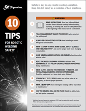
Robotic welding systems continue to gain in popularity due to their ability to increase productivity, improve quality and decrease costs in the right application. But they also offer a way to address a shortage of skilled labor for manual operations. Welding automation provide companies with a means of staying competitive in a demanding marketplace, while using their existing and potential workforce to oversee the weld cell. With more and more robotic welding systems being implemented — the Robotics Industries Association (RIA) cited that 20% of all industrial applications had robotic welding cells as of 2017 — comes the need for increased attention to safety. From the robotic welding gun and peripherals to the robot itself, following safety best practices is essential. Statistically, welding automation is safer than manual or semi-automatic welding. However, operators overseeing the robotic welding cell must still remain vigilant. This is particularly true when performing nonstandard operations; these include programming, maintenance and any other tasks that involve direct human interaction with the robot. Conducting a thorough welding risk assessment helps identify potential safety hazards associated with a specific robotic welding system (whether it is a pre-engineered or custom cell) and is a critical first step in establishing a safer welding environment. This assessment provides a baseline for implementing solutions for identified risks and establishing appropriate welding safety training. In addition, it helps companies maintain compliance with safety standards, which most importantly protects employees but also protects the bottom line. Noncompliance and/or safety violations that can lead to injury become can be costly in terms of fines and workers’ compensation. Companies can obtain welding safety resources through the American Welding Society (AWS), including Safety in Welding, Cutting, and Allied Processes, ANSI Standard Z49.1, a free download at aws.org. The National Fire and Protection Association (NFPA) also offers resources. RIA follows American National Standards Institute (ANSI) standards and offers safety seminars and webinars. RIA also provides information on industrial machinery and guarding, as well as guidelines to help companies, including the American National Standard for Industrial Robots and Robot Systems – Safety Requirements, ANSI/RIA R15.06-2012. The Occupational Safety and Health Administration (OSHA) is another valuable safety resource. Many robotic welding integrators or robotic welding system manufacturers offer training for the safe use of their equipment, including how to test safety functions and at what frequency. They also provide manuals and safety standards for their systems. It is critical to read and follow these thoroughly. Manufacturers of robotic MIG welding guns often integrate design elements into these products to aid in their safe use. These elements are intended to protect operators during routine maintenance and minimize or eliminate the need to enter the weld cell to complete tasks. For example, guns that are compatible with front-loading liners help improve safety in a robotic welding cell. These liners can be installed from outside the weld cell — there is no need to climb over tooling or maneuver around the robot to complete replacement. Operators or maintenance personnel also don’t need to remove electrical connections to replace components during the process. An insulating disc is another important safety feature in select guns. It helps protect operators from the welding current during maintenance and protects the robot from the current, limiting potential damage. In addition to integrated safety features, there are some key best practices for working with robotic welding guns, consumables and reamers (or nozzle cleaning stations). First and foremost, always de-energize the robotic welding system when installing a robotic MIG gun or consumables, and follow all lockout/tagout procedures. When possible, it’s ideal to have a window or opening that allows consumables to be changed or inspected from outside the weld cell. When possible, it’s ideal to have a window or opening that allows consumables to be changed or inspected from outside the weld cell. If this isn’t feasible, programming the robot to stop near the weld cell door simplifies consumable changeover and eliminates the need for the operator to enter the cell, maneuver around tooling or climb on anything to complete the job. The appropriate personal protective equipment (PPE) is also important when changing over consumables or the welding wire. The nozzle and contact tip may be hot, and there is the risk of the welding wire puncturing the operator. Leather or other thick work gloves are a must, and safety glasses should be worn at all times. Always use the proper tool to change over the nozzle and contact tip. A pair of welpers is recommended. When performing maintenance on a reamer, begin by resetting the equipment to a home state, de-energizing it and following lockout/tagout procedures. Be certain there is no air or electricity supplied to the reamer. When changing over cutter blades, always wear gloves and use two wrenches to remove and install them. Reset the reamer to a home state when finished. This is an important last step, as the reamer will automatically complete a cycle as soon as it receives a start signal and is reenergized. Welding operators and maintenance personnel should familiarize themselves with the emergency stops on a robotic welding system as a first safety step. The number and location of these stops varies by system. For example, welding cells typically have an operator station emergency stop that ceases all robot functions and turns off the robot servo power, along with an emergency stop on the teach pendant. Operators should test these emergency stops periodically, although testing too frequently is stressful on the mechanics of the robotic welding system. Understanding brake release procedures is also critical. RIA sets standard requirements for these; however, every robotic welding system is different, and the location of the override buttons may vary. As when interacting with a robotic MIG welding gun, consumables or reamer, always follow proper lockout/tagout procedures before entering the robotic welding cell. Many systems have multiple lockout/tagout locations that are indicated by stickers. Some pre-engineered welding cells feature sliding programming access doors with magnetic keys that indicate that they are fully open and ready to be locked out prior to maintenance, helping to prevent pinch points or a trap hazard. A built-in awareness barrier in pre-engineered cells is another means of aiding operator safety. This hooped barrier inside the weld cell covers the sweep area of the indexing table. Its purpose is to protect the operator from pinch points during teaching operations by separating the him or her from the space between the robot and the wall of the weld cell. For robotic systems that are not enclosed, guards around the cell are necessary. These can take the form of physical barriers, like perimeter fencing or light curtains and/or electronic guarding such as area scanners that stop the robot when an operator is present in a specific area of the system. Lastly, robotic integrators and robotic welding system manufacturers provide risk assessment documentation, typically in the operator’s manual. It is important to review this assessment thoroughly and train employees on the proper techniques to mitigate any identified risks. For example, programming the robot introduces mechanical hazards such as the potential for pinching or impact, which can be addressed by standing a safe distance outside of the weld cell or by using a slower teach speed if offered on the teach pendant. In addition to the best practices outlined for robotic MIG welding guns, consumables and systems, there are steps to further protect employees. Safety in welding automation should be top of mind among operators, management and maintenance personnel. Ongoing training needs to be a priority, whether it is conducted through company programs or seminars offered by outside resources. The goal is to ensure that everyone involved with the robotic welding system is playing an active role in employing best practices. When they are followed properly, the result is a safer work environment and a stronger bottom line.
Using the wrong shielding gas for MIG welding applications — or having improper gas flow — can significantly impact weld quality, costs and productivity. Shielding gas protects the molten weld pool from outside contamination, so it’s critical to choose the right gas for the job. Learn more about which gases and gas mixes are best suited for certain materials, along with some tips for optimizing gas performance — and saving money — in your welding operation.
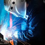
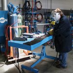
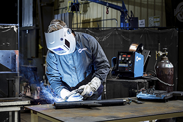
It’s important for new welding operators to establish proper MIG techniques in order to achieve good weld quality and maximize productivity. Safety best practices are key, too. It’s just as important, however, for experienced welding operators to remember the fundamentals in order to avoid picking up habits that could negatively impact welding performance. From employing safe ergonomics to using the proper MIG gun angle and welding travel speeds and more, good MIG welding techniques provide good results. Here are some tips. A comfortable welding operator is a safer one. Proper ergonomics should be among the first fundamentals to establish in the MIG welding process (along with proper personal protective equipment, of course). Ergonomics can be defined, simply, as the “study of how equipment can be arranged so that people can do work or other activities more efficiently and comfortably.”1 The importance of ergonomics for a welding operator can have far reaching effects. A workplace environment or task that causes a welding operator to repetitively reach, move, grip or twist in an unnatural way, or even stay in a static posture for an extended period of time without rest, can lead to repetitive stress injuries with life-long impacts. Proper ergonomics can protect welding operators from injury while also improving productivity and profitability of a welding operation by reducing employee absences. 1. Using a MIG welding gun with a locking trigger to prevent “trigger finger,” which is caused by applying pressure to a trigger for an extended period of time. 2. Using a MIG gun with a rotatable neck to help the welding operator move more easily to reach a joint with less strain on the body. 3. Keeping hands at elbow height or slightly below while welding. 4. Positioning work between the welding operator’s waist and shoulders to ensure welding is being completed in as close of a neutral posture as possible. 5. Reducing the stress of repetitive motions by using MIG guns with rear swivels on the power cable. 6. Using different combinations of handle angles, neck angles and neck lengths to keep the welding operator’s wrist in a neutral position. The proper welding gun or work angle, travel angle and MIG welding technique depends on the thickness of the base metal and the welding position. Work angle is “the relationship between the axis of the electrode to the welders work piece.” Travel angle refers to employing either a push angle (pointing in the direction of travel) or a drag angle, when the electrode is pointed opposite of travel. (AWS Welding HandBook 9th Edition Vol 2 Page 184)2. Flat position For T-joints, hold the gun at a work angle of 45 degrees and for lap joints a work angle around 60 degrees is appropriate (15 degrees up from 45 degrees). Horizontal position Vertical position The uphill direction is used for thicker material when greater penetration is needed. A good technique for a T-Joint is call the upside-down V. This technique assures the welding operator maintains consistency and penetration in the root of the weld, which is where the two pieces meet. This area is the most important part of the weld.The other technique is downhill welding. This is popular in the pipe industry for open root welding and when welding thin gauge materials. Overhead position Wire stickout and contact-tip-to-work distance Proper contact-tip-to-work distance (CTWD) is also important to gaining good welding performance. The CTWD used depends on the welding process. For example, when using a spray transfer mode, if the CTWD is too short, it can cause burnbacks. If it’s too long, it could cause weld discontinuities due to lack of proper shielding gas coverage. For spray transfer welding, a 3/4-inch CTWD is appropriate, while 3/8 to 1/2 inch would work for short circuit welding. Welding travel speed With a welding travel speed that’s too fast, welding operators will end up with a narrow, convex bead with inadequate tie-in at the toes of the weld. Insufficient penetration, distortion and an inconsistent weld bead are caused by traveling too fast. Traveling too slow can introduce too much heat into the weld, resulting in an excessively wide weld bead. On thinner material, it may also cause burn through. When it comes to improving safety and productivity, it’s up to the experienced veteran welding operator as much as the new welding to establish and follow proper MIG technique right. Doing so helps avoid potential injury and unnecessary downtime for reworking poor quality welds. Keep in mind that it never hurts for welding operators to refresh their knowledge about MIG welding and it’s in their and the company’s best interest to continue following best practices. 1. Collins Dictionary, “ergonomics,” collinsdictionary.com/dictionary/english/ergonomics.
The potential advantages of robotic welding are well known — increased productivity, improved quality and greater cost savings compared to semi-automatic welding. But the question is: How do companies best implement this technology to gain these benefits? And how can they ensure a quick return on the investment (ROI)? Simply stated, planning. More preparation upfront helps minimize the cost and time for correcting errors in the robotic welding system once it has gone into production. From the welding power source to the robot or weld process to the gun and consumables, each component should be thoroughly researched to make sure it is feasible to operate in the weld cell — not just on paper, but in reality. Take advantage of turnkey integrators who run their own process and capability studies. They can provide useful double checks to a plan and often conduct reach studies that model the weld tooling and workpiece. These mock up how the robot would weld in the finished system to test the gun reach and the overall efficiency of the process. Also remember, success in robotic welding is as much a matter of doing the right thing as it is avoiding pitfalls that could hinder the efficiency of the operation. With planning comes budgeting. A robotic welding cell may be installed on time, produce good weld quality and meet cycle time, but if the implementation and use of the system is over budget it will be an uphill battle to gain a good ROI. Consider the associated goals to help establish a feasible ROI. For example, a company with the goal of producing 1000 parts a day needs to determine how much it can make from those parts. From there, it would subtract the cost of utilities and labor, along with the cost to make the product and the cost of raw materials, to determine a budget on equipment costs that would make the company profitable. If this equipment will only be used for 5 years, the company may need a quicker ROI than if it’s planning to use the robotic welding system for 10 years or more. Companies can make the most of their budget by considering equipment that could be reused. This can cut down on the investment in the long run. Robots can have an extensive life if maintained well, allowing them to be re-purposed from project to project. The same holds true with welding power sources and nozzle cleaning stations. Ultimately, ROI depends on the company and what practices it follows for making profit. Some may be able to allow the equipment to take 18 months or more to pay for itself if the company plans on re-using or re-purposing the welding robots on multiple platforms over the next 10 years. Others may stand by the goal of a one-year ROI, which is common. Proper training is important for keeping a robotic welding system running successfully and profitably in the long term. Robot integrators and other equipment manufacturers often offer training as part of the implementation process. This training provides welding operators with a knowledge of robotic welding in general, as well as providing the information they need to operate the robot effectively for the application at hand. A well-trained operator will also be able to determine ways to maximize the efficiency of the robotic weld cell. They do this by troubleshooting and resolving issues quickly, keeping the robot online and supporting greater productivity and cost savings. Likewise, train welding operators to implement PM for the robotic gas metal arc welding (GMAW) gun to gain longer life, reduce downtime and achieve more arc-on time. Regularly check that the gun connections, consumables and power pin are secure. Look for any signs of power cable wear and replace if necessary.Training geared toward the preventive maintenance (PM) of a robotic welding system and the weld cell is also key. For example, spatter build-up on the robotic welding gun can cause grounding issues and build-up on tooling may lead to dimensional movement of the steel from cycle to cycle. The latter can block the datum placements causing gun reach issues. In a worse-case scenario, spatter builds up on equipment over time, creating solid formations that are difficult to remove and prevent the re-use of the equipment. To avoid these problems, train operators to follow a regular cleaning schedule for the weld cell and the equipment. There are several common mistakes that can negatively affect productivity and quality in a robotic welding system. Knowing how to avoid these can help companies make the most out of the equipment and gain greater success. Consider the following: 1. Implementing the wrong equipment in a robotic welding cell can lead to spending more money than is required. Be sure the power source, robotic GMAW gun and consumables are rated for the application. Doing so helps minimize the risk of premature equipment failures that can lead to unplanned downtime and costly equipment replacement. For example, if a company selects an air-cooled system, but actually requires a water-cooled system for the application, it could incur unnecessary costs to repair or upgrade a failed robotic GMAW gun system that cannot handle the heat. 2. Underutilizing the robotic welding system can prevent companies from realizing their full productivity potential. Robotic welding systems should be programmed to maximize the arc-on time during the weld process cycle. In some cases, it may be possible to have fewer robots that weld for slightly longer cycles. This helps drop the initial implementation costs. Take this example. A company has four robots in cell welding at 30 inches per minute with a cycle time of 60 seconds. These robots are inefficient since they are only welding half of the cycle time. That could be due to the positioner rotating for weld access, too slow of robot air cut movements, poor welding angles or other limiting factors. In this scenario, the total length of completed welds for all four robots is 60 inches (30 in. / min. x 1 min. / 60 seconds x 30 seconds of welding per robot = 15 inches of weld per robot). An alternative here is to keep the cycle time at 60 seconds and drop down to three robots by improving items like the weld angles, creating quicker air cuts between welds, utilizing gun reaming during positioner movements and more. Now with improvements, the robots could weld at an average of 35 inches per minute for 35 seconds each cycle. That provides an average of 20 inches of weld per cycle per robot, allowing for the same total of 60 inches of weld with one less robot. 3. Underutilizing available labor can also hinder productivity. While companies should take care not to overload operators, it’s important to balance manpower in robotic welding process so that employees are efficient and busy at the same time. If an operator is idle waiting for the weld cycle to complete, there could be room for process improvements by allocating labor to other activities near the weld cell. 4. Poor tooling design can impede quality. Thoroughly plan the tooling design and understand how the parts being welded will impact it. Different parts and materials react differently to heat and may draw, flex or bend during the welding process. Factor in how much heat a given weld sequence generates. The tooling will have to be designed with these in mind. If possible, design tooling to permit welding in the flat or horizontal position with appropriate robotic GMAW gun access. This allows for faster and more consistent results. Finally, remember, less expensive tooling may be attractive when looking at upfront costs, but it can be a pitfall later if it doesn’t meet the demands of the job. 5. Overlooking activities outside the robotic weld cell can be detrimental. Plan for part inspection and cosmetic rework, as well as the final stages of palletizing the product if that is part of the operation. Some of these processes can be automated or manual labor driven. These are key stages in a robotic welding operation that can quickly become bottlenecks that cause the entire process to slow down. These bottlenecks can also add unplanned manpower or equipment costs, which can become expensive. Remember that no plan for welding automation can be successful without a good schedule for its implementation. Being thorough is more important than being fast. Set realistic goals for completing the installation of the robotic weld cells and don’t rush or over-complicate the process. For first-time investors in robotic welding starting small can also help ensure greater success. Once the robotic weld cell or cells begin operating, keep in mind that the startup may not be perfect. There may be adjustments required to optimize performance to gain the best productivity and quality.
From reamers or nozzle cleaning stations to wire cutters and anti-spatter sprayers, welding peripherals and accessories can contribute significantly to the success of a robotic welding operation. In addition to improving weld quality, they can also help companies maintain high levels of productivity. Reamers, in particular, are most prevalent in automotive manufacturing, where uptime and quality are critical. This peripheral cleans the welding consumables — for example, welding nozzles and gas diffusers — free of spatter, and most automotive welding operations rely on the process after virtually every weld cycle. Other industries, such as heavy equipment manufacturing, also employ reamers and other peripherals in their robotic welding operations, as do some general manufacturers. It’s not by chance that peripherals work the way they do. Like any equipment, caring for them with routine preventive maintenance (PM) is important to gaining optimal performance and longevity. A reamer requires regular attention since it operates frequently during the weld cycles. Its job is important though, as it performs essential welding nozzle cleaning that helps keep the robotic welding cell up and running and quality on par. With the PM for this equipment also comes PM for its associated accessories: the lubricator, cutter blades and anti-spatter sprayer. All require varying levels of PM activities — some daily, weekly, monthly or yearly. In addition to inspecting the consumables for wear and replacing as needed, follow this PM routine on a daily basis: On a weekly basis, continue to examine the integrity of the consumables and follow these guidelines: Monthly PM for reamers and accessories requires less steps but is more intensive. It may require scheduling a time off cycle to complete. Lastly, on an annual basis: While it may seem time-consuming to implement these PM measures, they can typically be completed during routine pauses in production. More intensive activities can be scheduled so as to prevent interruption to production. Ultimately, the PM is time well spent and can help protect the investment in the reamer and its accessories. Wire cutters are increasingly being used in automotive and other manufacturing operations. This equipment is integrated into a reamer configuration and used in conjunction with a wire brake on the robotic MIG gun. The wire brake prevents the welding wire from moving, while the wire cutter cuts it at a set distance. This allows for a consistent wire stickout so the robot can touch sense and track the joint before welding. The results are more accurate weld placement and smooth arc starting. PM for wire cutters is relatively simple. Peripherals like reamers with anti-spatter sprayers and wire cutters can help companies realize a greater return on their investment in a robotic welding system. They aid in high weld quality, minimize rework and help meet productivity goals. Train welding operators to follow recommended PM activities as a part of a routine care of the weld cell. The time and cost to care for them properly will be small in comparison to the improvements they can provide to the bottom line.
Every operation wants to avoid downtime, as well as the cost for troubleshooting problems in the robotic welding cell. But sometimes issues happen, whether it’s due to equipment failure or human error. Since most companies invest in welding automation to boost throughput and profitability, getting a robotic welding cell back online as quickly as possible is critical to production and the bottom line. The first things to consider are whether anything has changed in the welding process or with the equipment, or if the operator has recently reprogrammed the robot. In many cases, evaluating the most recently changed variable can help you pinpoint an issue’s cause. After that, analyzing some of the most frequent sources of trouble in the robotic weld cell can help you get to the root of the problem sooner. Consider these five common issues and ways to fix them. A: The material being welded and the parameters being used affect welding consumables’ longevity. But if it seems that nozzles, contact tips, diffusers or liners aren’t lasting their typical life or are performing poorly, there could be several causes. Check all connections between welding consumables and tighten them as needed. A loose connection increases electrical resistance and generates additional heat, which can shorten consumable life and cause poor performance. It’s especially important to ensure consumables are properly tightened when the application involves long welds or welds on thick materials, since any rework due to quality issues will cost more time and money in these cases. Common contact tips issues, such as burnback, are often caused by a too-short liner. Always follow the manufacturer’s instructions for liner trimming and installation, and use a liner gauge to confirm length when possible. Over time, debris and spatter buildup inside the liner can contribute to shortened contact tip life. It’s important to create a schedule for changing liners, just as you would for other consumables. If you’re frequently experiencing weld defects like porosity or lack of penetration, this can also stem from a consumables issue. Make sure the contact tip and nozzle are free of debris and replace them as needed. A: Erratic or poor wire feeding in robotic welding is a common issue that can ultimately result in poor weld quality. Poor wire feeding can have many causes. Cutting a liner too short is particularly problematic when robotic welding with smaller diameter wires, which have less column strength. Extreme articulation of the robotic MIG gun can also lead to poor wire feeding. Program the robotic MIG gun cable to stay as straight as possible. The robot may not weld quite as fast, but proper gun orientation helps minimize downtime for feeding problems. Excessive conduit length and multiple bends or junctions can cause poor wire feeding as well. With the drive rolls open, you should be able to pull the wire through the contact tip by hand with minimal effort. If you need to pull with two hands or put your bodyweight into the process, that indicates interference with the wire path between the wire drum and the contact tip. Check for bends tighter than 90 degrees, multiple junctions between sections of conduit or worn conduit sections that can increase drag on the wire. Ideally, the conduit between the drum and the wire feeder should be less than 20 feet, with no junctions or tight bends. Improper drive roll selection and tension setting can also lead to poor wire feeding. Consider the size and type of wire being used and match that to the drive rolls. Inspect drive rolls for signs of wear and replace them as necessary. A: Whether you have a through-arm robotic welding system, where the cable is routed through the robotic arm, or a standard over-the-arm robotic welding system, premature power cable failure can happen. A power cable that becomes kinked or worn can fail and short-out against the robot casting, leading to costly repairs. To help prevent premature cable wear, consider the programmed path of the robot as well as the power cable’s length. If the robot’s movements cause the cable to bunch up or kink, it can cause the power cable to fail. If the power cable rubs against tooling or catches on components during the programmed cycle, this can also cause premature failure. A: In robotic welding, TCP refers to the location of the end of the welding wire with respect to the end of the robot arm. If you are experiencing inconsistent welds or welds that are off-location, this may stem from a problem with TCP. If the robotic MIG gun neck is bent or damaged during a collision in the weld cell, this can result in TCP issues. Use a neck-checking fixture or neck alignment tool to help ensure proper angle of the neck bend. Also, be sure the neck and consumables are installed and torqued properly. Failure to do so may affect TCP. However, a problem with off-location welds isn’t always caused by TCP issues. Improper fixturing or part variations may also be the root cause. If a TCP check using the robotic program turns up with no issues, a part or position variation is the likely culprit. A: Companies often implement peripherals, such as reamers or nozzle cleaning stations, to optimize robotic welding performance and get more life out of consumables. But a problem with the reamer can cause spatter buildup on the consumables. Reamers can perform poorly for three common reasons: Problems in the robotic welding cell can be as simple as a loose contact tip or more complex like incorrect TCP. Understanding the steps for proper troubleshooting helps narrow down potential causes and can prevent replacement of components that don’t need replacing — so the operation can save money and quickly get back to producing quality parts. Learn more from the Tregaskiss Troubleshooting Guide.
Implementing robotic welding can significantly improve a manufacturing operation’s productivity and weld quality, but what are the robotic welding basics you should know to be successful? From choosing the right welding wire to establishing proper tool center point (TCP), many variables play a role in optimizing robotic welding cells to produce the best results. Shaving even a few seconds from each weld cycle can save time and money. Minimizing the unplanned downtime for adjustments or repairs in the weld cell can also have a substantial impact on your bottom line. Success with robotic welding requires a well-researched plan. The more planning done upfront, the less time and money you could spend later making fixes and process improvements. Learning some basic tips for setting up a robotic weld cell can help to establish a repeatable and consistent process — so your operation can produce quality welds, reduce rework and maximize its investment. Proper weld settings for the application are based on factors including wire size and material thickness. Some welding power sources offer technology that allows welders to simply input the wire size and material thickness, and the machine will suggest recommended parameters for the application. Without this technology, finding the correct parameters can involve a bit of trial and error. Sometimes the robot manufacturer, welding power source manufacturer or system integrator can assist in choosing and testing specific materials to provide a starting point for the proper welding parameters. Utilize the experience of these partners to help you arrive at the best starting point and be prepared for the future. The choice of filler metal for a robotic welding system can significantly impact productivity, weld quality and the overall investment. Selecting the right wire for a robotic application is typically based on the material type and thickness, as well as the expected outcomes for the welded part. Welding equipment and filler metal manufacturers often offer charts to help you match a welding wire to your process needs. While solid wire has been the industry standard in robotic welding for many years, metal-cored wire is an alternative that can offer productivity and quality improvements in some applications, particularly in the manufacture of heavy equipment and automotive exhaust, chassis and wheels. However, be aware that each wire type offers pros and cons for certain applications, so it’s important to research the type that is best suited to your application. Robotic welding guns and consumables, including the nozzle, contact tip and gas diffuser, have a huge impact on performance in a robotic weld cell. The right combination can reduce unplanned downtime and improve overall efficiency of the cell. Be sure the welding gun is rated with enough duty cycle and amperage for the application. To avoid excessive wear and premature failure, the gun should not rub against any part of the system or another robot in applications where multiple robots are being used on the same tooling. Robotic welding systems typically operate at higher duty cycles than semi-automatic welding applications, and they may utilize transfer modes that are especially harsh on consumables. Consider using heavy-duty consumables that are more heat-resistant than standard-duty consumables. Chrome zirconium contact tips or tips specifically designed for pulsed welding processes are good options. In addition, ensure all consumables are properly installed and tightened. Improper or loose connections produce more electrical resistance and heat that causes faster consumable wear with premature failures. Another common failure in robotic welding is improper liner installation. Always follow the manufacturer’s directions for liner installation and cut length. A liner that is cut too short can cause premature failures of other consumables in the system. Make sure there is good cable grounding in the weld cell to help prevent potential problems as the cell ages. There are two cables running from the welding power source; one is attached to the wire feeder and the other is grounded to the tooling. Often, these cables are long and run from the shop floor to an elevated platform or through wire trays. The section of cable running up the robot or running to a positioner will constantly move — causing greater wear over time. Using a junction with high-flex ground cable at the base of the robot or the workpiece can save time and money in downtime and repair. With this solution, there is only a 6-foot section of cable to replace when it wears out, rather than replacing possibly 50 feet or more of ground cable that runs all the way back to the power source. However, keep in mind you should have as few breaks or junctions in the grounding cable as possible to maintain a better electrical connection. When mounting a ground cable to the welding workpiece, it can be helpful to use copper anti-seize lubricant, sometimes referred to as copper slop. This supports the transfer of electrical current and helps prevent the mounting point from fusing together or deteriorating over time. The lubricant can be useful in all areas where there may be grounding current running through pins or any other semi-permanent contact points. Proper cable management for the guns can also greatly extend cable life. The more any cable bends and flexes, the more wear and tear will occur — ultimately shortening cable life due to high heat and resistance. Work to minimize cable bending and flexing in your robotic process and tooling design. For repeatable and consistent weld quality, it’s critical to establish and maintain proper TCP. Welding operations can set their own standards for the acceptable amount of TCP drift, depending on the application and type of weld being made. When considering the tolerance of TCP variation, an acceptable starting point can be half the thickness of the wire diameter. Many robotic systems today can use touch-sensing features to monitor TCP and determine how far it has moved from the original programmed settings. If a gun is determined to be out of the acceptable TCP range, the gun neck can be removed and recalibrated offline to factory specifications with a neck straightening fixture. Some systems also provide the capability to adjust TCP automatically with the robot. A third option is to leave the gun in place and adjust the robot teaching to accommodate the modified TCP. This is the most time-consuming solution and, therefore, often not acceptable for the manufacturing operation. It also requires the need to reprogram the robot if new factory specifications for TCP or a new neck are ever put into place — which is why this method is typically the last resort. Set a schedule or standard for checking TCP, whether it’s every weld cycle, once a shift or even every time the torch goes through a reamer cycle. The length of time between checks is a matter of preference and weighing your priorities. It can be time-consuming to check every weld cycle, but this can save money in lost scrap and rework if a problem is found before welding occurs. The initial programming of the robot’s welding path can also involve much trial and error. When programming the path, consider the application, material type, welding process being used and gap size that must be filled. The weld quality and amount of spatter created are also impacted by the travel angle and whether it’s a pull or push weld. It can take time to dial in the correct path to achieve the desired quality. After setting the home positions in the robotic program, it’s recommended to have the robot move to perch points or ready-to-enter points that are safely away from any potential collision points, so the system can move quickly with air cut moves to and from these points. When programming the robot to move to a weld, it’s common to set the approach point just above the weld start location. Have the robot approach the start location at a slower and safer speed with the arc on. This approach position provides a good lead-in and typically won’t require adjustment unless the weld is relocated. Some robotic welding systems include technology that aids in setting the initial robot path. The robot’s welding location can play a role in premature failure of the gun. If the robot is welding with a lot of flex in the gun at a tight angle, this can cause it to fail much faster. Minimizing robot axes five and six during welding can help extend gun life by reducing wear. Proper part fit-up in the upstream process is critical to consistent weld quality and robot path programming. Inconsistent fit-up or large gaps between the parts lead to weld quality issues such as burn-through, poor penetration, porosity and others — resulting in additional unplanned downtime to deal with these problems. Large gaps between the parts may also require double weld passes, adding to cycle times. From wire and consumable selection to proper cable management and TCP, many variables play a role in weld quality and ultimately, the success of your robotic welding system. Careful planning at the start of the process and continued monitoring of these key factors helps optimize performance — so you can get the most from your robotic welding investment.
MIG welding, like any other process, takes practice to refine your skills. For those newer to it, building some basic knowledge can take your MIG welding operation to the next level. Or if you’ve been welding for a while, it never hurts to have a refresher. Consider these frequently asked questions, along with their answers, as welding tips to guide you. The welding wire size and type determines the drive roll to obtain smooth, consistent wire feeding. There are three common choices: V-knurled, U-groove and V-groove. Pair gas- or self-shielded wires with V-knurled drive rolls. These welding wires are soft due to their tubular design; the teeth on the drive rolls grab the wire and pushes it through the feeder drive. Use U-groove drive rolls for feeding aluminum welding wire. The shape of these drive rolls prevents marring of this soft wire. V-groove drive rolls are the best choice for solid wire. To set the drive roll tension, first release the drive rolls. Slowly increase the tension while feeding the wire into your gloved hand. Continue until the tension is one half-turn past wire slippage. During the process, keep the gun as straight as possible to avoid kinking the cable, which could lead to poor wire feeding. MIG welding wires vary in their characteristics and welding parameters. Always check the wire’s spec or data sheet to determine what amperage, voltage and wire feed speed the filler metal manufacturer recommends. Spec sheets are typically shipped with the welding wire, or you can download them from the filler metal manufacturer’s website. These sheets also provide shielding gas requirements, as well as contact-to-work distance (CTWD) and welding wire extension or stickout recommendations. Stickout is especially important to gaining optimal results. Too long of a stickout creates a colder weld, drops the amperage and reduces joint penetration. A shorter stickout usually provides a more stable arc and better low-voltage penetration. As a rule of thumb, the best stickout length is the shortest one allowed for the application. Proper welding wire storage and handling is also critical to good MIG welding results. Keep the spool in a dry area, as moisture can damage the wire and potentially lead to hydrogen-induced cracking. Use gloves when handling the wire to protect it from moisture or dirt from your hands. If the wire is on the wire feeder, but not in use, cover the spool or remove it and place it in a clean plastic bag. Contact tip recess, or the position of the contact tip within the MIG welding nozzle, depends on the welding mode, welding wire, application and shielding gas you are using. Generally, as the current increases, the contact tip recess should also increase. Here are some recommendations. A 1/8- or 1/4-inch recess works well for welding at greater than 200 amps in spray or high-current pulse welding, when using a metal-cored wire and argon-rich shielding gases. You can use a wire stickout of 1/2 to 3/4 inches in these scenarios. Keep your contact tip flush with the nozzle when welding less than 200 amps in short circuit or low-current pulse modes. A 1/4- to 1/2-inch wire stickout is recommended. At 1/4-inch stick out in short circuit, specifically, allows you to weld on thinner materials with less risk of burn-through or warping. When welding hard-to-reach joints and at less than 200 amps, you can extend the contact tip 1/8 inch from the nozzle and use a 1/4-inch stickout. This configuration allows greater access to difficult-to-access joints, and works well for short circuit or low-current pulse modes. Remember, proper recess is key to reducing the opportunity for porosity, insufficient penetration and burn-through and to minimizing spatter. The shielding gas you choose depends on the wire and the application. CO2 provides good penetration when welding thicker materials, and you can use it on thinner materials since it tends to run cooler, which decreases the risk of burn-through. For even more weld penetration and high productivity, use a 75 percent argon/25 percent CO2 gas mix. This combination also produces less spatter than CO2 so there is less post-weld cleanup. Use 100 percent CO2 shielding gas or a 75 percent CO2/25 percent argon mix in combination with a carbon steel solid wire. Aluminum welding wire requires argon shielding gas, while stainless steel wire works best with a tri-mix of helium, argon and CO2. Always reference the wire’s spec sheet for recommendations. For all positions, it is best to keep the welding wire directed toward the leading edge of the weld puddle. If you are welding out of position (vertical, horizontal or overhead), keeping the weld puddle small provides the best control. Also use the smallest wire diameter that will still fill the weld joint sufficiently. You can gauge heat input and travel speed by the weld bead produced and adjust accordingly to gain better control and better results. For example, if you produce a weld bead that is too tall and skinny, it indicates that the heat input is too low and/or your travel speed is too fast. A flat, wide bead suggests too high of heat input and/or too slow of travel speeds. Adjust your parameters and technique accordingly to achieve the ideal weld, which has a slight crown that just touches the metal around it. These answers to frequently asked questions only touch on a few of the best practices for MIG welding. Always follow your welding procedures to gain optimal results. Also, many welding equipment and wire manufacturers have technical support numbers to contact with questions. They can serve as an excellent resource for you.
Is your robotic welding operation costing time and money for problems like burnbacks, premature contact tip wear, loss of tool center point (TCP) or other issues? These common failures in robotic welding can be costly, resulting in downtime and unplanned part replacement. Even issues that seem minor, such as the wire sticking to the contact tip and forcing tip replacement, can cost thousands of dollars per day when you consider lost consumables, cell downtime and labor costs for changeover. Beyond the time and money spent on minor issues, there’s also the risk of catastrophic failure that could short out the robot or damage system electronics — potentially costing tens of thousands of dollars. Avoiding common failures is often a matter of proper weld cell setup and robot maintenance, in addition to following some best practices for consumable installation. Operator training is also critical in preventing common failures in robotic welding. One of the most common failures in a robotic weld cell is burnback and premature contact tip wear. The top cause of burnback is an improperly trimmed gun liner. When a liner is too short, it won’t seat in the retaining head properly, causing burnback. To avoid this problem, follow the manufacturer’s recommendations for proper liner trimming. It’s also helpful to choose a high-quality liner designed for accurate liner trimming and installation. Burnback is one cause of premature contact tip wear, but wear can also result from other factors. Using low-quality wire with a lot of cast can be another cause, as it quickly wears out the contact tip compared to using a better-quality, straighter wire. Drive rolls that are too tight can also cause wire cast issues that wear the contact tip faster. Improper welding parameters — such as welding too hot or too cold — can also wear contact tips prematurely and force more frequent changeout. Adjust parameters accordingly to minimize this problem. The main cause of broken cutter blades in robotic welding is incorrect positioning or too much angle of the robotic MIG gun nozzle as it enters the reamer for cleaning. For example, if the depth of the Z axis is too deep, the torch will go in too far and may cause the reamer blades to break. To prevent this, the nozzle should be concentric to the cutting blade. Use an angle finder app on your smartphone or tablet to ensure the positioning is straight up and down on the X and Y positions. Also, be sure the insertion depth on the nozzle goes past the gas holes on the diffuser. Drag marks on the diffuser or contact tip are signs of wear that mean the nozzle is not concentric to the reamer blade. Proper setup and positioning also helps ensure consistent coverage of anti-spatter spray on the nozzle. Broken cutter blades can also result from excessive spatter in the nozzle, which can be caused by poor spraying setup, incorrect weld parameters or incorrect torch angle. Spatter sticks to spatter and as the buildup grows, it can break the cutter blade as it tries to enter the nozzle. Keep in mind that you may need to ream and spray more frequently depending on the application and the material being welded to avoid some of these issues. Problems with the contact tip, nozzle, reamer and excessive spatter can also result when there is poor grounding in the weld cell. Regularly inspect all cables for damage and be sure the ground cables are securely connected. When TCP is lost in a robotic weld cell, one common cause is improperly installed consumables. A cross-threaded consumable will angle the contact tip where it meets the retaining head, causing the tip to bend and disrupting TCP. Be sure to tighten consumables to the manufacturer’s torque specifications. The general rule of thumb is one quarter turn past finger tight. A worn clutch can also cause loss of TCP. The clutch system helps prevent damage to the robot or gooseneck during tooling collisions. After repeated incidents, the clutch may allow a few degrees of movement in either direction, which throws off TCP. Consider using a neck inspection fixture, which tests and adjusts the tolerance of a robotic MIG gun’s neck to the TCP so you can readjust it after an impact or after bending due to routine maintenance. In a robotic weld cell, the disc functions as a buffer between the mount and the robot arm. It’s designed to be sacrificial; if the torch, mount or robot arm collide, the disc will absorb the bulk of the impact. However, the disc can be broken when it’s hit hard enough by the neck or torch mount, so replace it if damaged. Set the robot path correctly to avoid neck collisions. Overtightening the screws can also break or crack the disc and cause it to fail. Discs have torque specifications from the manufacturer. Use those specifications to prevent overtightening and reduce the risk of cracking. The specification sheet also describes the order in which the screws on the disc should be tightened. Robotic weld cell failures can also be caused by programming errors. If the robot’s path to the tooling is programmed incorrectly, the arm can come into contact with the tooling or the weld cell wall. The torch rubbing on the cell wall can create holes in the cable. In addition, if the neck frequently hits the tooling, this can bend the neck or cause the disc to break. To prevent these issues, program the robot so the arm is clear of the tooling and doesn’t encounter the tooling or the wall. Preventive maintenance is key to keeping a robotic welding system and its components performing optimally — and extending consumable life. Regularly check all cables to make sure they are secure, free of damage and not rubbing anything. Establish and follow a schedule for liner changeover. The required frequency of liner changeover depends on what type of filler metal is being used, what material is being welded and shop conditions. A shop that is very dusty means liners will clog faster, for example. Consult the manufacturer’s maintenance recommendations and follow a preventive maintenance checklist to ensure all the system’s components and parts remain in good working order. Using high-quality robotic MIG guns and consumables also helps prevent problems that can arise in the weld cell. Taking steps to avoid common failures in the robotic weld cell allows your operation to improve productivity, reduce consumable costs and ensure consistent part quality.
When using anti-spatter liquid in a robotic weld cell, there are steps you can take to optimize the application of the spray. The addition of an anti-spatter sprayer to a nozzle cleaning station helps ensure delivery of consistent amounts of anti-spatter liquid, leading to longer consumable life, better weld quality and higher productivity. You can also add an anti-spatter multi-feed system to help lower costs, minimize downtime and increase safety. These systems eliminate the need to refill spray reservoirs frequently by feeding up to 10 reamers from a single 5- or 55-gallon drum of anti-spatter liquid. Position the robotic MIG Gun and front-end consumables correctly. Aligning these in the right location for the ream cycle and anti-spatter liquid application helps apply the liquid uniformly. Always follow the manufacturer’s instructions for proper setup based on the nozzle bore size. If the sprayer is too far away from the nozzle, it will not provide adequate coverage to prevent spatter buildup. If the nozzle and sprayer are too close, too much spray may saturate the nozzle insulator, which can lead to premature failure. Spray for about a half-second. If you need to spray longer, it usually means the sprayer is too far away. Never spray the liquid for three or more seconds, as it can harm the consumables, cause residue buildup in the weld cell (and with it slippery surfaces) and may damage power sources by adversely affecting the electrical circuits. Use a spray containment unit. This 3- to 4-inch unit fits over the spray head on the anti-spatter liquid sprayer to capture excess anti-spatter liquid. After the spatter has been cleared from the nozzle during the reaming cycle, the nozzle docks on the spray containment unit. An opening at the top of the cylinder allows the anti-spatter liquid to spray onto the nozzle while an O-ring seals the nozzle in place; only the outside edge and inside of the nozzle are sprayed. To care for a spray containment unit, routinely remove any spatter or debris from the bottom and clear the screen or filter inside the unit of contaminants using clean, compressed air.
Having the right products for your welding application impacts quality and productivity. Anti-spatter liquid is no exception. When selecting an anti-spatter liquid for a robotic welding application, be certain that it offers the following attributes: • Uniform coverage to protect the entire nozzle A water-soluble compound, like Tregaskiss® TOUGH GARD® anti-spatter liquid, is a popular option. This liquid is non-toxic and eco-friendly, helping companies to improve employee safety and provide a cleaner work environment. Oil-based anti-spatter liquid is also available in the marketplace, but is generally less desirable to use because it is more difficult to clean up if it settles on fixtures or other parts in the weld cell. Oil-based anti-spatter liquid is not always compatible with all nozzle cleaning stations, and it can clog this equipment. Even though the more popular water-based anti-spatter compound is non-toxic, you should always take care when handling and using it. This article is the second in a three-part series focused on the use and benefits of anti-spatter liquid. Read article one, Spatter in Welding: Should You Consider Anti-Spatter Liquid? and article three, Anti-Spatter Sprayer: How to See the Best Results
Are you losing money and arc-on time for excessive contact tip changeovers? Anti-spatter liquid may be an option to help. This compound protects the front-end consumables on your robotic MIG gun from spatter accumulation, reducing downtime for tip replacements and helping to prevent shielding gas flow restrictions that could lead to porosity. This liquid also: • Prolongs the life of the nozzle, contact tips and gas diffuser Although it resembles water in its consistency, anti-spatter liquid (when applied correctly and in the appropriate volume) will not drip like water. Rather, it creates a barrier between the nozzle and any spatter generated during the welding process. The spatter easily falls off when the nozzle cleaning station or reamer performs the reaming cycle, leaving the nozzle and other front-end consumables clean. Note, you must reapply the compound frequently to help maintain that barrier. Constant-voltage (CV) applications and those utilizing solid wire and/or the welding of galvanized steel tend to produce high levels of spatter and often benefit the most from the use of anti-spatter liquid. Anti-spatter liquid also benefits high-volume, high-production operations where the goal is to minimize potential weld quality issues, extend consumable life and reduce downtime. Its application can easily be programmed so that it is sprayed onto the consumables after each ream cycle, during routine pauses in production for part changeover. Learn about TOUGH GARD® anti-spatter liquid. This article is the first in a three-part series focused on the use and benefits of anti-spatter liquid. Read article two, How to Select and Use Anti-Spatter Liquid, and article three, Anti-Spatter Sprayer: How to See the Best Results.
Uptime is key in any robotic welding system. Not only does it help companies increase productivity, but it also supports a solid return on investment in the equipment. The addition of peripherals, like a nozzle cleaning station or reamer, can help further those goals. A reamer cleans the consumables on a robotic gas metal arc welding (GMAW) gun to prevent spatter buildup that could lead to porosity. This consumable cleaning reduces downtime for changeover, improves weld quality and minimizes costs. There are two main styles to choose from: standard- or Ethernet-based. Both provide the same function of cleaning the nozzle free of spatter, with the Ethernet-based reamer providing additional functionalities that some companies find beneficial to their robotic welding operation. During cleaning, the robot is programmed so that it will dock the nozzle of the GMAW gun against a v-block on top of the reamer, typically during routine pauses in welding cycles. Once the nozzle is in place, a signal is relayed to the reamer to close its clamps. When the clamps hold onto the nozzle, concentric to the cutter blade, another signal is sent to the unit telling the spindle to rise and spin the cutter blade, removing the spatter from the nozzle and gas diffuser. Many companies also employ an anti-spatter sprayer that applies a coating of anti-spatter compound to the front-end consumables after every cleaning cycle. Usually this spray only lasts a half second to avoid saturating the nozzle and wasting the anti-spatter compound. A standard reamer features inputs and outputs that are plugged into a Program Logic Controller (PLC), including the inputs that control the nozzle clamping, cutter actions and anti-spatter spray process. These are the traditional reamers used by many companies. A standard reamer must be plugged in with a power cord, in addition to having several leads connected to several inputs and outputs, so it may require cord management to minimize clutter. Ethernet reamers, a newer style, feature a single Ethernet cable that serves as a multipurpose input/output and connects to the PLC. Due to their connectivity, they enable robotic welding system operators to set a program that handles complex equations so they can easily duplicate that program to another weld cell. Consider a robotic welding operation featuring 100 weld cells that require 50 reamers total. If there are two robots per cell sharing the same reamer, and the reamer program for all 100 weld cells is virtually identical to the first cell, operators can set the program in the first cell to alternate between the two robots and then essentially “copy and paste” that program into the next 99 cells. For this reason, an Ethernet reamer can offer time savings, especially at the integrator level. With an Ethernet reamer, robotic welding operators can also program a double stroke. If one cleaning cycle wasn’t quite enough to remove spatter from the nozzle, a signal is sent, as the spindle unit and cutter retract, to clean again. Ethernet reamers can come with an additional Ethernet port, which can be used to daisy chain to other Ethernet devices. This means an operator does not require an individual Ethernet cord run from the reamer to the PLC, from the robot to the PLC, or from the power source to the PLC. He or she can instead run them in a series, together. This cuts down on the number of wires and cords in the cell, further reducing clutter. They also allow operators to monitor the cycle times carefully and more easily troubleshoot any issues that arise. That said, some older robotic welding operations are not Ethernet-ready because they use standard-based signals, and some facilities simply do not have the infrastructure, resources, capabilities or knowledge necessary to justify the higher investment of an Ethernet reamer. As with the implementation of any robotic welding system, having a champion with a certain skillset who can oversee the implementation of an Ethernet reamer and know how to program it is incredibly helpful, and it can ensure the success of the investment. Regardless of which style of reamer is used, standard- or Ethernet-based, it should always be programmed with the gun docking to the reamer and the height set properly, following the instructions outlined in the owner’s manual. Always dock the nozzle concentric to the cutter, and always supply the reamer with clean, dry air. Almost all reamers function the same way, but accessories can be added to make them behave differently or optimize them for a welding operation. Wire cutter attachments, for example, cut the wire stick out to a set distance so that the robot can employ wire-touch sensing. Most operations that use a wire cutter on the reamer also use a wire brake on the GMAW gun. The wire brake then holds the wire in place at that set distance so it can’t move — keeping it from extending or retracting as the robot moves. The wire brake works well in combination with robots employing touch sensing, as it keeps the wire in a set position while the robot searches and accurately locates the weld joint. Lubricators are yet another valuable reamer attachment. A lubricator applies oil to the air motor impeller, coating the blades so they will not absorb moisture that might be present in the air. Keeping these blades lubricated helps extend the life of the motor and protect a company’s investment in a reamer. Reamer stands are another accessory that can be useful. They are essentially a pedestal that an operator can mount the reamer to, with a stand bolted into the floor. Options exist in the marketplace that can be customized to a specific height to help streamline the weld cell layout and those that feature quick-change base plates to facilitate reamer change-outs when necessary. Spray containment units are also common reamer attachments designed to keep the welding cell clean of anti-spatter compound. A spray containment unit is a cylinder that mounts on top of the sprayer head to keep excess anti-spatter spray from bleeding into the open environment in the weld cell. Another useful reamer accessory is a nozzle detect, which is a proximity switch that detects whether a nozzle is present or not. Occasionally, when a robot enters its ream cycle, there may not be a nozzle present on the GMAW gun; it may have been bumped off during routine movement of the robot arm or from accidentally hitting a fixture. Nozzle detect will recognize the absence of the nozzle or if a nozzle is pulled off during a cleaning cycle. These occurrences are especially prevalent when an operation is using a slip-on nozzle, which is more likely to disconnect. For large robotic welding operations, a multi-feed anti-spatter sprayer system may also be useful. This attachment allows up to 10 reamers to be working off one larger container of anti-spatter compound, eliminating the need for an operator to go into the cell and fill up the smaller sprayer reservoirs attached to every reamer. This reduces how often anti-spatter levels must be checked and the associated downtime. Although all these accessories, and the reamer itself, do add to the cost of a robotic welding system, they can also lead to measurable cost savings and profits in the long run. Remember, the goal in robotic welding is repeatability and increased productivity, and any additional equipment that can help achieve these results may be worth the investment. In the end, reamers help clean GMAW gun consumables and prevent porosity. They also reduce downtime and labor for changeover. Since cleaner nozzles and other consumables produce cleaner welds, they can help a robotic welding system produce higher-quality products and be more productive. While reamers and their attachments are often afterthoughts for many operators, maintaining them properly and ensuring parts are replaced promptly can greatly improve a robotic welding operation’s overall efficiency, quality and productivity. All limit switches on a reamer have a life expectancy and must be replaced if they don’t activate any longer, for the reamer to work properly. Cutter blades also need to be replaced, since the edges will become dull over time and will no longer cut as effectively. In some cases, an operator might visually see that one of the flutes on the cutter is broken. Operators must also monitor the reservoirs in anti-spatter sprayers regularly, to ensure they have anti-spatter compound in them. Similarly, if an operation is running a lubricator over an extended period, operators will need to refill the oil reservoir on the lubricator.
MIG welding offers numerous benefits for productivity without sacrificing quality of the finished weld, but there are many factors that can interfere with successful MIG welding performance. You can improve performance and results in your MIG welding applications — and save money through reduced consumable waste — by taking steps to avoid common mistakes related to the MIG gun and consumables. Consider these common causes of poor performance in MIG welding and learn how to prevent them, for a positive impact on productivity and the bottom line. Cutting the liner the wrong length is a common issue in MIG welding. In many cases, it’s a matter of the liner being cut too short. When the liner is the wrong length, it can cause poor wire feeding, an erratic arc and/or wire chatter. For conventional liners, use a liner gauge as a guide when trimming and installing the liner. Another option is to employ a consumable system designed for error-proof installation that eliminates incorrect liner trimming and requires no measuring. The liner loads through the MIG gun neck and is then locked in place at the front and back of the gun while also being concentrically aligned to the contact tip and the power pin. Once locked, the welding operator simply trims the liner flush with the power pin. In addition to accurate trimming, by locking the liner at both ends of the gun, it isn’t able to extend or contract. The result is a smooth wire-feeding path. When a MIG gun’s consumables become overheated, they can be the source of many problems. To prevent consumables from overheating, use the proper wire stickout, mind the gun’s duty cycle and employ the right contact-tip-to-work distance. Any steps that keep consumables cooler will help limit the amount of vibration in the gun and reduce issues with burnback. While a wire stickout that is too long is not desirable, keep in mind that too short of a stickout can result in the nozzle and contact tip being too close to the weld pool causing them to overheat. This impacts productivity by causing burnbacks and wire sticks, and can significantly shorten consumable life. Also, look for consumables with a tapered design, as this helps lock conductive parts together, resulting in less electrical resistance, lower heat and a longer life. Some consumable systems feature a contact tip that is buried in the gas diffuser, which helps reduce overheating.This design also allows the shielding gas flowing through the gun to cool the tail of the contact tip for added protection against overheating. Shortened life of the contact tip and other front-end consumables can also result if a solid ground isn’t in place when MIG welding. Without a solid ground, the arc can become erratic and ultimately cause more heat buildup in the front of the gun. Any problem that creates more heat will also create more resistance and more wear — damaging the contact tip and other front-end consumables and possibly impacting weld quality. To prevent these problems, place the ground cable as close to the workpiece as possible. If allowable, hook the ground cable on the weldment. If that is not feasible, hook it to a bench. But remember: The closer it is to the arc, the better. An erratic arc can also be caused by setting the wrong voltage or the wrong wire feed speed. Setting the voltage too high can create too much heat in the handle of the gun, which in turn can eventually wreak havoc on the contact tip. When the wire feed speed is too fast, it can cause the wire to pile up instead of melting properly into the weld pool. This can also cause burnback or birdnesting. A wire feed speed that is too slow doesn’t feed the weld pool, so there is not proper penetration for a quality weld. Always follow the manufacturer’s recommendations for the proper voltage and wire feed speed for the filler metal and thickness of the base material being welded. Poor power cable management can lead to performance problems and cable damage. To help prevent damage or other issues, don’t pull the welding machine around using the cable. When the gun is hot, everything is more pliable. Yanking or pulling on the cable can stretch the cable or the liner and even cause the conduit to pull away from the gas pin, which can result in shielding gas issues. It’s also important to let the gun cool in a flat position, rather than draping or hanging the cable over a piece of plate or some other object. When a hot gun is draped or hung over something, it can bend the conduit. When the gun and consumables cool, they can be misshapen, leading to marginal shielding gas coverage. Take care to lay the gun out properly to let it cool. Also, be sure to store the gun and cable properly when they aren’t being used to avoid damage that can occur if a cable is run over by a forklift or other heavy equipment. A key step to prevent a MIG gun from overheating is to choose the right gun for the application. Be mindful of the requirements of the job and select a gun with enough duty cycle and amperage capacity. If the application requires you to weld at 300 amps all day and you choose a 200-amp gun with a 30 or 40 percent duty cycle, this gun will not be up to the task. Exceeding the gun’s duty cycle leads to overheating — and doing this frequently will shorten the life of the gun. In addition to choosing a MIG gun that has a high enough amperage rating and duty cycle rating for the job, you can also take breaks to let the gun and consumables cool to help avoid gun overheating. A change in shielding gas can also help reduce the heat produced during welding. If you’re using an argon shielding gas, the higher the percentage of argon, the less cooling the shielding gas provides. However, keep in mind that many applications use argon shielding gas because it provides a cleaner process with much less spatter for reduced cleanup. So while reducing the argon can help the process run cooler, there are other tradeoffs that can impact productivity. Using the wrong type of drive roll or setting improper drive roll tension can also be common causes of erratic or poor wire feeding in MIG welding. Consider the size and type of wire being used and match it to the correct drive roll. Because flux-cored wire is softer — due to the tubular design and flux inside — it requires using a knurled drive roll that has teeth that can grab the wire and help push it through. Knurled drive rolls typically should not be used with solid wire, since the teeth can cause shavings to break off of the wire, clogging the liner and creating resistance in wire feeding. Instead, use U-groove or V-groove drive rolls with solid wire. Setting proper drive roll tension is another important step. Without proper tension, erratic feeding can cause burnback or other issues. To set the proper drive roll tension, start by releasing the drive rolls. Then increase the tension while feeding the wire into your gloved hand until the tension is one half-turn past wire slippage. Always keep the gun as straight as possible to avoid kinking in the cable that could lead to poor wire feeding. Avoiding common mistakes helps you get the best results in MIG welding. It is just as important to properly maintain the MIG gun and consumables, including the contact tip, nozzle and liner. Whenever you change consumables, check that the gas holes in the nozzle are clean and that the seat that holds the contact tip isn’t filled with spatter or debris. A clogged contact tip or nozzle can cause overheating in the gun and handle. Also check frequently that all connections are tight and as concentric as possible. Keeping the gun and cable as straight as possible during welding — and laying them flat to cool — makes for an effective and efficient MIG gun. Follow these tips to minimize downtime, improve productivity and quality, and save money in your MIG welding operation.
What is ergonomics? While this term has several definitions, its practical meaning is “to adapt a task and work environment to a human.” Despite what some think, the importance of ergonomics far surpasses comfort. A workplace environment or task that causes a welding operator to repetitively reach, move, grip or twist in an unnatural way — or even stay in a static posture for an extended time without proper rest — can do much more than become a literal pain in the neck. Over time, it can lead to repetitive stress injuries with life-long impacts that may even prevent the welding operator from working. People are built with certain limitations, and when the design of work exceeds normal limitations, excessive wear and tear on the body occurs, accelerating damage that can lead to Work-Related Musculoskeletal Disorders (WMSDs) — injury to the muscles, tendons, ligaments, joints, nerves and/or spinal discs. Although many welding operators may start with a dull pain that they dismiss as “just getting conditioned” or “tweaking something that will go away,” it can become more intense — and more expensive — and difficult to treat as time goes on. For example, early treatment for pain may require only ice, heat or some anti-inflammatories, and it might cost $200. However, waiting months or years to address the problem could result in invasive treatment and cost thousands of dollars. That is especially true with wrist and shoulder injuries that require surgery. Ergonomics not only protects welding operators from injuries, but it can also improve the productivity and profitability of a welding operation. Stressful postures and motions tend to be inefficient. Lifting boxes from floor level or reaching outward beyond arm’s length, for example, takes extra time. These posture and motions repeated throughout the year by multiple employees can have a significant impact on earnings for the company. By proactively reducing the risk of injury, companies can improve productivity, while also reducing employee absences and eliminating overtime pay for replacement workers who may not be as efficient or proficient. Eliminating stressful postures and motions can also help reduce employee turnover and training costs for replacing welding operators who quickly decide “this job isn’t for me.” According to the Bureau of Labor statistics, WMSDs account for 29 percent of all lost workday injuries and for about 34 percent of all workers’ compensation claims — and they cost employers $20 billion each year in workers’ compensation. Injuries ranging from mild and short-term to serious and chronic can result when the demands of a task do not naturally align with the capabilities of the welding operator. Most WMSDs develop when repetitive micro-traumas occur to the body over time. WMSDs include strains or sprains, which can result in pain, decreased productivity, disability, medical treatment, financial stress and even a change in the quality of life for those affected. The most common symptoms among welding operators are shoulder pain, range of motion loss and reduced muscle strength. The most common injuries for welding operators include back and shoulder injuries, wrist injuries (such as tendinitis) and various knee joint disorders. Today WMSDs are the fastest-growing disorder in the aging workforce because these illnesses have developed over time, before welding operations were as aware of them as they are today. As a result, there is the potential for an increase in claims costs in the coming 10 years as welding operators seek treatment. There are three primary risk factors that increase the likelihood of developing WMSD injuries: 1) Highly repetitive tasks that keep an operator in a static posture for too long or use the same motion over and over, such as pulling a MIG gun trigger. 2) Tasks that require an operator to apply significant force or pressure, such as pushing, pulling or heavy lifting. 3) Poor or awkward postures, such as bent wrists or necks tilted backward. In addition, environmental conditions such as extreme temperatures can also contribute to the development of WMSDs. Personal risk factors that increase the likelihood of incurring WMSDs include physical conditioning, pre-existing health problems, gender, age, work techniques and stressful hobbies. Some common welding postures that are considered awkward and stressful include kneeling, squatting, torso twisting, leaning on a hard surface, holding the arms away from the body or above shoulder height for long periods of time, hunching or bending over, and looking upward too long. In general, the best postures are those that are as close to neutral as possible — a natural position that the body would rest in if it were not doing anything. The use of proven ergonomic principles can dramatically improve the way a welding operator performs a task, thereby reducing the exposure to risk factors and simultaneously increasing productivity. A simple work station adjustment or the use of different tools can make a big difference on an operator’s long-term health and wellbeing, as well as on the company’s bottom line. For example, operators who weld with pistol grip tools, such as a welding gun, and use their finger to apply pressure for an extended length of time can develop “trigger finger.” This problem can be easily resolved by using a welding gun with a locking trigger. Welding operators should position their work between the waist and shoulders, whenever possible, to ensure they are working in a close to a neutral posture. Achieving this posture may mean using work stools or height-adjustable chairs, as well as lifting tables and rotational clamps or other material-positioning equipment. All these solutions can reduce awkward postures and allow employees to work in more neutral positions. Welding guns with rear swivels on the power cable can help reduce the stress of repetitive motions. Different combinations of handle angles, neck angles and neck lengths can also keep an operator’s wrists in a neutral position. In some cases, a welding gun with a rotatable neck can help the welding operator more easily reach a joint, with less strain on the body. Manipulators, lighter-weight welding guns, lighter power cables with low stiffness and cable supporting balancers can also be invaluable. Remember, the working height of a welding operator’s hands should typically be at elbow height or slightly below. The engineering controls described above are effective because they reduce or eliminate risk factors in the workplace. Administrative control measures, such as job rotation and stretching programs, can also be used to reduce the exposure time for welding operators or at least prepare their bodies for the work-related stress. An effective and sustainable ergonomics process provides a structured approach to reducing risk in the workplace and preventing WMDs over the long-term. It typically includes: 1) A formal ergonomics risk assessment process to identify and prioritize high- risk work. 2) A structured task analysis process to define the causes of the risk factors, leading to the development of practical engineering controls. 3) An action plan developed by management stakeholders to set expectations and allocate resources for ergonomics in the workplace. 4) An ergonomics team trained to implement the ergonomics process and empowered to implement the action plan. 5) A formal process for developing, implementing and validating ergonomics solutions for high-risk tasks. 6) Ergonomics training for management, supervisors, the ergonomics team and other production staff members. Once an ergonomics solution has been implemented, it is important to provide frequent reinforcement to the welding operators to ensure that the solution is utilized effectively. It can be difficult, initially, for a welding operator to get comfortable with new work practices if the job has been done a specific way for years. Therefore, it is important for welding operators to use any new welding gun and implement new best practices for at least 30 days. At that point, they can provide valid feedback on how well the new equipment or practices work for them. After all, gaining the benefits of proper ergonomics is only possible if they are used and the welding operator also sees the results. In the end, the goal is to secure the safety of the welding operator, which requires an active commitment on the part of both the individual and management. Gaining the benefit of ergonomics is a team effort — one that ultimately provides a comfortable work environment, leads to a more productive and profitable welding operation, and provides for the long-term health of the welding operator.
Companies invest in robotic welding systems to improve productivity and gain efficiencies in their operation. But if the weld cell layout is not optimized, it can negatively impact those goals — along with the quality of the completed welds. Poor cell layout can create a bottleneck in the process or result in parts not being properly welded —problems that cost time and money in the long term. When considering proper layout for a robotic weld cell — whether it’s a pre-engineered cell or a custom cell —gun and consumable selection, robot reach, parts flow in and out of the cell, and weld sequencing are all important. Proper weld cell layout is important for both pre-engineered robotic welding systems or a custom-designed system. Determining which option is right hinges on several factors. A pre-engineered robotic welding cell is designed for welding specific parts in a certain size range. Pre-engineered cells offer benefits for easy and fast installation and a much lower first cost, but they do have their limitations regarding the type and size of parts that can be welded. Part size is often the key determining factor when choosing between the two systems. If there isn’t a pre-engineered weld cell available to fit the parts — perhaps there is a reach or weight capacity issue — then a custom robotic weld cell is the better option. Custom cells have a higher initial cost and typically a longer lead time for design and installation, but the upside is they can be customized to meet specific needs. When installing either type of robotic weld cell, the system integrator should be involved in planning and testing to ensure cell layout is optimized for the application. Having the right gun is a critical factor that can help reduce or eliminate the sources of common problems in the weld cell. Gun choice should not be an afterthought in robotic welding applications. The gun must have proper access and be able to maneuver around fixturing in the weld cell. Different choices in gun types and in consumables can help in achieving this. Robotic welding systems are available in two styles: through-arm or conventional. Through-arm systems are gaining popularity, and most through-arm robots allow for mounting either type of gun — providing more options and flexibility depending upon the needs of the application. As the name suggests, the power cable assembly of a through-arm MIG gun runs through the arm of the robot as opposed to over the top of it like in a conventional gun. Because of this design, the through-arm gun style is often more durable, since the power cable is protected. However, because conventional guns can be used on either type of system — a through-arm or a conventional robot — they can sometimes offer greater flexibility, and can be used with more robot makes and models. Consider which type of gun provides the best access to the welds when making the selection. With conventional robotic welding systems especially, proper cable management is important. Once the hardware is installed and the system is set up — but before full production begins — be sure to do a test run or two through the welding sequence to determine how the gun cable moves and if it gets caught on tooling. Another choice in selecting a gun is air-cooled versus water-cooled. This essentially comes down to the required duty cycle. The base material thickness, weld length and wire size all help determine the necessary duty cycle. Water-cooled guns are typically used in manufacturing heavy equipment and in the case of long cycle times and large wire diameters. Once the system type and gun is chosen, it’s all about proper fit and function of the gun. It’s critical to ensure the robot arm can access all the welds — ideally in one position with one neck if possible. If not, different neck sizes, lengths and angles — and even custom necks — as well as different consumables or mounting arms can be used to improve weld access. The choice of nozzle is another important consideration, since it can greatly hinder or improve access to the weld in a robotic cell. If a standard nozzle is not providing the necessary access, consider making a change. Nozzles are available in varying diameters, lengths and tapers to improve joint access. While many companies like to choose a nozzle with the smallest outside diameter available, it may be necessary to size the nozzle up to avoid spatter buildup and loss of shielding gas coverage. A nozzle with a 5/8-inch bore or larger is recommended because it allows the most access. Choosing the right gun is tied closely to proper weld cell layout — since different sizes and lengths of guns and nozzles can improve or hinder reach to the welds. However, there are also many other factors involved in proper weld cell layout. Think of weld cell layout as the footprint of the entire process. Some important issues to keep in mind: Weld cell layout and the chosen components that fit inside have a significant impact on productivity, efficiency and quality of the finished welds. Weld cell layout that is not optimized can even harm the tooling or consumables, and result in increased time and money spent on maintenance and repair. Protect the robotic weld cell investment by taking the time at the start of the process to test proper cell layout and equipment — to help ensure the end results and productivity gains being sought. An overheated MIG gun can result in downtime, wasted consumables and lower productivity — costing a company more time and money than necessary. Gun overheating can be a symptom of numerous problems, and it can result in catastrophic failure if ignored. Being aware of the common signs and causes of MIG gun overheating can help prevent or quickly remedy the problem. An overheated MIG gun can result in downtime, wasted consumables and lower productivity — costing a company more time and money than necessary. Always know the gun’s amperage and duty cycle rating and the parameters of the welding application. This information tells you how long a specific gun can be used and under what conditions. Gun manufacturers test and rate their products to prevent overheating. A gun’s assigned rating reflects the temperatures above which the handle or cable becomes uncomfortably warm — not the point at which the gun risks damage or failure. In addition, specific duty cycles are tested for each gun, such as 100 percent duty cycle with 100 percent carbon dioxide (CO2) or a 60 percent duty cycle with a mixed shielding gas (CO2/Argon). Most manufacturers list the amperage-to-duty-cycle ratios in product literature, so research a gun’s rating before purchasing. There are signs that may indicate the MIG gun is overheating. In addition to knowing the signs of gun overheating, it is important to understand the common causes that lead to it. Knowing the warning signs of gun overheating can help prevent the costly downtime. In applications where the gun is frequently overheating, it may be necessary to switch to heavier-duty consumables or use a larger capacity gun. Implementing some best practices can also help reduce the occurrence of MIG gun overheating — to help you maximize productivity and savings.
In welding, poor wire feeding is a common challenge — one that can be extremely costly for an operation and take a toll on productivity. From the downtime for troubleshooting to faster wear and replacement of consumables, wire feeding issues such as bird-nesting, burnback and liner clogging can have a significant impact on the bottom line. There are many potential causes of poor or erratic wire feeding. It can stem from the style or size of liner being used, the contact tip size, the gun and whether it’s coiled, or other factors. While finding the cause of the problem can be complicated, wire feeding issues often have simple solutions. To best troubleshoot the problem, start by checking for possible issues in the wire feeder and then work toward the front of the gun to the contact tip. There are numerous issues related to the equipment that can cause erratic wire feeding. If the drive rolls don’t move when the gun trigger is pulled, this could be a feeder relay malfunction or a broken relay. Consult the feeder manufacturer in this case. No response when pulling the gun trigger could also stem from a broken control lead. Control leads can be easily tested with a multimeter to see if a new cable is needed. In applications where an adapter is used to connect the gun to the feeder, a poor adapter connection could also be the source of wire feeding problems. Check the adapter with a multimeter and replace it if it’s malfunctioning. Multimeters can also be used to check trigger switches, which can cause feeding issues if they are worn, dirty or damaged from the gun being dropped. In addition, an improper guide tube installation or an improper wire guide diameter can also cause wire feeding issues. The guide tube is used between the power pin and the drive rolls — typically when there is an adapter being used on the feeder — as a way to keep the wire feeding properly from the drive rolls into the gun. Be sure to use the proper size of guide tube, adjust the guides as close to the drive rolls as possible and eliminate any gaps in the wire path to avoid feeding issues. Wire guides are used between the two sets of drive rolls inside the feeder, guiding the wire from one drive roll to the next. These must be properly sized for the wire to avoid problems with wire feeding. The use of incorrect drive rolls can be another common source of erratic or poor wire feeding. When it comes to selecting the right drive rolls, there are several best practices to keep in mind for successful wire feeding. Drive roll size: Drive roll size should match wire size — a .035-inch wire needs to be paired with .035-inch drive rolls. Drive roll style: Choosing the right drive roll style depends on the type of wire being used. The types of drive rolls – V-knurled, U-knurled, V-groove and U-groove – offer pros and cons depending on the wire type. A solid wire is typically used with smooth drive rolls, for example, while a U-shaped drive roll in smooth or knurled tends to work better for flux-cored and metal-cored wires. For context, the groove term refers to the geometry of the shape in the drive roll while the knurled term references the finish inside the groove. Drive roll tension: Setting the proper drive roll tension is important to ensure pressure on the wire is sufficient to push it through without changing its shape or fracturing it, leading to poor wire feeding. Worn drive rolls: Inspect drive rolls every time a new spool of wire is put on, and replace them as needed. An additional note on drive roll styles: take care when setting the tension on knurled drive rolls with cored wires. While the teeth of the drive rolls can help push the wire through, setting the tension too high can result in the teeth fracturing the thin column of the wire, causing bird-nesting in the feeder. When using knurled drive rolls with solid wires, which is sometimes acceptable, proper tension adjustment is critical. There should be enough tension to push the wire through the cable, but too much tension will cause the knurled teeth to dig into the wire and create shavings that can clog the liner. In applications where the welding operator is having trouble feeding cored wire, it can be helpful to use a U-shaped smooth drive roll on top with a U-shaped or V-shaped knurled drive roll on the bottom. The teeth on the bottom drive roll can help push the wire through, while the smooth drive roll on top helps protect the wire shape. Liner issues are among the most frequent causes of wire feeding problems. Here are some things to check: Liner length: A liner that is cut to an incorrect length can cause wire feeding issues, wire chatter, an erratic arc and/or burnbacks. Using a liner gauge can help when trimming the liner. There are also consumables that lock the liner in place (after loading it through the gun’s neck) at the front and back of the gun while concentrically aligning it to the contact tip and power pin. The liner is then trimmed flush with the power pin at the back of the gun. There is no need to measure. This type of system provides a flawless wire-feeding path. Liner size: Using the wrong size liner for the wire can also cause feeding issues. It’s recommended to use a liner that is slightly larger than the diameter of the wire to provide more room for the wire to feed through the liner. Because welding wire is coiled, it tends to corkscrew its way through the liner as it unspools. If the liner isn’t large enough, it takes more force to push the wire through. This can result in the wire breaking inside the gun or bird-nesting at the feeder. Liner style: Liners are available in plated or non-plated styles, and the right choice depends on the geometry of the wire. A plated liner has a smooth finish, while a non-plated liner has a rough finish. It takes less force to feed wire through a smooth, plated liner. Therefore, it’s recommended to use a plated liner with cored wires since they are softer, and using too much force to push them through the liner could cause them to break. Liner buildup: A buildup of debris inside the liner can also lead to poor wire feeding. Debris can be the result of using the wrong type of drive roll, which can cause wire shavings inside the liner, or it can be due to microarcing as the wire corkscrews through the liner. Over time, this microarcing can result in weld deposits inside the liner, which can require more force to push the wire through. Also, dragging the liner across the floor can cause it to pick up dirt and debris. Replace the liner when buildup results in erratic wire feeding. Welding operators can also blow compressed air through the cable to remove dirt and debris each time the liner is changed. Watch for contact tip wear Worn or dirty contact tips can cause wire feeding issues. The hole at the end of the contact tip is large enough for the wire to feed through. With use over time, the contact tip can wear and the hole becomes more oblong in shape. This is called keyholing. In addition, small balls of spatter can sometimes become welded inside the contact tip, causing burnback and poor feeding of the wire. To minimize the opportunity for keyholing, look for a consumable system that concentrically aligns the liner and contact tip, since this connection creates less mechanical wear on the tip’s interior diameter and reduces the risk of keyholing. Less keyholing also means less chance of an erratic arc, excessive spatter or burnback, which helps lengthen the life of the contact tip. These systems also bury the contact tip further in the gas diffuser to protect it from heat damage. Shielding gas cools the contact tip tail as it flows through the gun, further reducing heat and minimizing contact tip wear. Lastly — the gun: Using a gun with a 25-foot cable when one with a 10-foot cable would suffice often results in bunching of the cable. The minute the operator starts coiling the weld cable during welding, wire feeding troubles can result. Choose the proper gun length for the application and keep the cable as straight as possible during welding to help prevent feeding issues. Wire feeding issues can cost time and money in downtime, wear and replacement of consumables and lost productivity. While there are many potential causes to poor wire feeding, many of them have simple solutions. It’s often a matter of methodically working through the checklist, starting at one end and working toward the other, to find the issue and implement a solution.
Ensuring a robotic welding cell stays productive and consistently generates a positive return on investment is determined, in large part, by the amount of downtime it incurs. Since robotic welding systems are built for speed, accuracy and repeatability, the cost of arc-off time spent addressing issues is exponentially higher than in a typical welding cell. Having welding operators and robotic weld cell supervisors who can quickly troubleshoot and solve problems makes all the difference when it comes to keeping costs down, generating high-quality results and maintaining optimal efficiency. Here are five common causes of downtime that can occur in a robotic welding operation, along with ways to prevent and address them. If a power cable rubs against the robot, on parts or against tooling, it can prematurely fail and cause unnecessary downtime. In some cases, the cable may even catch on components and wear them out, too. Cables that are too long or too short create excessive strain by either being pulled too tight or flopping around too much and creating strain at the front housing — both of which lead to premature cable failure. These issues are common with conventional style robots, where the power cable connecting to the robotic MIG gun is external to the robot arm. The goal is to set cable length to allow it to exit the front housing with a smooth arc, resulting in minimal strain. Alternately, in the case of a through-arm robotic welding system, downtime often occurs due to improper installation of the gun and/or improper cable length. Solutions: By adding cable tensioners, which are essentially spring-loaded cable devices that hold the power cable, operators can ensure the cables stay properly supported on a conventional robot. Programming the robot so that it doesn’t accelerate or decelerate too quickly or abruptly can also protect against premature cable failure. In some cases, if the work envelope is quite small, cable rubbing may be unavoidable. Using a protective wrap to shield the cable from rubbing can help. These are available in the marketplace as either a leather or woven nylon cover, or a plastic spiral wrap. When installing a through-arm robotic MIG gun, be sure to position the robot with the wrist and top axis at 180 degrees, parallel to each other. Then install the insulating disc and spacer the same as with a conventional over-the-arm robotic MIG gun. Always be sure the power cable position is correct and has the proper “lie” with the robot’s top axis at 180 degrees, and ensure the power cable has about 1.5 inches of slack when installing it, so it is not too taut. Although consumables may seem like a small part of the robotic welding process, they can have a big impact on how productive and effective an operation is. Nozzles, contact tips, retaining heads (or diffusers) and liners can all fail prematurely or perform poorly for a variety of issues, including spatter or debris buildup, loose connections and improper installation. Issues with the contact tip — especially burnbacks and cross-threading — are also relatively common, and are often caused by a liner being trimmed too short. Solution: Choosing durable, easy-to-install consumables is key to minimizing both planned and unplanned downtime in a robotic welding operation. Longer lasting consumables require less frequent changeover. Plus, designs that help less experienced welding operators install consumables correctly result in less troubleshooting. Contact tips with coarse threads and a long tail ensure the tip aligns concentrically in the gas diffuser before the threads engage. These features help minimize the risk of cross-threading. Also, contact tips with greater mass at the front end and that are buried further down in the gas diffuser better withstand heat from the arc to help them last longer. For pulsed welding operations, contact tips with a hardened insert help the tip last 10 times longer than those made of copper or chrome zirconium. That is important since the pulsed waveforms are especially harsh on contact tips and cause them to wear prematurely. Operators should always inspect consumables for signs of spatter or debris buildup during routine breaks in production and, if signs of either are present, replace or clean them. They should also ensure their nozzle cleaning station or reamer is working properly, if one is present, and that it is programmed to ream at a rate that is appropriate for that specific application. It may be necessary to increase the frequency of the anti-spatter spray application or reaming throughout the programmed welding cycle. Check that all consumable connections are clean and secure, as loose connections can generate additional heat through increased electrical resistance, shortening consumable life and/or causing them to perform poorly. Consumable designs that are tapered can also help minimize heat buildup and extend consumable life by offering better electrical conductivity. Welding operators should always follow the manufacturer’s instructions for liner trimming and installation, as a liner can cause inconsistent feeding if cut too short. It is a good idea to use a liner gauge to confirm the correct liner length. There are also spring-loaded modules that work in conjunction with a front-loading liner to help minimize issues if the liner is cut to an incorrect length. These are housed in the power pin and apply forward pressure on the liner after it is installed. They typically allow up to 1 inch of forgiveness if the liner is too short. It is also important to replace liners frequently enough, as a clogged liner full of debris and dirt will not feed properly, and may cause premature contact tip failure. Excessive spatter buildup in consumables can be caused by a nozzle cleaning station that isn’t operating properly and can easily cause unnecessary downtime. Issues related to nozzle cleaning stations can be caused by an incorrect position between this peripheral and the robotic MIG gun nozzle; poor anti-spatter compound coverage; or a dull or improperly sized cutter blade. Solution: If a nozzle cleaning station doesn’t appear to be working properly, first check that the robotic MIG gun is concentric to the cutting blade on the reamer. Misalignment of the nozzle can lead to partial cleaning and excessive spatter buildup. Also check that the anti-spatter sprayer, if present, is full, correctly positioned and properly coating the nozzle during spraying. The nozzle should be slightly damp on the inside and outside, and covered up to three-quarters of an inch from the bottom of the nozzle. Note that over-spraying anti-spatter compound can cause nozzles to deteriorate prematurely, so it should never be sprayed for more than half a second. Be sure that the cutter blade matches the diameter of the nozzle bore, so that it can effectively clean during the ream cycle without hitting the nozzle or the gas diffuser. It is also important to have a sharp cutter blade and to make sure that the nozzle is at the correct depth within the jaws of the nozzle cleaning station. Finally, adding an air blast feature to a robotic GMAW gun can help support the nozzle cleaning station’s overall effectiveness. An air blast feature blows high-pressure air through the gun’s front end, which helps remove spatter, debris and other contaminants. This feature can help reduce how often a nozzle cleaning station needs to be used and, ultimately, boost productivity. Collisions can occur as the result of tooling that hasn’t been secured properly, an item inadvertently being left in the weld cell or poor part fit-up. Unfortunately, not only can collisions create unwanted downtime, but they can also damage the robot arm, the robotic MIG gun and/or front-end consumables. Many newer robots are equipped with collision detection software that serves the same function as a shock sensor, but some companies still use a shock sensor as a backup safety measure. Solution: For robots that don’t have built-in collision software, a shock sensor can act as a safety device to protect the robot arm and gun from damage if the robot crashes. In the event of a collision, the shock sensor sends a signal back to the robot to alert it to shut down. In order to determine that the shock sensor switch is working properly, operators should conduct a continuity check in the open and closed position of the switch using a multimeter or manually trip it by bumping the neck with their hand. If the sensor is working properly, it will send a signal back to the robot indicating there is a problem. Always reset the shock sensor to its home position and recheck the tool center point (TCP) after a collision, and confirm that both the TCP and clutch are correct. If welding operators are using a newer robot with collision detection software, they should make sure it’s set up correctly and that both the TCP and center of mass or balancing point have been programmed according to the gun manufacturer’s specifications. Doing so helps ensure the robot will react properly in the event of a collision. Poor wire feeding in a robotic welding system is usually caused by one of three things: 1) issues with the liner, such as a clogged liner, 2) a wire feeder that isn’t functioning properly or 3) power cable kinking. Regardless of the cause, the result is poor arc stability and weld quality. Solution: As previously mentioned, regularly changing the liner and using a robotic MIG gun with an “air blast” feature help eliminate debris in a liner. If an air blast feature is not available, welding operators can also manually blow compressed air through the liner periodically. If it is suspected that the wire feeder’s drive rolls are the culprits of the poor wire feeding, there are two ways to further investigate and assess the situation. One is to visually inspect the drive rolls for signs of wear, and the other is to conduct a “two-finger” test. The latter involves disengaging the drive rolls, grasping the welding wire and pulling it through the gun. The wire should be able to be pulled easily with two fingers. Lastly, look for kinks in the power cable, which can also lead to poor wire feeding, and then straighten or unwind the cable, if necessary. Remember, knowing how to troubleshoot common problems in a robotic welding operation can make the difference between costly downtime and consistently productive, arc-on time. And making the effort to address potential issues up front can actually save time and money in the long run.
When it comes to robotic welding operations, uptime is key. Minimizing air movements and ensuring consistent workflow are just as important as selecting the right robot, power source and robotic gas metal arc welding (GMAW) gun. Everything should work in conjunction to bring about the greatest efficiencies. The result can be higher productivity, better weld quality and an improved bottom line — not to mention, the potential for a competitive edge. A nozzle cleaning station (also called a reamer), along with a sprayer for delivering anti-spatter compound, can be simple and effective additions to the robotic weld cell — and ones that offer a good return on investment. Anti-spatter compound can also be delivered from a single large drum via a multi-feed system to numerous robotic weld cells. Anti-spatter compound protects the front-end consumables on a robotic GMAW gun from excessive spatter accumulation, which can restrict shielding gas flow, increasing the risk for porosity. This compound also helps prolong the life of the nozzle, contact tips and gas diffuser, and can reduce downtime for consumable changeover. In addition, it can lower the cost for consumable inventory (and its management), and reduce operating costs by improving weld quality and lessening rework by way of consumables that operate at peak performance. All of these factors contribute to a more productive and profitable welding operation. The what, when and where of anti-spatter compounds Constant-voltage (CV) applications and those utilizing solid wire and/or the welding of galvanized steel tend to produce high levels of spatter, and therefore, often benefit the most from the use of anti-spatter compound. However, the application of anti-spatter compound is ideal for any high-volume, high-production environment seeking to minimize potential weld quality issues, extend consumable life and also reduce downtime. Its application can easily be programmed so that it is sprayed onto the consumables after each ream cycle, during routine pauses in production for part changeover. When selecting an anti-spatter compound, be certain that it is capable of providing uniform coverage to protect the entire nozzle, that it cleans up easily and leaves no residue, and that it is compatible with the nozzle cleaning station being used. Water-soluble anti-spatter compound is the most popular option, and is typically non-toxic and eco-friendly. Oil-based anti-spatter compound is also available in the marketplace, but is generally less desirable to use because it is more difficult to clean up if it settles on fixtures or elsewhere in the weld cell. It is also important to note that oil-based anti-spatter compound is not always compatible with all nozzle cleaning stations and it can clog up this equipment. Despite the fact that the more popular water-based anti-spatter compound is non-toxic, welding operators and/or maintenance personnel should still take care when handling and using it. They should avoid breathing in spray mists and always wash their hands after coming in contact with the compound (for example, when filling the sprayer). The use of a NIOSH certified (or equivalent) respirator during spraying is recommended. Also, personnel should wear Nitrile or Butyle gloves and wear chemical safety goggles for the best protection. Local exhaust ventilation near the sprayer is also important. Store anti-spatter compound containers according at the temperatures recommended by the manufacturer. Best practices for anti-spatter compound use Spraying for about a half-second is the standard recommendation. If a company finds that it is necessary to spray the anti-spatter compound any longer, that usually means the sprayer is too far away. In fact, anti-spatter compound should never be sprayed for three or more seconds. In addition to causing harm to the consumables, excess spraying can leave a residue of the compound in the weld cell that could lead to safety issues, such as slick floors and slipping hazards. Over-application of anti-spatter compound may also damage equipment, such as power sources, by adversely affecting electrical circuits it comes in contact with. Some manufacturers offer a spray containment unit, which can help capture excess anti-spatter compound. This 3 to 4-inch unit fits over the spray head on the anti-spatter compound sprayer. After the spatter has been cleared from the nozzle during the reaming cycle, the nozzle docks on the spray containment unit. An opening at the top of the cylinder allows the anti-spatter to spray onto the nozzle while an O-ring seals the nozzle in place so only the outside edge and inside of the nozzle are sprayed. The spray containment unit also collects any anti-spatter compound runoff at the bottom of the unit so it can be easily drained into a container and disposed of properly. Anti-spatter compound cannot be reused and should be disposed of in accordance with federal, state and local environmental control regulations. When employing a spray containment unit, it is important to inspect it regularly, removing any spatter or debris from the bottom that could prevent it from working properly. As part of a preventive maintenance activities, clear the screen or filter inside the unit of contaminants using clean, compressed air. Doing so helps ensure that the screen can continue to fulfill its intended purpose of improving air quality. As with any part of the robotic welding operation, when employed properly, this unit and the use of anti-spatter compound can yield positive results. Always follow the manufacturer’s recommendation for use and consult with a trusted welding distributor with any questions. In conjunction with anti-spatter compound, a nozzle cleaning station improves quality and productivity in robotic weld cells by helping extend consumable life and reducing downtime for changeover. Here are some tips to get the most out from this equipment. Correct placement: Place the nozzle cleaning station in close proximity to the robot so it is easily accessible. Match parts and sizes: Make sure the V-block inside the top of the nozzle cleaning station is the correct size for the nozzle, that the cutter blade is the correct size for the nozzle bore, and that the insertion depth of the nozzle to the reamer is adequate. Monitor the home signal: Monitor the home signal on the nozzle cleaning station to reduce issues during the cleaning cycle and minimize guesswork regarding whether the equipment is ready for use or done with its cycle. Clean and scrape parts: Clean the top seal on the spindle under the cutter and make sure all clamp faces are kept clean by scraping the faces and jaws on the V-block to remove debris. Buildup on these parts can push the nozzle out of position, leading to the fit-up no longer being concentric — and, potentially, to broken cutter blades.
A nozzle cleaning station, or reamer, is a peripheral that can be integrated into an automated welding system to maximize its performance. Reamers remove spatter from inside the gas metal arc welding (GMAW) gun’s front-end consumables — nozzles, contact tips and retaining heads — that accumulates during routine welding. In doing so, this equipment improves quality and productivity in robotic weld cells by extending consumable life and reducing downtime for maintenance. In addition, utilizing a reamer helps prevent loss of shielding gas coverage, a problem that can lead to expensive rework to correct porosity or other weld defects. From proper installation and setup to effective operation, there are best practices to gain the highest performance, quality and long-term use from reamers.
How to Successfully Implement a Robotic Welding System
How to Successfully Implement a Robotic Welding System
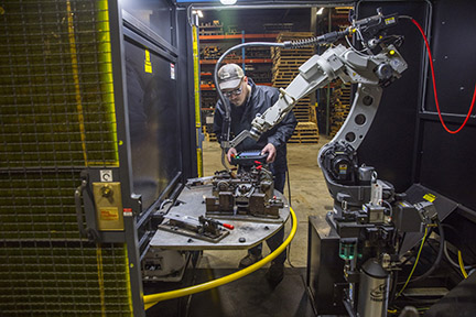
Why robotic welding?
In addition, the national and international marketplace has become increasingly competitive, with companies seeking contracts from any number and any size of business. Investing in welding automation can help set up a company on the path to compete at a global level.Here are additional benefits:
Repeatability is key
Assess the workflow
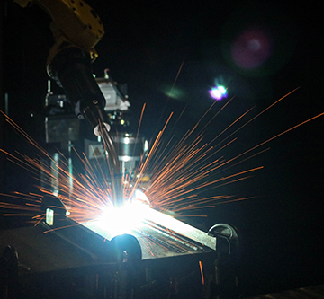
Robotics or fixed automation?
Consider the available space
Integrators and equipment selection
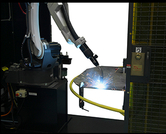
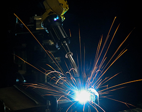
Employee training
Justifying the expense and calculating payback
Improving Welding Automation Safety With Risk Assessment and Training
Improving Welding Automation Safety With Risk Assessment and Training
Robotic welding safety hazards and resources
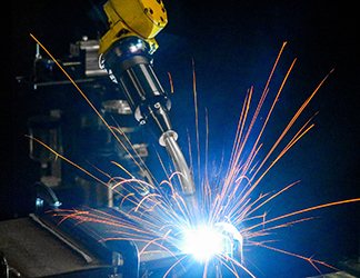
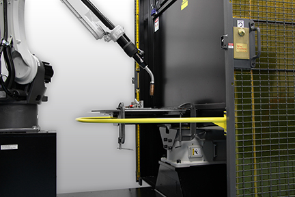
Safe use of robotic welding guns, consumables and reamers
Navigating the robotic welding cell safely
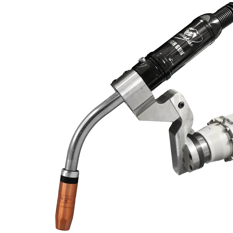
Other safety considerations
Creating a culture of safety
Optimizing Shielding Gas Performance in MIG Welding
Optimizing Shielding Gas Performance in MIG Welding
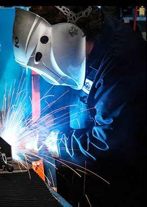
This article was published in The WELDER. To read the entire story, please click here.
MIG Welding Basics: Techniques and Tips for Success
MIG Welding Basics: Techniques and Tips for Success
Proper ergonomics
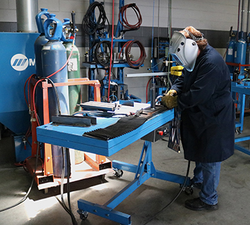
Some ergonomic solutions that can improve safety and productivity include:
Proper work angle, travel angle and movement
When welding a butt joint (a 180-degree joint), the welding operator should hold the MIG welding gun at a 90-degree work angle (in relation to the work piece). Depending on the thickness of the base material, push the gun at a torch angle between 5 and 15 degrees. If the joint requires multiple passes, a slight side-to-side motion, holding at the toes of the weld, can help fill the joint and minimize the risk of undercutting.
In the horizontal welding position, a work angle of 30 to 60 degrees works well, depending on the type and size of the joint. The goal is to prevent the filler metal from sagging or rolling over on the bottom side of the weld joint.
For a T-joint, the welding operator should use a work angle of slightly greater than 90 degrees to the joint. Note, when welding in the vertical position, there are two methods: weld in an uphill or a downhill direction.
The goal when MIG welding overhead is to keep the molten weld metal in the joint. That requires faster travel speeds and work angles will be dictated by the location of the joint. Maintain a 5 to 15 degree travel angle. Any weaving technique should be kept to a minimum to keep the bead small. To gain the most success, the welding operator should be in comfortable position in relation to both the work angle and the direction of travel.
Wire stickout will change depending on the welding process. For short-circuit welding, it is good to maintain a 1/4- to 3/8-inch wire stickout to reduce spatter. Any longer of a stickout will increase electrical resistance, lowering the current and leading to spatter. When using a spray arc transfer, the stickout should be around 3/4 inch.
Welding travel speed influences the shape and quality of a weld bead to a significant degree. Welding operators will need to determine the correct welding travel speed by judging the weld pool size in relation to the joint thickness.Final thoughts
2. Welding Handbook, 9th ed., Vol. 2, Welding Processes, Part 1. American Welding Society: Miami, Fla., p. 184. Implementing Robotic Welding: What to Know to Be Successful
Implementing Robotic Welding: What to Know to Be Successful
Budgeting and ROI
Effective training
Avoid common mistakes

Final thoughts
Preventive Maintenance for Reamers, Accessories and Other Peripherals
Preventive Maintenance for Reamers, Accessories and Other Peripherals
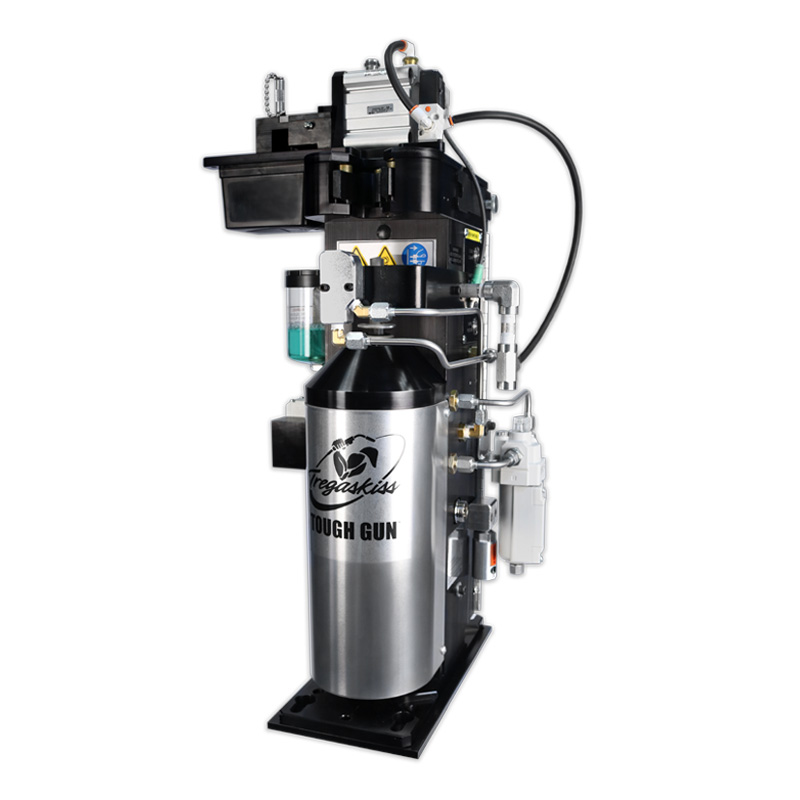
PM tips for reamers and accessories
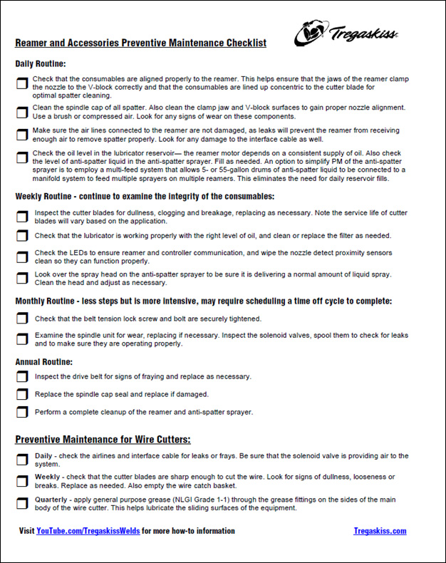
Preventive Maintenance Checklist
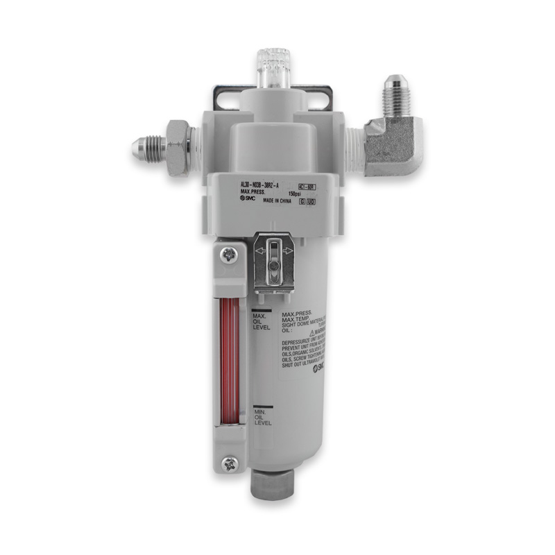
PM tips for wire cutters
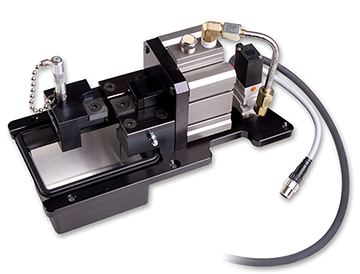
The value of peripherals
Robotic Welding: Troubleshooting FAQs
Robotic Welding: Troubleshooting FAQs
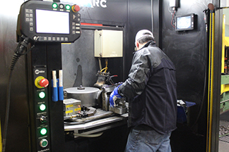
Q: What are causes of poor consumable performance?
Q: What causes poor wire feeding?
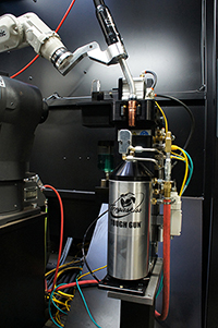
Q: Why is the cable prematurely failing?
Proper cable length is also important. A cable that is too short or too long can be stretched beyond capacity or be prone to kinking.Q: Why is there a problem with tool center point (TCP)?
Q: How do I fix poorly performing peripherals?
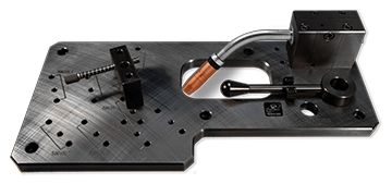
Correcting common problems
7 Tips for Implementing a Robotic Welding Cell
7 Tips for Implementing a Robotic Welding Cell
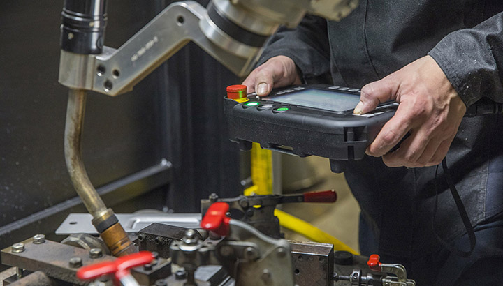
Tip No. 1: Use proper weld settings
Tip No. 2: Choose the right wire
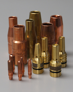
Tip No. 3: Consider the gun and consumables
Tip No. 4: Reduce cable wear
Tip No. 5: Establish TCP
Tip No. 6: Program the robot path
Tip No. 7: Ensure proper fit-up
Closing
MIG Welding FAQs Answered
MIG Welding FAQs Answered
1. What drive roll should I use, and how do I set the tension?
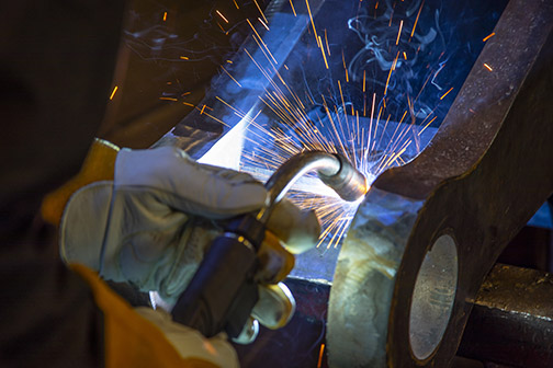
2. How do I get the best results from my MIG welding wire?
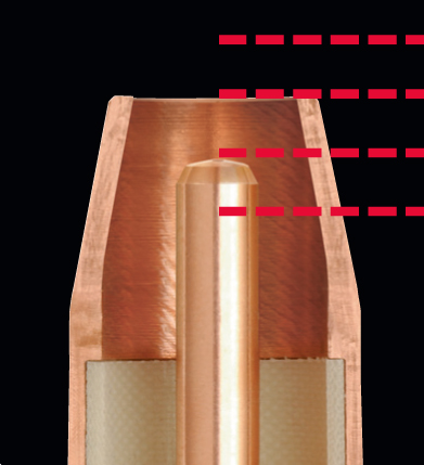
3. What contact recess should I use?
4. What shielding gas is best for my MIG welding wire?
5. What is the best way to control my weld puddle?
5 Common Failures in Robotic Welding and How to Prevent Them
5 Common Failures in Robotic Welding and How to Prevent Them
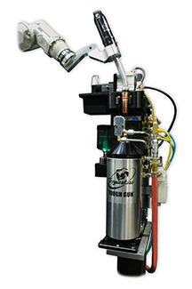
Failure No. 1: Burnback and contact tip wear
Failure No. 2: Broken cutter blades in the reamer
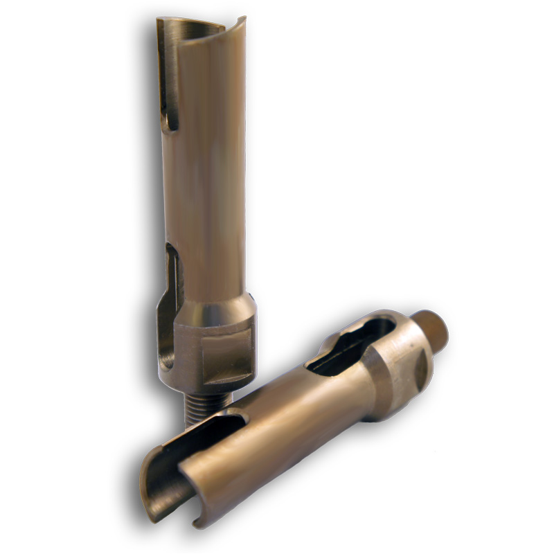
Failure No. 3: Loss of tool center point
Failure No. 4: Broken discs
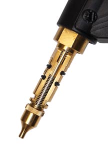
Failure No. 5: Incorrect tool path
Maintenance is key
Anti-Spatter Sprayer: How to See the Best Results
Anti-Spatter Sprayer: How to See the Best Results
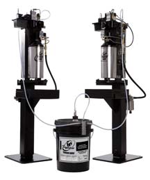
Follow these best practices for anti-spatter liquid usage
The spray containment unit also collects anti-spatter liquid runoff so it can be easily drained into a container and disposed of in accordance with federal, state and local environmental control regulations. Anti-spatter liquid cannot be reused.
Learn more about anti-spatter liquid and available accessories.
This article is the third in a three-part series focused on the use and benefits of anti-spatter liquid. Read article one, Spatter in Welding: Should You Consider Anti-Spatter Liquid? and article two, How to Select and Use Anti-Spatter Liquid.How to Select and Use Anti-Spatter Liquid
How to Select and Use Anti-Spatter Liquid
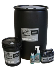
• Easy cleanup and no residue
• Compatibility with the nozzle cleaning station or reamer being usedSafety Tips
Consider these tips:Spatter in Welding: Should You Consider Anti-Spatter Liquid?
Spatter in Welding: Should You Consider Anti-Spatter Liquid?
What is anti-spatter liquid?
• Lowers cost for consumable inventory and management
• Reduces operating costs by improving weld quality and lowering reworkDoes my operation need to use anti-spatter liquid?
Ethernet vs. Standard Reamer: Making the Selection
Ethernet vs Standard Reamer: Making the Selection
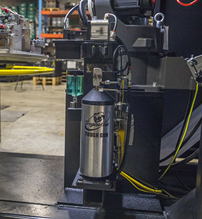
Standard versus Ethernet
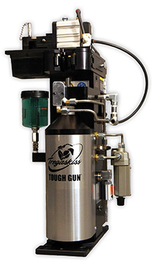
A standard reamer features inputs and outputs that are plugged into a Program Logic Controller (PLC), including the inputs that control the nozzle clamping, cutter actions and anti-spatter spray process.Robotic reamer accessories
Extra: Reamer maintenance
7 MIG Welding Mistakes and How to Avoid Them
7 MIG Welding Mistakes and How to Avoid Them
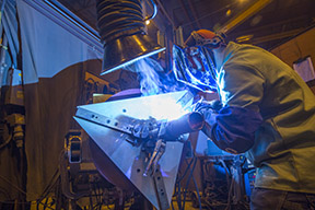
No. 1: Improper liner length
No. 2: Overheated consumables
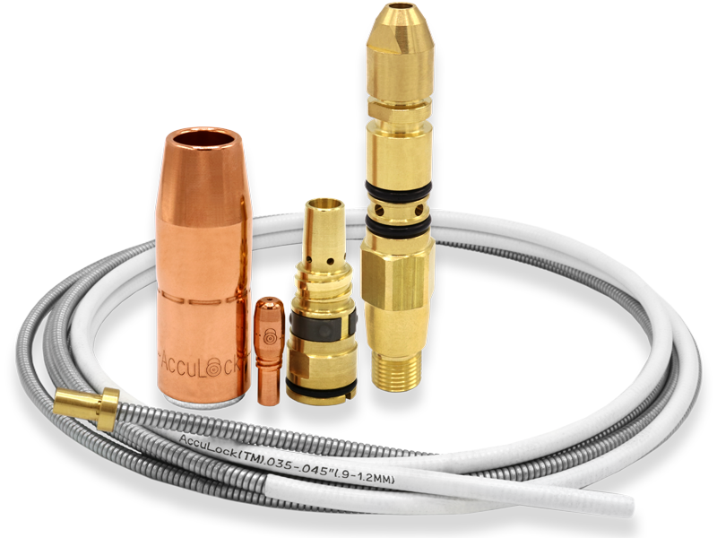
No. 3: A bad ground
No. 4: Improper voltage or wire feed speed
No. 5: Poor cable management
No. 6: Selecting the wrong gun
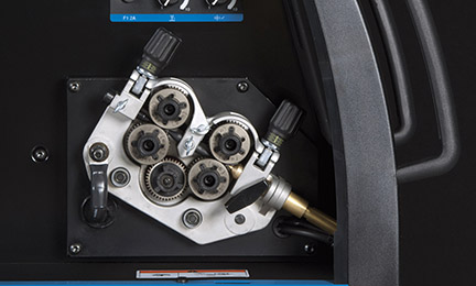
No. 7: Drive roll issues
Proper maintenance is also key
Proper Ergonomics Improve Welding Productivity, Protect Welders
Proper Ergonomics Improve Welding Productivity, Protect Welders
By Jack Kester, senior VP, Marsh Risk Consulting and Andy Monk, product manager, Bernard
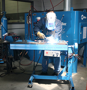
Welding-related musculoskeletal disorders
The risk factors
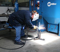
Ergonomic solutions
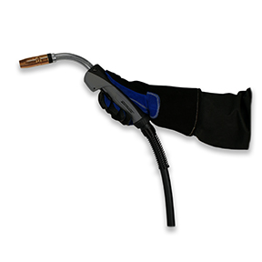
The keys to an effective ergonomics program
Tips to Optimize the Robotic Weld Cell
Tips to Optimize the Robotic Weld Cell
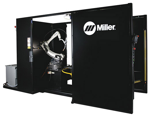
Pre-engineered or custom welding cell?
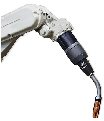
Choosing the right gun and nozzle
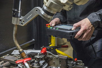
Key considerations for proper layout
The right choices enhance productivity and quality
Signs Your MIG Gun Is Overheating – and How to Prevent It
Signs Your MIG Gun Is Overheating — and How to Prevent It
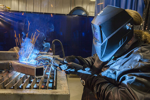
Watch for the signs
Common causes of overheating
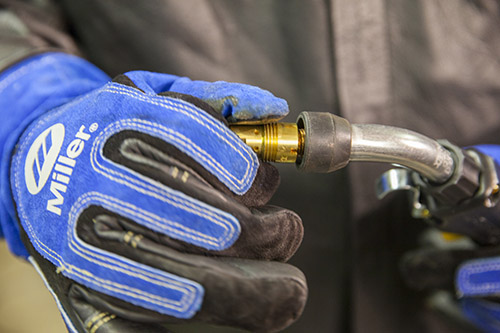
Preventing gun overheating
Reduce Costly Downtime By Preventing Poor Wire Feeding
Reduce Costly Downtime By Preventing Poor Wire Feeding
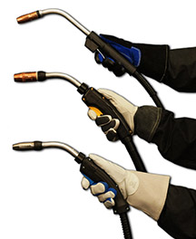
Feeder, adapter and other equipment issues
Drive roll considerations

Check the liner
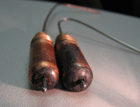
For all consumable systems, inspect the contact tips regularly and replace as necessary.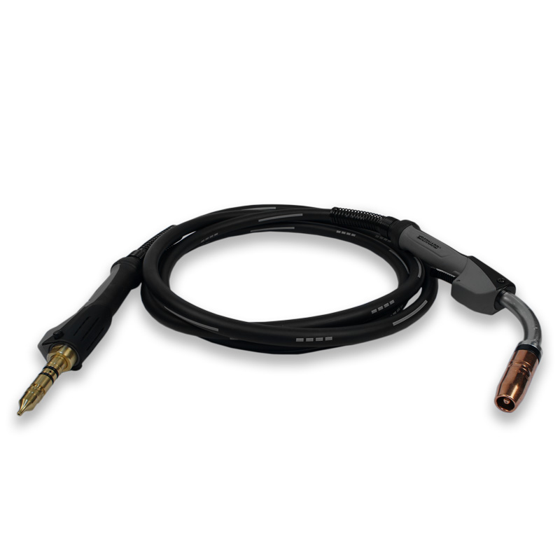
keep the cable as straight as possible during welding to prevent issues with wire feeding.
If the other components and consumables have been inspected and adjusted as needed and wire feeding remains a problem, it may be that the wrong length of gun is being used. Troubleshooting feeding issues
Related Articles
Solving Five Causes of Downtime in a Robotic Welding Operation
Solving Five Causes of Downtime in a Robotic Welding Operation
No. 1: Poor cable management and/or incorrect cable selection
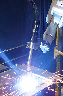
No. 2: Premature consumable failure
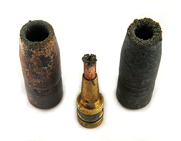
No. 3 Excessive spatter buildup in consumables
No. 4: Collisions
No. 5: Poor wire feeding
Gain Efficiencies and Extend Consumable Life with Anti-Spatter Compound
Gain Efficiencies and Extend Consumable Life with Anti-Spatter Compound
Although it resembles water in its consistency, anti-spatter compound (when applied correctly and in the appropriate volume), will not drip like water. It simply creates a sacrificial barrier between the nozzle and any spatter generated during the welding process; the spatter easily falls off when the nozzle cleaning station performs the reaming cycle, thereby leaving the nozzle and other front-end consumables clean. The compound must be reapplied frequently to help maintain that barrier. tt
Positioning the robotic GMAW gun and front-end consumables in the correct location for the ream cycle and anti-spatter application helps the compound to be applied uniformly. To gain optimal spray coverage, always follow the manufacturer’s instructions for proper setup based on the nozzle bore size. If the sprayer is too far away from the nozzle, it will not provide adequate coverage to prevent spatter buildup. If the nozzle and sprayer are too close, too much spray may saturate the nozzle insulator, which can lead to premature failure.Adding a spray containment unit
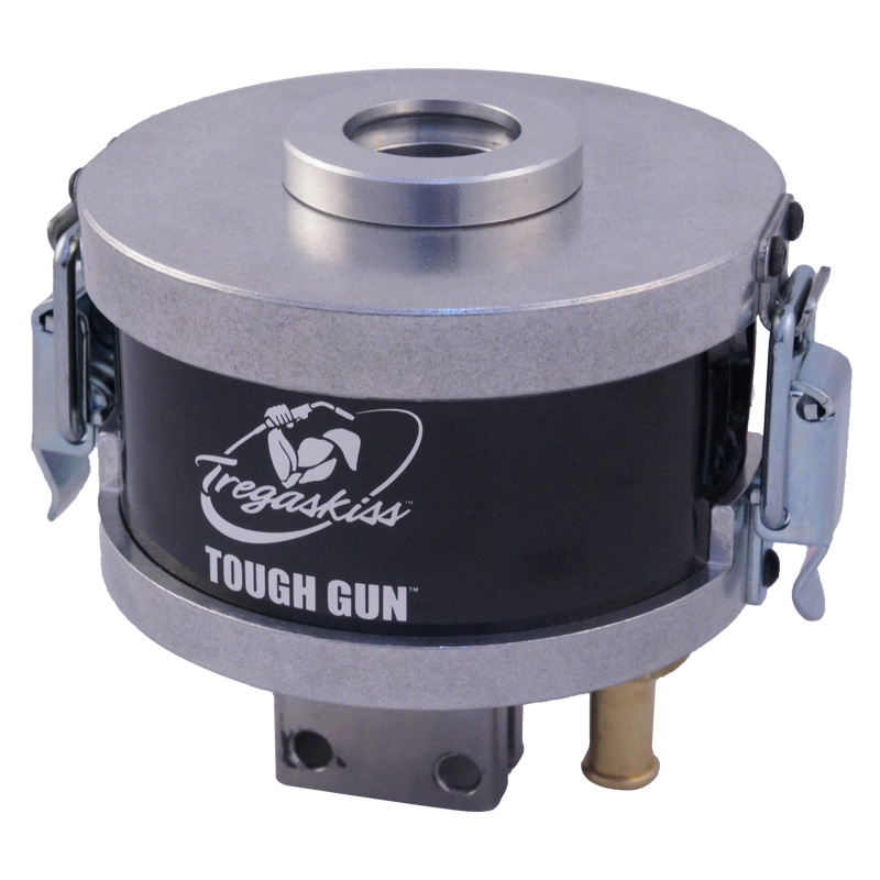
which can help capture excess anti-spatter compound.
This 3- to 4-inch unit fits over the spray head on the
anti-spatter compound sprayer. Additional tips for effective nozzle cleaning station operation
Tips for Optimizing Reamer Usage
Tips for Optimizing Reamer Usage

This article has been published as an exclusive with The Fabricator. To read the entire article, provided by Ryan Lizotte, Tregaskiss field technical support specialist, please click here.
![]()
![]()