Selecting Consumables for Robotic Welding — and Making Them Last
Companies make the investment in welding automation with an eye toward the potential long-term benefits it can provide — better productivity, improved weld quality and reduced costs. Protecting that investment and realizing a quick return on it is as much a matter of planning as it is one of proper equipment selection and usage. That equipment includes everything from the largest components — the robot itself — to the smallest, including the front-end consumables on the robotic MIG gun.

While seemingly insignificant, the nozzles, contact tips and gas diffusers used in robotic welding can have a marked effect on the overall performance of a robotic welding cell.
Frequent changeovers can result in unnecessary downtime and costs. Poorly functioning consumables, or ones that are simply not appropriate for the application, can generate weld quality issues that compound productivity delays and could lead to expensive rework.
Selecting the proper consumables and implementing some best practices for storage, installation and maintenance can help ensure the best results, increase product life and support the benefits sought in welding automation.
General selection considerations
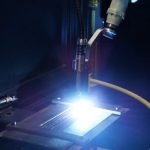
Robotic welding systems typically operate for longer periods of time and at higher amperages than a semi-automatic application, and may utilize transfer modes that are especially harsh on consumables. For example, Pulsed MIG programs — those in which the power source “pulses” between low background currents and high peaks — tend to generate high levels of heat that can erode contact tips more quickly. For that reason, it’s important to select ones that are durable enough for the application.
Contact tips are available in heavy and extended life heavy duty varieties composed of chrome zirconium, and are a good option for gaining longer performance due to their hardness (compared to copper). Typically, machined grooves at the base of the thread are the identifying mark for these types of contact tips.
Selecting nozzles and contact tips that are well-machined with a smooth, consistent surface is key. Smooth surfaces are much less prone to collecting spatter, and therefore more likely to last longer. In some cases, these consumables may not be the least expensive option, but it’s important to weigh out the up-front costs versus the longer-term savings of minimizing changeovers and downtime.
Space and duty cycle factors
Space is always a consideration with robotic welding systems. Fixturing and tooling can limit the ability of the robot to maneuver to a part. Bottleneck, straight or tapered nozzles are common choices to accommodate for those restrictions since they are narrower than standard nozzles and can provide better access. The more tapered a nozzle, however, typically the thinner it is. As a result, it may be less able to withstand higher amperage or higher-duty-cycles commonly used in robotic welding applications. For jobs requiring 300 amps or greater and/or those that have a high level of arc-on time, it may be best to select a heavy-duty style nozzle. These have thicker walls and insulators and are more able to resist heat.
In the end, a good rule of thumb is to select the heaviest duty consumable for the application that still allows access to the tooling in order to make it last the longest. If in doubt about the best choice, consult with a robotic integrator or welding distributor for a recommendation.
Nozzle maintenance
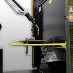
Employing a nozzle cleaning station (also called a reamer) is a good defense against premature consumable failure and poor performance for many different styles of nozzles. A nozzle cleaning station cleans spatter out of the nozzle and clears away debris from the retaining head that tends to accumulate during the welding process.
These stations can also be outfitted with a sprayer that applies a water-based anti-spatter compound to protect the nozzle, retaining head and workpiece from spatter after cleaning.
For the best results, place the nozzle cleaning station close to the robot so it is easily accessible, and program the robot to use it in between cycles (during part loading or tool transfer, for example) so it doesn’t interrupt operation. It should only take 5-6 seconds for the nozzle cleaning station to complete its job and the results are measurable — less spatter and longer consumable life.
Storage and handling
As a best practice, keep consumables in their original packaging until they are ready for use. Opening them and placing them in a bin can lead to scratches or dents that allow spatter to adhere and will ultimately shorten the products’ life or cause them to function poorly. It can also cause dirt and oils to accumulate on the surfaces of the contact tip, which may impede them from properly seating together with the gas diffuser. It can also lead to electrical resistance and heat build-up issues that can, again, shorten their life span.
Wear clean gloves when handling or replacing contact tips, nozzles and diffusers. It helps prevent dirt, oil or other contaminants from adhering to them and leading to premature failure or poor performance. ?Also, keep storage containers for new consumables separate from those for discarded ones to prevent the reuse of a contact tip or nozzle that may have dents or scratches and be prone to spatter accumulation.
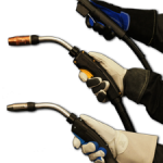
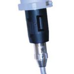
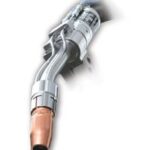
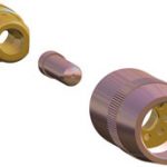
Proper connections
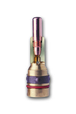
and gas diffuser (as shown in this cutaway)
help ensure reliable electrical conductivity
and minimize heat. The result is more
consistent weld quality and longer-
lasting consumables.
Good electrical conductivity helps ensure consistent arc performance and weld quality, and can help minimize excessive heat and extend the life of the consumables. Installing the consumables properly — according to the manufacturer’s suggestions — and periodically inspecting them for good connections is the best way to ensure that conductivity.
Channel-lock pliers or other recommended installation tools work well to install contact tips and diffusers. Never use wire cutters or side cutters. Too much pressure from these tools can damage the inside diameter of the contact tip, and they can also cause scratches that attract spatter.
A good rule of thumb is to hand-tighten the contact tip until it is fully seated into the diffuser. Next, grip the contact tip with an appropriate tool as close to the base as possible, tightening it one-quarter turn past finger tight. Follow the same procedure for installing and tightening the diffuser so that it fully connects with the neck.
Some contact tips can be installed and held in place by hand-tightening the nozzle. Check the manufacturer’s recommendation for proper installation instructions.
Finally, look for consumables that are designed to fully seat together and mate securely, too, as these can further increase their longevity by minimizing electrical resistance and heat build-up.
As with any part of a robotic welding system, the goal is to keep consumables in the best working order so that the robot is able to continue doing its job. That, in turn, allows companies to spend more time reaping the benefits of the automated welding process and less time troubleshooting problems.
Consumables — contact tips, nozzles and gas diffusers (or retaining heads) — play an important role in the welding process and can impact productivity, costs and weld quality. Many factors influence the selection of consumables, including the application at hand, available budget and more. Some welding operations may view the purchase of consumables as a place to save money, since high-quality consumables typically cost more than lower-quality consumables. However, the up-front cost of consumables is just one part of the picture. Companies should consider the long-term benefits and savings that quality consumables can provide when making the selection, since consumables are an ongoing cost in the welding process. The optimal consumables are ones that provide the best quality and the longest life. These benefits in turn help lower replacement costs, minimize downtime and improve productivity. Also, quality consumables can often reduce post-weld cleanup work, saving time and money. The design, manufacturing process and materials are all characteristics that influence the performance of these components.
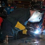
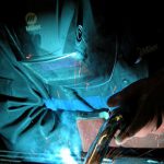
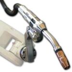
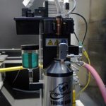
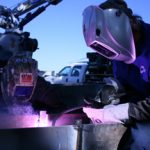
The Occupational Safety and Health Administration (OSHA) and other safety regulatory bodies set the allowable exposure limits for weld fumes and other particulates, including hexavalent chromium, with the aim of protecting employees against potential health hazards in the workplace. Providing welding operators with proper ventilation during the welding process is an important step companies can take to help meet the standards — and to help provide a safe and comfortable work environment. Companies may opt to invest in centralized fume extraction systems, which are designed to protect the entire shop area. These systems involve the installation of new ductwork and fans to remove fumes and are highly effective, but they are also more expensive than other options. A viable alternative for some companies is a fume extraction gun used in conjunction with a fume extraction device or localized filtration system. Fume extraction guns are available in a variety of amperages (typically 300 to 600), cable styles and handle designs. As with any welding equipment, they have their best applications, advantages and limitations, as well as recommended techniques for achieving the best results. Fume extraction guns operate by capturing the fume generated by the welding process right at the source, over and around the weld pool. The weld fumes removed by these guns are composed of a combination of the filler metal and base material. Various manufacturers have proprietary means of constructing guns to conduct this action, but at a basic level they all operate similarly: by mass flow, or the movement of material. A vacuum chamber suctions the fumes through the handle of the gun, into the gun’s hose and through to a port on the filtration system (sometimes informally referred to as a vacuum box). Typically, fume extraction guns are larger than regular welding guns, and include the vacuum and hose that are necessary to extract the fumes. Some manufacturers offer fume extraction guns with a vacuum hose swivel on the rear of the handle to make them easier to maneuver. Also, design advancements have minimized the handle weight and size to make the guns as light as possible for operator comfort, while still offering consistent fume extraction benefits. Fume extraction guns are especially well-suited for applications using solid welding wire and for those in confined spaces, where the goal is to capture fumes immediately at the source, in the welding operator’s breathing zone. Industries where these applications often occur include shipbuilding and heavy equipment manufacturing, as well as general manufacturing and fabrication applications utilizing mild or carbon steel. Petrochemical or other applications where stainless steel welding and greater hexavalent chromium levels are prominent may also present the opportunity to use a fume extraction gun. The guns work well on high amperage and high deposition rate applications. For the best results, fume extraction guns should be used for in-position welding, such as on flat butt welds. In this position, they can most effectively capture fume particles as they rise from the weld pool. It’s more difficult for a fume extraction gun to draw fume particles downward and through the vacuum hose in out-of-position welds, because the fume particles rise at a high rate in those cases. Techniques to maximize performance?The operation of fume extraction guns is similar to that of standard MIG guns, with many of the same recommended best practices. However, there are some techniques that welding operators can follow to help get the best performance from a fume extraction gun. Here are some things to remember: Perhaps the most important tip for maximizing performance is using the appropriate degree of angle. With solid wire — the most common filler metal used with fume extraction guns — use a push technique and an angle of 0 to 15 degrees, which is optimal for fume capture. For flux-cored wire (which generates more fume), use a drag technique with a 0 to 15-degree angle. If the parts are set up at a 0 to 30-degree angle and the gun is kept straight (vertical) during the welding process, the fume rises, allowing the fume extraction of the gun to be maximized. Travel speed during either of these welding processes will typically be dictated by the base metal and the wire size used. Because flux-cored wire produces a slag, it generates more weld fume. However, one benefit of using self-shielded flux-cored wire, for example, is it allows the ability to increase the vacuum level of the gun. Welding operators can close off all the vents and extend the shroud as far as possible. This action maximizes the vacuum at the front end of the gun without concern for disturbing the shielding gas, since there is none generates with self-shielded flux-cored wire. When using gas-shielded flux-cored wire, a 0 to 15-degree angle will help maximize fume collection. At the end of the weld, welding operators can pause for 10 to 15 seconds, holding the fume extraction gun in place without depositing weld metal. This action allows the gun to capture residual fumes as the weld bead is cooling. The contact tip to work distance can be longer — about 1/2 inch to 3/4 inch — when welding with flux-cored wire and a fume extraction gun. With solid wire, welding operators should try to keep the stickout to 1/2 inch or less to maximize fume capture. These lengths are comparable to the stickout lengths used with standard MIG guns. Some fume extraction guns feature adjustable extraction control regulators at the front of the gun handle, while other guns include this function internally. These regulators allow welding operators to increase suction as needed without affecting shielding gas coverage. The ability to balance between the downward flow of shielding gas and the upward flow of the suctioned air is important. Fume extraction guns need to provide the appropriate amount of shielding gas to protect the weld from defects such as porosity without sacrificing the ability to suction fumes efficiently enough to protect the welding operator. Adjusting the air control regulator to the appropriate level can be a matter of trial and error, so welding operators may want to test it on scrap material to optimize the suction rate before welding on a product. As with any piece of welding equipment, fume extraction guns benefit from preventive maintenance. Caring for them is similar to caring for a standard MIG gun. Also note that using flux-cored wire with these guns requires more frequent gun maintenance than solid wire because of the slag and fumes it generates. Regular maintenance is important to help prevent a clog or spatter buildup, which can limit the fume capture rate. Inspecting and maintaining the front end of the gun is key to optimizing fume extraction. Frequently inspect the nozzle and contact tip for signs of spatter buildup, which along with blocking the fume extraction can also obstruct shielding gas flow and cause weld defects. Spatter buildup also can cause consumables to fail prematurely. Replace the consumables if spatter buildup appears, or clean them according to the manufacturer’s recommendations. Also, inspect the vacuum hose regularly for damage such as cuts or kinks, which can lead to loss of suction. Replace a damaged vacuum hose as necessary. Regarding consumables, using the manufacturer’s recommended consumables package with a fume extraction gun helps optimize performance, as the guns are engineered to get the best results with specific consumables. When in doubt about maintenance or any other aspect of using a fume extraction gun, consider working with a trusted welding distributor, certified industrial hygienist and/or the gun manufacturer to address any questions or concerns. In combination with many other variables in the welding operation — wire selection, specific transfer methods and welding processes, welding operator technique, and base material selection — fume extraction guns can help companies maintain compliance with safety regulations and create a cleaner, more comfortable welding environment. Proper use and maintenance of the equipment is important to get optimal results.
Companies invest in welding automation to increase productivity, improve quality and reduce costs. Any unnecessary downtime can quickly interfere with obtaining those goals. But what about small amounts of scheduled downtime for maintenance. In most cases, a well-planned, efficient preventive maintenance (PM) program can yield positive results. Not only does it help ensure reliable throughput, but a properly executed PM program can also lower labor costs, reduce waste and minimize rework. It may even expedite the return on investment (ROI) in the automated welding system. Caring properly for the whole of an automated welding system is imperative, of course, but so too is maintaining the robotic MIG gun. In fact, the robotic MIG gun and its consumables are frequently overlooked components in the system. They are also relatively easy to maintain, and doing so can positively contribute to the efficiency of the entire welding operation. All companies, regardless of their size or arc count, can benefit from regular maintenance of their robotic MIG guns and consumables. The scope of the PM program, however, will vary according to each company’s application. For example, a company with higher-risk applications — those with large, thick parts; long cycle times and/or expensive rework — generally require more frequent care of the equipment than companies that weld smaller, less expensive parts. They simply stand to lose more (in both downtime and money) should something go wrong in the welding process. Most of the maintenance on a robotic MIG gun can be completed shift-by-shift with minimal off-line time. Welding engineers, welding supervisors, tool and die employees or members of the maintenance staff are all viable candidates to oversee the process. All personnel involved, however, need to be properly trained to identify potential problems in the weld cell and learn how to prevent them. They should also be aware that “in-process” maintenance does not constitute the whole of a PM program. Some activities may need to take place off-shift due to their complexity and the time needed to complete them. There are several key components to a good PM program for robotic MIG guns. Before starting any task, it is important to have the correct tools for the job. For example, be sure to have the proper adjustable or crescent wrench for changing diffusers or retaining heads, as well as the recommended pliers, welpers or tip installation tools for installing contact tips. Keep a sharp pair of side cutters on hand, too, to trim the robotic MIG gun liner. These tools help prevent burrs on the liner that can wear or drag on the welding wire. After establishing that the proper tools are in place to support the PM program, consider the following practices. During pauses in production — when the robot finishes welding a part or during routine contact tip changeover, for example — check for clean, secure connections between the MIG gun neck, the diffuser or retaining heads and the contact tip. Also, check that the nozzle is secure and any seals around it are in good condition. Having tight connections from the neck through the contact tip helps ensure a solid electrical flow throughout the components and minimizes heat build-up that could cause premature failure, poor arc stability, quality issues and/or rework. It also reduces the opportunity for burnbacks, which can lead to unplanned downtime for changeover. Look for changes in consumable colors, too, as those are a good indication that they are loose and require tightening. Spatter build-up can cause excessive heat in the consumables and MIG guns, block shielding gas flow, and increase costs for inventory and downtime to change over nozzles, diffusers and contact tips. Visually inspect consumables on a regular basis for signs of spatter, replacing them as needed. Also, consider adding a nozzle cleaning station (also called a reamer or spatter cleaner) to the weld cell. Like its name implies, a nozzle cleaning station removes spatter (and other debris) that builds up in the nozzle and diffuser. Using this equipment in conjunction with a sprayer that applies an anti-spatter compound can further protect against spatter accumulation. Track how long it takes for the liner in the robotic MIG gun to become worn or fouled, and schedule a replacement as needed. Replacing the liner prior to a failure prevents unplanned downtime to remedy wire feeding or quality problems later. Also, always cut the liner according to the manufacturer’s recommendation to prevent kinking and poor wire feeding that can lead to premature contact tip failure and/or arc instability. Periodically, release the drive rolls and check the force required to pull the welding wire from the feeder through the robotic MIG gun. Excessive drag indicates that there is a build-up of debris in the liner and it needs to be replaced. It is best to perform this task in between shifts, as opposed to during contact tip changeover, as it tends to take more time. Check regularly that the welding cable leads are properly secured and assess the condition of the welding cable on the robotic MIG gun. Look for signs of wear and be certain that the cable is not rubbing against any part of the robot’s metal casting, as that friction can cause the cable to loosen or become damaged. A worn spot on the robot (e.g., the absence of paint) or on the tooling is a good indication that the cable is rubbing against it. Rectifying the situation will likely involve repositioning the tooling or a cable management device and may need to occur while the robot is off-line. Still, a quick in-process inspection that identifies the issue can flag it for a later, proactive solution. Preventive maintenance programs don’t have to be complicated — only effective. Most of the robotic MIG gun maintenance discussed here can be completed on a shift-by-shift basis with minimal interference to cycle times and with minimal labor costs. The scope and frequency of a PM program will vary from company to company, of course, but carefully executed maintenance activities can help companies better realize the potential of their automated welding operation. And it can reduce costs by preventing problems, instead of being forced to resolve them.
Worldwide, companies serving the automotive industry have faced a unique set of challenges in the last several years, including changes in material types, a lack of skilled labor and initiatives by OEMs to decrease the weight of vehicles. Still, as the economy continues to rebound, each must find ways to maintain their productivity and profitability — often with fewer employees than before the recent recession. A large part of maintaining that productivity is to ensure high levels of uptime in the robotic welding operations in order to maximize net throughput. It is equally important to find ways to minimize errors and obtain predictive weld data to help anticipate problems in the operation. Conventional issues like spatter, burn-through and poor part fit-up often hinder these attempts, as can the need to manage large amounts of inventory and contend with downtime to service welding equipment. That’s why it’s so important, too, for companies to find equipment that minimizes the total cost of ownership. Unfortunately, there is no single answer to these challenges. There are, however, some considerations that may help reduce automotive suppliers’ pains and assist in other interrelated parts of the process. Best practice meetings: When possible, suppliers in the automotive industry should work with original equipment manufacturers (OEMs) and vendors or welding distributors who can engage regularly in best practice meetings. These meetings can occur by conference call, webinar or in person, and can help determine what practices in the welding operation are working most effectively and what areas need improvement. “Open issues” can be prioritized in order to determine time-phased solutions. These meetings can be especially helpful to companies with multiple locations (even globally), since they help identify opportunities for changes that could positively affect other facilities. They are also an excellent platform for brainstorming error-proofing ideas and serve to open communication among the parties involved in the success of a company’s welding operation. Ultimately, the goal is to spread an assessment of the operation to a broader peer group, extending the company’s core competencies to gain solutions from others’ input. Streamline vendors: Automotive suppliers, particularly those with multiple locations, may want to consider purchasing their robotic gas metal arc welding (GMAW) guns, peripherals, consumables and other welding supplies from a single-source vendor via a welding distributor. Having multiple vendors may appear to provide cost savings on the surface; however, a per-item approach can actually increase the total spend. Instead, by single sourcing a product line, a company is better poised to maximize their purchasing power with one vendor and gain loyalty discounts. The vendor may also be more inclined to aid in new efficiencies and groundbreaking technologies. Plus, a trusted single-source vendor can often help automotive suppliers assess their total weld spend, streamline inventory and reduce costly paperwork. The goal is to work with a vendor who can “own the arc,” providing assistance throughout the whole welding operation by assessing predictive data and offering suggestions for ongoing improvements. “Co-opetition”: If you already work with several welding vendors, co-opetition is your next best option to maintaining an effective welding operation and in some cases can occur as part of best practice meetings. This term refers, in short, to cooperation that occurs between the various equipment manufacturers who are building the end user’s welding solution. Sometimes these companies have competitive product overlap. For example, the manufacturer of the robotic GMAW gun or welding wire may be in direct competition with the company whose power sources are in an automotive supplier’s weld cell. Even so, finding equipment manufacturers who are willing to work together to address problems in the welding operation is key to resolving issues when they arise. A problem with the contact tip, for example, is usually a barometer of other things happening in the process. In short, it is very often a symptom of a problem, as opposed to the root cause. Having partners who are willing to put aside competitive differences for the good of resolving problems like these is important to gaining good welding performance. If this co-opetition is not feasible, companies may want to consider moving to a single-source vendor. Equipment standardization: Recent increases in demand for production have caused some automotive suppliers, especially those in North America, to make capital investments that they previously postponed during the recession. When possible, standardizing on a single brand and style of welding power source, robotic controller, and GMAW gun and consumables during this investment can streamline inventory and maintenance procedures, thereby lowering management costs. It can also help companies avoid long lead times associated with specialty products and improve access to spare parts. For companies in an organic growth mode with new programs and/or greenfield operations, this standardization can help in long-term equipment re-deployment to other facilities, as well as streamline the learning curve among employees, and improve adoption rates and costs. For companies that are in acquisition mode, however, this standardization may not be feasible. Instead, these suppliers should, at a minimum, consider standardizing on a single brand and style of robotic GMAW guns and consumables to minimize inventory. Doing so can also reduce the risk of improper consumable installation, which often leads to unscheduled downtime to rectify. Appropriate welding technology: Many automotive suppliers rely on tandem- welding operations as a means to generate greater productivity. Companies can use this process for line production in the cells housing the majority of the welds. The benefit is that these operations require less floor space and can simultaneously improve throughput. Advancements in single arc pulsed technology have also proven very efficient in providing faster travel speeds and minimizing spatter. This single arc technology, which effectively lowers the average amperage level during welding (by regularly switching the current between high peak amperages and low background amperages), is also quite easy to operate. Given the reduction in workforce in the automotive industry, combined with an overall shortage of skilled labor, this less complex (but highly efficient) technology has already proven beneficial for many automotive suppliers. Companies should work with an appropriate welding distributor or robotic integrator to assess the individual application in order to determine the most appropriate welding technology. Error-proofing: In addition to standardizing equipment when possible, using welding products that minimize the opportunity for human errors is an important part of keeping the welding process flowing. For example, nozzle detection can eliminate the potential of excessive rework or scrap. Avoiding errors in equipment installation is also critical, as missing or incorrectly installed components on the front end of a robotic GMAW gun can cause it to become electrically alive, leading to premature failure and poor welding performance. Preventive maintenance: Even though preventive maintenance or PM may have become a commonplace buzzword in recent years, the fundamentals are still critical to providing good welding performance and reducing unscheduled downtime in the automotive industry. Companies should take care to inspect all connections in the ground cables, feeding assembly, wire feeder, GMAW gun and consumables on a regularly scheduled basis. Replacing worn components during scheduled downtime (at the beginning of a shift, for example) can help prevent problems during production. On some welding robots, “predictive maintenance” technology is available to send alerts when consumables need to be changed. Built-in buffers: As is typical in automotive “just-in-time” applications, suppliers want to reduce work in progress (WIP) — maintaining only strategically determined micro-inventories — and keep parts flowing (Takt time). To continue that workflow but still allow for any instances of stoppage in a robotic welding cell, suppliers may consider building a buffer into production. For example, if a company has a production line of 40 welding robots, breaking that line into fifths (five sections of eight robots), allows them to address any instances of failure while causing a stoppage of only eight robots instead of shutting down production on all 40. That buffer can mean a significant difference in terms of lost production and money. And while no single one of these considerations can ensure the levels of productivity and profitability to which automotive suppliers strive as production demands increase, they can be a step in the right direction. Automotive suppliers should consider working with a trusted welding equipment manufacturer and vendor to discuss a plan for assessing their robotic welding operation and identifying opportunities for improvement.
Robotic welding systems have become an increasingly practical way for companies, large and small, to gain a competitive edge. Assistance with everything from planning and implementation to training is readily available through robotic integrators or vendors, helping make the capital investment less risky and allowing companies to safeguard better results. In addition to programming the robot in a manner that ensures the accuracy, speed and repeatability needed to complete high-quality welds, there are also several steps that companies can take to increase the return on their investment. Saving money on the robotic welding systems is, after all, one of the primary reasons — apart from productivity gains and quality improvements — for implementing this technology. Minimizing downtime, reducing the need for parts replacements and preventing rework are among the more important cost-saving steps companies can make. Here are some ways to achieve those goals. Peripherals — reamers, wire cutters, neck inspection tools and clutches or solid mounts — are all additional equipment that can protect the robotic welding system investment, maximize its effectiveness and reduce costs. This equipment is particularly helpful in minimizing downtime that leads to offline maintenance or repairs of the equipment or its components (e.g., the robotic MIG gun, cables or consumables). Unfortunately, some companies view this equipment as an unnecessary cost and don’t realize that they can play an important role in improving quality and increasing productivity. Peripherals do, of course, require an up-front investment, but the payback period is relatively short. For example, a reamer (also called a nozzle cleaning station or spatter cleaner) minimizes spatter build-up in the nozzle and with it the opportunity for electrical resistance that could lead to premature failure of the robotic MIG gun or consumables. Failure of the gun or the consumable, of course, increases the cost for replacements and requires downtime for changeover — downtime that puts the robot offline and stops it from making parts … and making money. A clean nozzle also allows for good shielding gas flow, thereby minimizing quality issues that could be costly to repair. To protect consumables against costly damage before even placing them on the robotic MIG gun, it is important to employ proper storage and handling practices. Always keep consumables in their original packaging until they are ready for use. Opening the packaging and placing these components in a bin can lead to scratches or dents, both factors that allow spatter to adhere the product and can lead to premature failure. Similarly, removing contact tips or retaining heads from their packaging and storing them in open or dirty containers can cause dirt and/or oil to accumulate on them, which can lead them to seat improperly together. Regularly check that the contact tips, retaining heads and nozzles are securely connected. Solid connections help ensure reliable electrical conductivity and minimize heat, in turn providing more consistent weld quality and helping the consumables last longer. In addition, always follow the MIG consumable manufacturer’s suggestions for installing these consumables and use the proper tools in order to gain the best performance and reduce the risk of damaging them. While these two practices may seem simple, they can go a long way toward minimizing product replacements and preventing downtime that keeps the robot from reaching its optimal throughput during a shift. Both have measurable costs associated with them, as well, and can help companies save money. Preventive maintenance (PM) is another critical way to save money on robotic welding, primarily by preventing unscheduled downtime, poor quality parts and/or costly repairs. It can even help prevent failures that require equipment replacements. The robot, as well as the robotic MIG gun, consumables and cables can all benefit, too. Schedule time to check connections throughout the system (from the front-end consumables through the gun and power pin). This task can easily take place during routine pauses in welding cycles to prevent unplanned downtime. To prevent debris build-up that may affect part fit-up, also remember to clean fixturing on a regular basis. Similarly, check the front-end consumables for spatter build-up and replace as necessary. Verifying tool center point (TCP) is another important cost-saving measure, as it helps ensure that the robotic welding system continues to operate within its proper parameters and provide the same consistent weld quality — repeatedly. Certain maintenance can occur in between shifts, such as cleaning off the robot or changing consumables, for example. Other activities, such as greasing the robot’s joints usually occur less frequently and during a longer scheduled stop. Companies should assess their individual needs and plan the preventive maintenance schedule accordingly. For larger companies, hiring a maintenance crew to take care of preventive maintenance may be desirable. Reducing downtime for routine filler metal package changeovers can be one of the most effective ways of maximizing return on investment and productivity. Ideally, select a package that is large enough to minimize wire changeovers, but not so large that the same wire will remain on the shop floor for more than a couple of days. Filler metal manufacturers typically ship their products in airtight or hermetically sealed containers. Once opened, the wire is at risk of absorbing moisture, dust, oil or other contaminants that can affect its welding performance and ultimately cost money to replace, not to mention downtime to change over. It’s also important to consider the type of filler metal package being used. For instance, recyclable filler metal packaging can reduce costs and labor for properly separating and disposing of recyclable and non-recyclable packaging materials. When possible, stocking an extra filler metal package near the robot can also contribute to cost savings by reducing downtime to transport a new package from the storage area to the weld cell. To prevent problems like bird-nesting (a tangle of wire in the drive rolls) or poor wire feeding — both issues that lead to downtime and added costs — it is important to select the right MIG gun liner and install it properly. Always make sure to have the correct diameter liner for the wire being used. Using too large of a liner for too small of a wire may allow the wire to wander, causing poor wire feeding and/or premature liner failure due to excessive wear. Similarly, if a liner is too small for the wire diameter, the wire will not be able to feed smoothly, resulting in poor weld quality and potentially a clogged liner. Trimming the liner to the correct length is also a good cost-saving measure, since it helps prevent downtime and costs for replacing this part. Some manufacturers print markings on the outside of the weld cable to show when the cable is twisted, providing welding operators the opportunity to straighten it fully in order to measure for the correct liner length. Other manufacturers offer liner gauges as a guide. Both work well to guide in the correct trimming process. There are also spring-loaded modules available that work in conjunction with a front-loading liner to help minimize issues if a welding operator cuts the liner to an incorrect length. These modules are housed in the power pin and put forward pressure on the liner after the welding operator installs it from the front of the gun. They allow up to 1 inch of forgiveness if the liner is too short. Air-cooled robotic MIG guns (rated at 500 amps) operate comfortably in the range of 200 to 300 amps at approximately 60 percent duty cycle with mixed gases. They are good for welding thinner materials — typically upwards of 4 mm thick. The cost of ownership for these guns is usually relatively low since they are easier to maintain and replacement parts are less expensive than water-cooled guns. They work well for shorter welds on high-volume applications and are quite durable, especially through the neck. This durability further reduces costs because it helps the guns maintain their accuracy and create consistent welds. For higher-amperage applications, applications with thicker materials (1/4-inch or more) or those requiring prolonged welding, it’s necessary to have a gun capable of withstanding the increased heat. A water-cooled MIG gun offering 300 to 600 amps of power and 60 to 100 percent duty cycle is a good option to help reduce costs by preventing gun failure or downtime for overheating. These guns cost more to maintain, however, so it’s important to implement a good PM program for them to avoid any costly surprises. Hybrid robotic MIG guns are another option to help reduce costs, particularly when it comes to maintenance. These guns are a mix between an air-cooled and a water-cooled gun, and feature water lines that run independently of the power cable, making them more accessible to repair than on a standard water-cooled MIG gun. These guns can also remain on the robot for maintenance, too, which reduces downtime for removal. Plus, if there are issues with water circulation, these guns can rely on an underlying air-cooled unicable to provide enough current-carrying capacity to avoid a catastrophic failure such as destroying a power cable or other components. Many robotic integrators offer training opportunities not just up front, but also throughout the course of ownership of the robotic welding cell. Because robotic welding systems require properly trained operators to oversee them, it is important to make sure these individuals continue to gain knowledge that will increase their programming, troubleshooting and preventive maintenance knowledge and skills. In many cases, robotic integrators offer online tutorials, troubleshooting information and/or additional on-site training as aftercare support. By taking advantage of such opportunities, it will be easier for those who oversee the robotic welding cell to act quickly should a problem result and get the robot back online to product parts. It also empowers them to take preventive care to prevent downtime in the first place.
Consistent productivity, high quality and low costs are all key components in a successful welding operation. Gaining these advantages depends on everything from the equipment and filler metals to the skill of the welding operators and the techniques being used in the process. The shielding gas also plays a critical role. Both the gas metal arc welding (GMAW) process (using solid or metal-cored wires) and the gas-shielded flux-cored arc welding (FCAW) process require the use of an external shielding gas, each type of which offers distinct characteristics. Knowing how to select the appropriate one for the application can go far in helping obtain the desired welding performance and minimizing the downtime for rework caused by poor weld quality. To help, following are some basics of what you should know about shielding gases. The primary purpose of shielding gas is to protect the molten weld pool against elements in the atmosphere, including oxygen, nitrogen and hydrogen. The reaction of these elements with the weld pool can create a host of problems, including (but not limited to) porosity and excessive spatter. Shielding gas also plays an important role in determining weld penetration profiles, helping maintain arc stability and achieving the desired mechanical properties in the finished weld. Shielding gas can also affect the transfer of the filler metal from the arc to the weld joint, which in turns contributes to the efficiency of the welding process and the quality of the weld. Other important factors that shielding gas help determine include the weld bead appearance, and weld toughness and strength. The four most common shielding gases used in the welding process are carbon dioxide, argon, helium and oxygen. Each has specific characteristics and factors such as cost, available labor (i.e., for weld preparation) and the weld properties desired — all considerations when selecting which shielding gas is best for a given welding application. Carbon dioxide (CO2): This gas is the most common of the reactive gases used in the welding process and also the least expensive of the shielding gases. It is also the only one able to be used without the addition of an inert gas. One of the biggest advantages of pure CO2 is that it provides deep weld penetration, which is useful when welding thick material. It does, however, tend to create a less stable arc and more spatter than when it is mixed with other gases, including argon. This additional spatter can lead to downtime for post-weld cleaning. Pure CO2 is also limited to use in short circuit welding processes. Argon: When welding aluminum, magnesium or titanium, it is common to use 100 percent argon as a shielding gas due to its stable arc features. Adding argon to a CO2 shielding gas is also an option for materials like carbon steel. It provides consistent weld quality and appearance and good weld pool control, and can help minimize post-weld cleanup. Argon also produces a narrow penetration profile, making it useful for fillet and butt welds. Typical mixtures include a balance of 75 to 95 percent argon with 25 to 5 percent CO2. An argon/CO2 shielding gas mixture allows the use of a spray transfer process, which lends itself to high productivity rates and visually appealing welds. Helium: Helium is generally used when welding non-ferrous metals. It is also used in a tri-mix formula of argon and CO2 for welding stainless steels. The gas produces a wide, deep penetration profile, making it suitable for welding thick materials, and also creates a hot arc, which helps increase travel speeds and productivity rates. Helium is typically used in ratios of 25 to 75 percent helium with an appropriate balance of argon. Adjusting these ratios changes the weld penetration, bead profile and travel speeds. It’s important to note that helium is more expensive than other gases and requires a higher flow rate than argon (because it is so light). For this reason, it’s imperative that companies calculate the value of the productivity increase against the increased cost of this gas. Oxygen: Oxygen is a reactive gas typically used in ratios of 9 percent or less. The addition of the gas to a mixture with argon helps to improve weld pool fluidity, weld penetration and arc stability, particularly when welding carbon, low alloy and stainless steels. Because the gas causes oxidation of the weld metal, it is not recommended for use with aluminum, magnesium, copper or other exotic metals. To achieve the best results out of a chosen shielding gas, it’s important to select the proper front-end consumables. These consumables — the gas diffuser, contact tip and nozzle — play a critical role in delivering the shielding gas to the weld pool and also protecting it from the atmosphere. Consider these tips to help with the selection. 1. Choose consumables that have a smooth surface to help resist spatter build-up that could block shielding gas flow and lead to issues, such as porosity. 2. Choose an appropriate size nozzle for the application. A nozzle that is too narrow for the application can easily become clogged with spatter, again, hindering its ability to deliver enough shielding gas to the weld pool to protect it. 3. Consider using nozzles with a built-in spatter guard. These designs add a second phase of shielding gas diffusion, resulting in even smoother, more consistent shielding gas flow. 4. Be certain to select quality gas diffusers to ensure smooth and balanced gas flow. Consult with a trusted welding distributor for recommendations. When your company is responsible for rebuilding, repairing and up-fitting vehicles that deploy to firefighting and rescue situations day in and day out, quality is non-negotiable. Every component must be precisely tooled, every weld precisely placed. The employees at True North Emergency Equipment can certainly attest to that fact. They are a premier service provider for custom fire engines, water tenders, and rescue and emergency vehicles used across the United States, and especially in the Northwest. “Our people understand and believe that our vehicles need to be serviced to complete their mission. They are lifesaving vehicles,” explains Russ Sheldon, operations manager at True North Emergency Equipment. “We don’t just inspect quality into our products. It has to be built in there.” That philosophy spans every aspect of the Hillsboro, Ore.-based company. According to Sheldon, almost every vehicle the company works on is unique, which means it requires the right equipment to work on it – regardless if the job is rebuilt, repaired or upfitted. Recently, True North Emergency Equipment added new MIG welding guns and consumables from Bernard to their welding operation. They found that the products didn’t just stand up to the tough demands of their applications, but that the MIG guns also proved more versatile and comfortable for the welding operators. Plus, the consumables helped reduce their inventory and costs. Not surprisingly, these are benefits that the fabricators and management alike welcomed. In a typical day at True North Emergency Equipment, there are no typical applications. The company could be welding 1/8-inch-thick sheet metal compartments or working on 1/2-inch steel mounting brackets. Most days, fabricators also tackle the nuances of aluminum welding for good measure. Adding to the challenge of welding multiple materials, these same fabricators also find themselves working at awkward angles on a regular basis. According to Sheldon, “Fabricators here weld overhead, vertical and horizontal, and a lot of the components we fixture. So to say we have a standard welding position or a set position … no, that would not be the norm here.” Despite those challenges, the welds have to look, in Sheldon’s words, “sharp.” “Anything exposed has to look top notch. The care in the detail basically has our fabricators’ artistic signature on it,” he adds. Kyle Plock, a True North Emergency Equipment fabricator, has noticed that the company’s new Bernard Q-Gun™ (400 amp) series MIG guns help make that quality easier to achieve — even on out-of-position welds. The gun features a rotatable neck that users can change the position of without any tools. They simply unscrew the durable plastic ring at the base of the neck, rotate the neck to the desired angle and tighten the ring. “With the Q-Gun MIG gun, all you have to do is loosen the neck, turn it and tighten it back up where you want it,” says Plock. “With the old guns, we had to get an Allen wrench, loosen the socket head cap screws, then turn the neck and tighten it back up. So this [gun] is a lot quicker and easier.” Plock adds that this feature comes in handy especially when he’s working on an application that doesn’t allow him a lot of room to maneuver or reach for tools (as would be needed to change neck angles on the older style guns True North Emergency Equipment used). “If we’re inside of a truck in the pump house welding a structure, I often have to turn from one direction to another,” he explains. “If I want this neck to go a different way to fit in a tighter spot, I can turn it without having to twist my hands around.” The addition of a dual schedule switch on the Bernard Q-Gun series MIG guns that the company uses adds to its versatility for fabricators like Plock and the other fabricators. The dual schedule switch allows them to change wire feed settings (without having to go back to the power source) when they alternate between welding thinner and thicker materials. “Personally, I like that if I’m at the top of a truck and need to make an adjustment [to the wire feed speed], I don’t have to climb all the way down to the machine, make the adjustment and then climb all the way back to where we were working,” says Plock. “With this setup here, we don’t have to do that. I just make my adjustment and keep on going. It’s a lot more efficient.” Mitch James, plant manager and field trainer for True North Emergency Equipment agrees that these features and the versatility that his team gets from the new MIG guns is an asset. “The features have made a big difference in comfort and in improving throughput time. There’s just no messing around and adjustment with them,” James explains. True North Emergency Equipment paired its new Bernard Q-Gun series MIG guns with the Centerfire™ consumables system, also from Bernard. These consumables feature a “drop-in,” threadless contact tip that fabricators can change back quickly after a burnback to help reduce downtime and get them back to work faster. The contact tips also have a large diameter tip base and tapered seat that, combined with the gas diffuser, provides better electrical conductivity and heat transfer. For True North Emergency Equipment, those features translate to one single benefit: The consumables last longer than their previous brand. “There was a time when we would have to buy our welding tips 25 or 50 in a bag,” says James. “I actually had team members come to me [before Centerfire] and say they were running through three, four, five, six, eight tips in a matter of just a few hours from burnbacks and such things.” Since the conversion to the Centerfire consumables system, James says that their consumable usage has dropped tremendously. “We don’t have to stock nearly as much anymore. We’re stocking about 75 percent less or about 25 percent of what we used to stock in consumables,” he explains. “That’s saving us quite a bit of money.” It’s all about quality at True North Emergency Equipment — and quality is what keeps the company’s customers and employees happy. The fabricators and management all take pride in knowing that they are helping rebuild, repair and refurbish the best, safest and most durable fire and rescue vehicles for their customers. “Every customer has exacting spec and we suit that need. That’s our niche. That’s who we are,” says Sheldon. “And cater to the high end of the market — always.” That the company has found the right tools to help its employees reach that goal isn’t lost on them, says James. “In the end, it’s all about attitude; emotions; how people feel about what they’re doing. If you feel good, you’re going to do good. So that’s the whole ball of wax right there.”
Your welding operation, just like any other portion of your business, offers opportunities to conserve resources. Consider these 10 money-saving tips for MIG gun care and maintenance as a good first step. And don’t be surprised when you find these tips improve your welding performance along the way! Keep your nozzles, gas diffusers and contact tips in the original package in which they were shipped until you are ready to use them. Doing so prevents scratches and/or dents where spatter can accumulate and cause the consumables to fail prematurely. It also prevents dirt, oil or other debris from adhering to the consumables and inadvertently entering the weld puddle. Remember, proper storage and handling doesn’t just lower your actual costs for consumables, it can also prevent weld defects that require costly rework. Choose the most appropriate neck for your MIG welding application in order to increase comfort and control, and save money. Rotatable necks, for example, adjust without tools so that you can quickly change neck angles by loosening a plastic ring and tightening it once you’ve determined your desired position. These types of necks are especially useful if you find yourself welding on many different applications and angles throughout the day, and they minimize costs for inventory and changeover. For hard-to-reach areas, you may also want to consider a neck coupler, which allows you to connect two existing necks together to extend your reach — again without the cost of purchasing a new or specialized neck. Flex necks are also a good option for saving money, and gaining greater comfort and control, particularly for applications with tighter joints. You can bend these necks to multiple angles to work around corners or get into small spaces without the expense of stocking different neck angles. Regularly perform a visual inspection of your nozzle — inside and outside — to look for spatter build-up. If there is accumulation, either clean the nozzle with a tool designed specifically for the job or replace the nozzle if necessary. During your inspection, also check that the nozzle, contact tip and retaining head are tightened properly, as these components can naturally loosen during welding. Inspecting and tightening your consumables regularly (several times during a welding shift is ideal) help ensure good shielding gas coverage, reliable electrical conductivity and consistent weld quality. Always trim your MIG gun liner according to the manufacturer’s recommendations, using the proper tools and cutting it to the correct length. Too long of a liner can cause kinking, while cutting it too short allows debris to build up between the liner and the gas diffuser. Either way, the wrong liner length can cause poor wire feeding and premature failure of both the liner and the contact tip. When possible, use a liner gauge to determine the proper length for your particular liner and be certain that there are no burrs or sharp edges after you cut it. Also, keep the liner away from contaminants (e.g., don’t let it drag on the floor) during installation and be sure your hands or gloves are clean. These precautions help prevent contaminants from entering the weld puddle and causing costly weld quality issues. Consider using a front-loading MIG gun liner to ease and speed liner replacement. This type of liner cuts installation time nearly in half compared to using a rear-loading liner, saving you downtime and unnecessary labor costs for changeover. Some manufacturers offer a spring-loaded module that works in conjunction with a front-load liner to help minimize issues if you accidentally trim the liner to an incorrect length. These modules are housed in the power pin and put forward pressure on the liner after installing it from the front of the gun. The modules allow up to 1 inch of forgiveness if the liner is too short. There are also jump liners available. These replace only the most commonly worn and clogged liner area — from the neck to the contact tip — to reduce the amount of time a gun is offline and minimize inventory for full-length liners. These jump liners enable quick and easy neck change-out so the MIG gun can be easily adapted to fit multiple applications. When appropriate, switching from heavy-duty contact tips to standard-duty ones can help lower your overall consumable costs, while still providing you with reliable welding performance. If you have lower heat applications, brief arc-on times for short welds or tacks, or if you are using mixed shielding gases and small diameter wires, standard-duty contact tips may be a better option and they cost less. You can also use these types of contact tips if you have applications with restricted access, as the smaller outside diameter can help increase gas coverage and reduce the nozzle’s bore size, making it easier to reach tough joints. Look for non-threaded contact tips that connect or seat securely with the gas diffuser. This type of design provides consistent electrical conductivity and helps dissipate heat more readily. That’s important, since cooler running consumables last longer and provide more consistent performance. A nozzle with a thread-on design helps keep the contact tip centered for better weld placement and it can minimize the opportunity for spatter. This type of design can also withstand demanding jobsite use and abuse. As an additional defense against spatter accumulation, purchase nozzles that have a smooth, non-porous surface. Be sure that the nozzles are free of any sharp edges or flat spots that would further allow spatter to adhere. As when handling the liner, be sure you have clean hands or gloves when you are handling or installing your nozzle. Dirt, oil, grease or other debris can easily adhere to nozzles and later enter the weld puddle, causing weld defects. These contaminants can also cause premature failure of the component. Use the shortest length MIG gun cable possible for your welding application, as it helps prevent kinking and premature wear of both the cable and the MIG gun liner. It also helps prevent wire-feeding problems that could lead to an erratic arc, poor weld quality and unnecessary downtime for rework or consumable replacement. Steel monocoil cables are also an excellent means to prevent kinking. Also, remember to choose the correct diameter liner and contact tip for your welding wire, as this prevents similar problems and helps extend the life of these consumables. Whenever possible, purchase MIG guns and consumables that are backed by a reliable manufacturer’s warranty, and use all guns and consumables as intended so as not to void the terms and conditions. Also, consider the up-front cost versus the long-term savings of purchasing sturdier and more expensive consumables. They will likely last longer, reducing downtime associated with changeover and the cost of the consumables themselves. Keep these tips in mind and you can get back to welding faster… and keep conserving your resources.
Implementing a robotic welding system isn’t something that happens on a whim — at least not successfully. Converting to this technology can help companies gain greater productivity, improve quality and reduce costs in the welding operation, but the process requires thorough planning to gain those results. Working closely with a robotic integrator is a good step to ensure every aspect of the implementation is carefully orchestrated and that the robotic welding system works properly for the given application — in reality, not just theory. Before adding a robotic welding system, it’s helpful to know some key factors that can maximize the return on investment (ROI) in the technology and also help prevent potential problems. The quality of part produced by a robotic welding system depends on the quality of the part that enters the weld cell. That’s why it’s not uncommon to hear the phrase “garbage in, garbage out” when it comes to robotic welding systems — if the part entering the welding cell is flawed, the subsequent weld will be, too. To protect against poor weld quality, it is critical to have simple, consistent parts that allow the robot to execute the weld in the same location, repeatedly. Having a blueprint or electronic CAD drawing is helpful for confirming that repeatability. Robotic integrators can review the blueprint or they may want to create a software simulation that assesses the suitability of the part for the robotic welding system. After the assessment, they can advise of any adjustments that need to be made prior to implementation. Proper fixturing is also critical to achieving part repeatability, regardless of whether the application is high volume/low variety or low volume/high variety. Parts that meet the exact specifications can easily be welded incorrectly if they are not held in an exact position during the process. Many robot manufacturers offer vision systems to aid in part recognition and to ensure that the weld path can be altered in real time if part fit-up issues exist. These systems usually work very well, but may cost more. Robotic welding systems require a properly trained operator to oversee them. A skilled welding operator or an individual with previous robotic welding management experience is a good candidate for the job. Again, a trusted robotic integrator is an excellent resource to provide the necessary training, which should cover proper programming, troubleshooting and preventive maintenance. As a best practice, companies should also consider ongoing training support to keep the operator’s knowledge of the system up to date. In many cases, robotic OEMs offer online tutorials, troubleshooting information and/or additional on-site training as aftercare support. Many facilities already have fume extraction systems in place for manual welding operations, but converting to a robotic welding system may require additional equipment to help maintain a healthy work environment. With the increased production brought forth by a robotic welding system, there is also an increase in fume generation. Given the stringent regulations and recommendations from OSHA (Occupational Safety and Health Administration) and other safety regulatory bodies, proper equipment is necessary to maintain compliance. For larger facilities with higher production robotic welding applications, a centralized fume extraction system is a good option. These systems involve the installation of ductwork throughout the facility and the placement of fume extraction hoods over the welding cell. Smaller shops with fewer robotic welding cells may want to consider a less expensive portable fume extraction system. Operators can wheel these systems right next to the welding cell and adjust the extendable arm toward the robot to suction the fumes. It is also critical that the proper cage and screens are in place around the robotic welding system to protect employees from the welding arc and moving parts within the cell. Adding weld data monitoring capabilities and/or peripherals into a robotic welding system can help improve weld quality and productivity. Achieving these results, however, requires an additional up-front investment. Weld data monitoring (whether integrated in a power source or via a third party) allows companies to track the parameters of individual welds, determine the cause of weld defects and identify general inefficiencies in order to rectify those problems and optimize the process for peak quality and productivity. This equipment requires the purchase of software and computers, as well as the establishment and maintenance of an Ethernet network throughout the facility. Companies will also need tech-savvy individuals to review the data and make the necessary adjustments to the robotic welding system according to the data provided. Similarly, the addition of peripherals — particularly a nozzle cleaning station (also called a reamer or spatter cleaner) can improve weld quality and productivity. By cleaning spatter from the inside of the welding consumables on the front end of the GMAW welding gun, this peripheral helps extend consumable life, reduces downtime for changeover during production and also reduces the cost for replacing consumables. Nozzle cleaning stations also help minimize the loss of shielding gas coverage (due to spatter build-up) that could lead to poor weld quality and rework. Preventive maintenance of the entire robotic welding system, including the robotic GMAW (gas metal arc welding) gun, consumables and cables is an important step in protecting the investment in this technology. Neglecting maintenance can easily lead to unscheduled downtime, poor quality parts and/or costly repairs. It may even lead to failures that require equipment replacements. Scheduling time to check connections throughout the system, clean fixturing (to prevent debris that may affect part fit-up) and check TCP (tool center point) helps ensure that the robotic welding system continues to operate within its proper parameters. Certain maintenance can occur in between shifts — cleaning off the robot or changing consumables, for example — while other activities like greasing the robot’s joints may occur less frequently and during a longer scheduled stop. Companies need to assess their individual needs and plan the preventive maintenance schedule accordingly. For larger companies, hiring a maintenance crew to take care of preventive maintenance may be desirable. Retrofitting robotic welding systems is a common practice among many companies, particularly those investing in automation for the first time or for smaller shops requiring only one or two weld cells. It’s significantly less expensive to purchase a used robot than a new one. When retrofitting a robot, however, it is absolutely essential that it is capable of communicating with the selected power source if companies are to have the entire robotic welding system function properly. New power sources feature software that may not be immediately compatible with a robot that is older, or in some cases, the robot may need a specific robotic GMAW gun that isn’t readily available at a welding distributor or possibly even discontinued. For this reason, it is critical to contact an experienced robotic integrator who can both recommend and help set up all components in the retrofitted robotic welding system. The investment in this assistance can help ensure the proper functioning of the equipment and the long-term cost savings sought by implementing the system. Not to mention, it can also save a lot of frustration and downtime. Robots rely on the input of the operator to execute a given task. That task, however, doesn’t have to be limited to just welding or to welding the same part every time. Operators can program the robot to weld multiple parts over the course of a single shift, enhancing the versatility of the robotic welding system and positioning the company to produce additional output. Operators can also program robots to move parts so that a particular unit is not sitting idle when it isn’t tasked with welding; there are components that offer gripping capabilities and can be installed in addition to a welding gun. Companies may even have a tool dock that allows the robot to be fitted with a different tool and proceed with its work. Some companies with multiple robots may also benefit from installing a vision system in order to check on the work of the others, ensuring that part fit-up is optimal and that the robot is correctly placing welds. Given that the goal of any robotic welding system is uptime, having the versatility to use a robot for multiple tasks can contribute meaningfully to the other advantages of this technology – increased productivity, improved quality, decreased costs — and may help give companies a real competitive edge.
Investing in welding automation can be a relatively quick way for companies to achieve greater productivity, improve weld quality and reduce costs. But protecting that investment is key to maintaining these benefits over the long term. Preventive maintenance (PM) programs are an easy and cost-effective way to help. These programs not only protect against costly downtime, but they can also help lower labor costs, reduce waste and minimize rework. In some cases, they may even expedite the return on investment (ROI) in the automated welding system. PM programs, however, shouldn’t be limited to just the robot or the power source. Protecting your robotic MIG gun and consumables with a PM program is also critical. It can help minimize weld defects, reduce downtime for changeover, and keep the robot up and running longer. Consider these tips to help along the way. There are four key tasks to consider as part of the PM program for your robotic MIG gun and consumables. 1. Check connections on a regular basis. During routine pauses in production, look for secure connections along the length of the robotic MIG gun. Be certain that the MIG gun neck, retaining head (diffuser), contact tip and nozzle are all tight and clean. Also check that the seals around the nozzle are in good condition. Good connections help ensure smooth electrical flow and minimize heat build-up that could lead to poor welding performance and/or premature consumable failure. 2. Regularly inspect the welding cable and power pin. Look for signs of wear on the welding cable and make sure that you have properly secured welding cable leads. Also make sure that the welding cable isn’t rubbing against any part of the robot’s metal casting, as friction can cause the cable to loosen or become damaged. Inspect the power pin, as well, to make sure it is secure. 3. Look for spatter build-up. Regularly inspect the nozzle, contact tip and retaining head for spatter build-up and replace these consumables as necessary. Spatter build-up can block shielding gas flow, leading to poor weld quality, and also lead to premature consumable failure due to a build-up of heat. Ideally, use a nozzle cleaning station (also called a reamer or spatter cleaner) in conjunction with a sprayer that applies anti-spatter compound to minimize spatter build-up. 4. Replace the liner ahead of failures. Track how long it takes for the liner in your robotic MIG gun to become worn and schedule a replacement accordingly. Gauging the life of your liner can help prevent unplanned downtime to address wire-feeding or quality issues resulting from routine wear or clogging. For all preventive maintenance on your robotic MIG gun, be sure to use the proper tools for the job. Robotic MIG gun and consumable manufacturers typically provide recommendations for their products. The frequency and scope of PM activities for your robotic MIG gun depend largely on your application. You should be able to complete most activities, such as checking for secure connections or consumable changeover, on a shift-by-shift basis during routine pauses in welding. Other activities, such as liner replacement, may take longer and need to be completed off-shift. Regardless of whether you weld a high-volume components or larger low-volume assemblies, you should manage the period of time in between routine robotic MIG gun inspections to effectively reduce the downtime required to complete the PM cycle. A small investment of planned down time will mitigate the risk of larger challenges that most often prove more costly in terms of time. For all types of applications, it’s best to develop an initial plan for PM activities for your robotic MIG gun and adjust accordingly until you feel that you have the program that works best for you.
Jolson Welding deals in heavy steel. The company specializes in structural welding for bridge and highway work in one of the most seismically sensitive areas in the world: Northern California. Working with the state department of transportation and local contractors, Bob Jolson (owner, operator, welder) and his team have established welding processes that meet strict code requirements (CalTrans, AWS D1.8 and D1.5), and pass ultrasonic and x-ray tests without fail. A recent job welding soldier pile highlighted the soup-to-nuts mobile welding system that Jolson has built for these applications. A soldier pile is a critical component of many highway projects in Northern California as soil makeup and varying terrain make earth retention necessary. On this particular project, beams of A709 bridge steel will be paired together and placed into holes drilled deep into the ground, serving as the structural backbone for a rebar and concrete retaining wall. Flux-cored arc welding (FCAW) is Jolson’s process of choice. There are structural steel welders who still rely on the shielded metal arc welding (SMAW, or Stick) process due to familiarity; however, flux-cored welding offers a number of advantages in terms of quality and productivity. “If you don’t want to get a lot done in a hurry, stick welding is the way to go,” says Jolson, “but running this process (flux-cored), the deposition rate is really high on it and you get a lot done in a day – probably five or six times more than you would with stick.” Engine-driven welder generator: Big Blue® 500 Voltage-sensing wire feeder: SuitCase® X-TREME™ 12VS Remote control: Wireless Remote Hand Controls Self-shielded flux-cored wire: Hobart Brothers Fabshield® XLR-8™ Self-shielded flux-cored welding gun: Bernard™ Dura-Flux™ Gun 1. Greater productivity through faster deposition rates — the .072-inch self-shielded flux-cored wire used in this application compared to a 7018 1/8-inch stick electrode provides approximately a 249-percent increase in deposition rate in the flat and horizontal positions, and a 162-percent increase in vertical up and overhead positions. 2. Greater deposition efficiency compared to stick electrodes — the flux-cored wire discussed in this case presents a 75-83 percent deposition efficiency versus 65-73 percent in a comparable 7018 stick electrode. 3. Low hydrogen weld deposit (provides resistance to cracking, promotes X-ray quality welds) — the wire used in this application features less than 8 ml/100g of diffusible hydrogen. 4. Welds out of position at high currents, also helping with productivity. 5. Less cleanup through simplified slag removal. Jolson’s power source preference is large-frame, low-speed diesel engine-driven welder generators. Jolson operates a number of Miller welder/generators, including the BigBlue 500. The Big Blue 500 is a CC/CV power source – necessary for flux cored welding – that provides 14-40 volts of welding output in MIG and flux-cored processes. “Our outputs will depend on what positions we’re welding in” says Jolson. “In flat positions we’ll run up around 23 volts and 300 inches per minute (ipm), and when welding vertical-up we run about 230, 240 ipm at about 22 volts.” In addition to providing adequate weld output, Jolson chose this welder/generator for its ability to work at low RPM. “We run the Big Blue engine drives because they run at 1,850 RPM, which helps us keep our fuel economy in check,” says Jolson. “I can get 35 to 40 hours of welding out of one tank of fuel.” Jolson also runs deluxe models that provide 20,000 watts 3-phase power and 12,000 watts 1-phase power in addition to the machine’s standard power. This gives them the ability to run common jobsite tools and accessories, as well as equipment with 3-phase input requirements such as pumps, plasma cutters and portable welders that help turn one machine into a multi-arc work station. “There have been a lot of times where we’re out on a pipeline job and we’ll have to plug in a three-phase pump to empty our ditch and be able to get down in there and do our welding,” says Jolson. “We also use that three-phase power to run our plasma cutters. They cut a lot quicker and everything stays nice and cool, as the duty cycle is increased (with the 3-phase power input power).” To give you an idea of how much welding goes into these structural projects, Jolson and colleague Brandon Hobbs burn through 40 to 45 pounds of wire each day, per man. To simplify inventory and handling, Jolson has standardized almost his entire structural operation on .072-inch Fabshield XLR-8 self-shielded flux-cored wire (AWS E71T-8JD H8). “We stick with the .072 because we could turn it way up or way down, we could weld anything from a handrail to a four-inch thick piece of pipe,” says Jolson. “One wire does it all. And it’s user-friendly. It’s not finicky. You could be a few volts off, or off on your ipm, and it still welds (to standards). ” The primary benefit of a flux-cored wire over a stick electrode is that it is continuously fed, whereas a stick electrode requires the worker to continuously start and stop to replace electrodes. This improves productivity and minimizes the possibility of defects caused by more frequent starts and stops. There is also a higher percentage of lost material with stick electrodes as filler metal in the stub is discarded. As such, 50 pounds of flux-cored wire compared to 50 pounds of stick electrodes would yield a higher deposition efficiency: more of the filler metal is actually deposited into the joint. That efficiency ranges from 75-83 percent with this particular wire compared to 65-73 percent with a 7018 stick electrode (when the product has been burned to a 2-inch stub). “It’s a real high deposition welding wire, and it’s very clean,” says Jolson. “Very seldom do you have any slag inclusions or porosity or anything like that.” The cleanliness Jolson refers to is due in part to easy slag removal. The slag produced by this wire is known to be self-peeling in many cases, improving productivity through less cleaning and helping to prevent potential defects caused by slag inclusions. It also features low levels of diffusible hydrogen (less than 8 mL/100g) and excellent mechanical properties for welding in seismic zones: 58 ksi minimum yield strength, 70 ksi minimum tensile strength, with 22 percent minimum elongation at 2 inches, and impact values of 40 ftlbs at 70 degrees Fahrenheit. “It has really great Charpy V-Notch impact values, and that’s important because of the critical work we do,” says Jolson. One of the concerns that face Flux-Cored welding applications in the field is the consistency of the wire feeding itself. Wire feed speed consistency is important in terms of controlling the deposition rate and heat input into the steel beam – voltage varies with the changing distance between the electrode and the work piece. The new Miller SuitCase X-TREME 12VS voltage-sensing wire feeder ensures wire feed consistency through new robust features and a design resilient to temperature swings throughout the day known to cause variations in feeder performance. “The new feeder is the smoothest feeder I’ve ever ran,” says Jolson. “They have a little bit bigger motor in them, so they don’t get hot throughout the day. (With other feeders), the weather gets hotter and the motor gets hotter in the feeder. The new 12VS is very constant and doesn’t change around. Wherever you put it in the morning, it’s there at the end of the day. There’s no variation.” The new feeder features a new drive motor assembly, motor control and integrated tachometer that provides electronic wire feed speed control and accuracy that rivals the performance of bench-top-style feeders found in shop environments. A new wire delivery system makes it easier to load the 12-inch wire spools and reduces drag on the wire by eliminating the inlet guide and allowing the wire to roll over the large radius of the drive rolls. It also features a new visual scale on the wire pressure knob that eliminates guesswork and allows welders to specifically dial in tension to settings they know provide the best feeding performance for the size and type of wire they are working with. “Having the register on the scale is nice because you always know where you need to be,” says Jolson. “If somebody messes with your machine or puts different wire in it, you just dial it in and you’re up and running. You don’t have to guess and turn it a half-turn and back a half-turn. It makes it really user friendly.” Jolson also claims the feeders allow him to more easily load in new spools of wire, and switch between different wire types/diameters through the elimination of guide tubes within the feeder. “In the old days, we had to change out guide tubes (when changing wire diameters),” he says. “There is no guide tube on this feeder. You just open your feeder, feed your wire through right into the gun, cinch her down and you’re ready to go.” A focus of welding manufacturers has been to put as much knowledge and power into the hands of the welder at the point-of-use as possible. In an application like this, that includes the ability to know exactly what your machine settings are and to change them without having to go back to the welder/generator at the truck. Two technologies that help Jolson with this are digital meters on the wire feeder and wireless remote control technology matched up with the welder/generator. Together, these technologies help improve productivity by allowing welders to more quickly dial in their equipment and get to work faster. “The (wire feeders) without the digital meters, you have to call over to your buddy to tell you where the needle is bouncing around at, and you’re never really accurate that way,” says Jolson. “With this feeder, you can make a practice pass, let off the trigger and look over (at the feeder) and it will hold its values. That way you know where you’re at and you don’t have to bother your partner to come and help you. You can really see them good, too, out in the sun. It’s got some special technology in there that, even out on a sunny day, you can still see your numbers – and that’s nice.” With a voltage sensing wire feeder and CV power source, voltage is set at the power source while wire feed speed (amperage) is set at the feeder. In the past, after running his test pass, Jolson would have to get up and go back to the truck to adjust his voltage. Now, with wireless remote technology, Jolson has full control of that setting without leaving his workplace. “If I’m up on a ladder and I’ve got to change my settings, I don’t want to crawl up and down all day,” says Jolson. “If I’m down in a ditch and I’ve got to turn the machine up and down, rather than spending ten minutes crawling in and out of there, I can turn it up or down and I’m good to go.” Rounding out Jolson’s structural welding system is the Bernard Dura-Flux Self-Shielded Flux-Cored Gun, built specifically for self-shielded flux-cored welding. Rated at 350 amps, these guns feature ergonomic handles, easy-change consumables and a “We like the long goosenecks because it keeps us away from the heat,” says Jolson. “And this sealed microswitch, If you’re out in a dusty environment where it’s laying on the ground all the time, it never gets any dirt or dust in it and it continues to work perfect every time.” “I like the Bernard gun – how you hold it in your hands,” says Hobbs. “You don’t have any fingers that are pressed together, squeezing together, pinching themselves off, getting all tingly and numb. It’s easy to hold and move around. It’s comfortable in the grip of your hand and the trigger guard isn’t too bulky – it does its job without messing you up, without hindering your performance.” Jolson also likes the ability to change out the contact tip without tools – a technology that Bernard calls its Centerfire™ Consumable System. “You take off the little retainer, the tip comes out and you replace your tip,” says Jolson. “And, normally, the tip always wears the top and the bottom, it wears a groove in it. (With these) you can loosen this up, turn the tip 90 degrees, tighten it back down and you’ve got a brand new tip again – so you get two lives out of one tip.” When put together, these varied components build a structural steel welding system that Jolson finds to be optimal for the work he does, ranging from bridge construction to pile splicing. Knowing that all of these components are designed by companies that work together to provide best-in-class, market-focused solutions, Jolson has peace of mind that he’s going to work with the best tools available. “It’s nice because everyone seems to work together,” says Jolson. “If I have a problem with my wire and I’m talking to a Miller representative, they can help me out and vice versa. With Miller, Bernard and Hobart Brothers working together, it really helps us out as end users because everybody knows a little about everything. There’s always somebody there to help you out.”
New industry standards from the Occupational Safety and Health Administration (OSHA) and other safety regulatory bodies have been developed in recent years with one specific objective in mind: to help protect employees against potential health hazards in the workplace. These regulations, which dictate allowable exposure limits of welding fumes and other particulates (including hexavalent chromium), have led many companies to invest in fume extraction equipment. An increased desire to maintain optimal welding operator safety and to attract new skilled welding operators to the field is also a consideration in investing in this equipment — companies want to create the most comfortable and healthy work environment possible. Some companies may opt for centralized fume extraction systems, which are designed to protect the entire shop area. These systems involve the installation of new ductwork Fume extraction guns are available in a variety of amperages, cable styles and handle designs. As with any welding equipment, they have their advantages and limitations, best applications, maintenance requirements and more. In combination with many other variables in the welding operation — welding wire selection, specific transfer methods and welding processes, welding operator behavior and base material selection — fume extraction guns can help companies maintain compliance with safety regulations and create a cleaner, more comfortable welding environment. Fume extraction guns operate by capturing the fume generated by the welding process right at the source, over and around the weld pool. Various manufacturers have proprietary means of constructing guns to conduct this action, but at a basic level they all operate similarly: by mass flow, or the movement of material. This movement occurs by way of a vacuum chamber that suctions the fumes through the handle of the gun, into the gun’s hose through to a port on the filtration system (sometimes informally referred to as a vacuum box). The welding fumes that these guns remove are composed of a combination of the filler metal and base material.Some fume extraction guns feature adjustable extraction control regulators at the front of the gun handle, which allow welding operators to increase suction as needed (without affecting shielding gas coverage), while others provide this function internally. Regardless of the manner, the ability to balance between the downward flow of shielding gas and the upward flow of the suctioned air is critical. The fume extraction gun needs to provide the appropriate amount of shielding gas to protect the weld from defects such as porosity, without sacrificing the ability to suction fumes efficiently enough to protect the welding operator. The balance allows the weld pool time to react and solidify, and gives the fume particles time to decelerate so they are easier to extract. Typically, fume extraction guns are larger than regular welding guns and tend to be bulky due to the vacuum and hose necessary to extract the fumes. For that reason, some manufacturers create fume extraction guns with a vacuum hose swivel on the rear of the handle to make them easier to maneuver. Manufacturers have also, since fume extraction guns were first introduced (in the late 1960s and early 1970s), found ways to engineer internal components to minimize the handle weight in order to reduce operator fatigue. Fume extraction guns are well-suited for applications using solid welding wire and those in confined spaces. These include, but are not limited to applications in the shipbuilding and heavy equipment manufacturing industries, as well as general manufacturing and fabrication. They are also ideal for welding on stainless steel applications, as this material generates greater levels of hexavalent chromium, and on mild and carbon steel applications. The guns also work well on high amperage and high deposition rate applications and are available, typically, in 300 to 600 amp ranges. For the best results, fume extraction guns should be used for in-position welding, such as on flat butt welds. In this position, they can most effectively capture fume particles as they rise from the weld pool. In out-of-position welds, the energy of the fume particles causes them to rise at a high rate, making it more difficult for the fume extraction gun to draw them downward and through the vacuum hose. One distinct advantage to fume extraction guns is that they remove the fumes at the source, minimizing the amount that enters the welding operator’s immediate breathing zone. However, because welding operators typically move the gun away from the weld pool after completing a pass, the fume extraction gun is not as able to control residual fume as well as a fume extraction hood can. As with any piece of welding equipment, fume extraction guns benefit from preventive maintenance. Caring for them is similar to caring for a standard GMAW gun. Regularly check for tight connections throughout the length of the fume extraction gun to ensure good electrical flow. Minimizing electrical resistance helps ensure consistent weld quality and prevent premature failure of the front-end consumables — contact tip, nozzle and diffuser. Frequently inspect the nozzle and contact tip for signs of spatter build-up, too, as such build-up can obstruct shielding gas flow and cause weld defects that ultimately will need to be reworked. Spatter build-up can also cause consumables to fail prematurely. Replace the consumables if spatter build-up appears or clean them according to the manufacturer’s recommendation. In some cases the shroud that surrounds the nozzle may also have to be replaced or cleaned free of spatter. To ensure optimal fume extraction capabilities, inspect the vacuum hose regularly for damage, including cuts or kinks that could lead to loss of suction. Replace a damaged vacuum hose as necessary and dispose of it according to the manufacturer’s and/or an industrial hygienist’s directions. Visually inspect the handle for cracks or missing screws, and also check that the gun’s trigger is not sticking or otherwise malfunctioning. Replace or repair these components as necessary. Finally, maintenance on the liner is also important. As with the vacuum hose, use compressed air to clear out any potential blockages during welding wire changeovers or when removing the wire from the gun. Spending an extra few minutes clearing out any debris from the liner can save considerably more time than troubleshooting the weld defects and equipment problems that can result from blockages. Also, track the amount of time that it takes for a liner to wear during the course of the welding operation. Replace the liner prior to that in the future to prevent downtime for replacement during shifts or problems with wire feeding or quality. When in doubt about maintenance or any other aspect of using a fume extraction gun, consider working with a trusted welding distributor, certified industrial hygienist and/or the fume extraction gun manufacturer to address any questions or concerns. Proper use of this equipment can help provide optimal results, and improve the safety and comfort of the welding environment.
In the fabrication and manufacturing world, quality and productivity are everything. To remain competitive, companies need to look continually for ways to increase throughput and minimize defects, while also keeping costs low for parts and labor. In many cases, turning to robotic welding is a means to achieve those goals — for both the smaller job shop and larger manufacturing facilities. The decision to implement a robotic weld cell, however, takes a good deal of consideration and planning if the system is to function in the most efficient, productive and profitable manner. And it requires a significant investment. Fortunately, the long-term benefits of a robotic welding operation can be very positive. For companies who have already invested in robotic welding, but are looking to improve or better understand their operations, or for those considering the investment, it is critical to consider some key factors about the technology. Here, we will explore “what you must know about robotic welding” to make the most of the process. Justifying the cost of a robotic weld cell comes down to the ability to gain (and prove) a payback on the investment. Typically, that payback comes in the form of greater productivity and higher-quality welds (which minimize instances of costly and time-consuming rework), but there are other contributing factors to the return on the investment (ROI) in this technology. Robotic welding also offers the advantage of lower energy and labor costs, and in many cases lower material costs due to fewer instances of overwelding. Overwelding is a common and costly occurrence in semi-automatic welding. A weld bead that is 1/8-inch larger than necessary can double filler metal costs, but a robot can reduce those costs by only putting down as much material as necessary. Plus, robotic welding systems use bulk filler metals (600-pound drums, for example) that companies can often purchase at a greater discount. For companies just considering the investment in robotic welding, it is important to consider how to calculate the payback. Assess the current part cycle times and compare those to the potential cycle times of a robot. A trusted robotic welding integrator or OEM can often help with this calculation. During this process, also consider the possibility of reallocating existing labor to other parts of the welding operation, where these individuals can add value to the process. Remember, up to 75 percent of the cost in a semi-automatic welding operation is labor. If there is the opportunity to use that labor elsewhere to increase part production, the payback on the investment in robotic welding will increase. Most companies — particularly smaller ones or those with frequent production changes — seek a payback on the robotic welding investment of no greater than 12 to 15 months. That time frame is entirely possible to achieve with proper up-front planning of the part blueprints, fixturing and general setup of the system. In some cases, companies may be able to justify a longer payback period if they know that their production needs will remain relatively static for longer periods of time. The output from a robotic welding cell is only as good as the parts fed into it. In order to gain the advantages of these systems, it is critical to have accurate, repeatable part designs. Gaps, poor fit-up or poor joint access all prevent a robot from completing its job correctly. The best part designs for a robotic welding application are simple ones that allow the robot to execute the same weld repeatedly. High-volume applications with low-variety parts are especially poised to gain the advantages of robotic welding. Companies should try to avoid part designs that require intricate tooling or clamping to hold it in place, as both can hinder the efficiency of the robot and also add to the up-front cost of the operation. That said, in some cases, companies may still be able to gain a good payback on the investment in tooling for slightly more complex parts, but they will need to weigh out the pros and cons of that cost ahead of time. Companies also need to be certain to assess their overall welding operation for consistent process flow. Bottlenecks upstream can easily slow down the movement of parts into the robotic work cell and the ability of the system to function to its full capacity. A robot that sits idle costs time and money. Some companies may need to reconfigure operations or set up a flexible cell that can manage quick tool and fixture changes in order to minimize bottlenecks in the process flow. It is also important to have adequate labor to supply the robot with parts. Again, companies should consider tapping the knowledge of a robotic welding integrator for advice and assistance to optimize process flow. The robotic MIG gun and consumables on a robot together are responsible for directing the current to the arc to complete the weld, making them integral components in the whole system. To gain the best quality and to avoid expensive downtime for maintenance, repairs or replacement, companies need to select a robotic MIG gun that is suitable for the amperage, duty cycle and cooling capacity needed in the application. Using a robotic MIG gun that offers inadequate cooling or amperage can cause performance issues and lead to premature failure — both factors that increase costs and downtime. Likewise, using a robotic MIG gun that offers higher amperages than necessary raises the total cost of ownership, as typically the cost of a robotic MIG gun increases directly in proportion to its amperage. Companies also need to select their consumables — contact tips, nozzles, retaining heads (diffusers) and liners — carefully and manage them properly in order to gain optimal productivity and lower costs. Look for contact tips with more mass at the front end and that are buried further in the gas diffuser — both features help the tip resist heat from the arc. Consumables with tapered connections mate securely together to provide good electrical conductivity, which also reduces heat buildup and helps the consumables last longer. Contact tips with long tails and coarse threads are also a good option to simplify installation — they virtually eliminate cross-threading because the tail concentrically aligns the contact tip within the diffuser before the threads engage. This easy-to-install design works well for operations with less experienced welding operators who may not be as familiar with consumable changeovers. It also helps reduce unplanned downtime for troubleshooting associated with cross-threading.t As with robotic MIG guns, carefully matching the type of consumables to the application can keep companies from having to address premature failures and/or accrue costly downtime (not to mention, lapses in production). It can also keep them from overpaying for consumables that may be too much for the application. Companies should also consider the mode of welding when selecting consumables, as technology such as Pulsed welding tends to be especially harsh on consumables and often requires heavy-duty options to withstand the heat of the arc for longer periods of time. For these applications, look for contact tips that are engineered with a hardened insert, making them more resistant to arc erosion and wear. They typically last 10 times longer than copper or chrome zirconium tips. Companies can regain as much as 95% of lost productivity for contact tip changes with this style by reducing planned downtime for the task. Peripherals refer to any additional equipment integrated into the robotic welding system to maximize its performance. They include items such as a nozzle cleaning station (sometimes called a reamer or spatter cleaner), anti-spatter sprayers, wire cutters and neck alignment tools. Unfortunately, some companies downplay the value of peripherals, viewing them as an unnecessary cost, and don’t realize that they can play an important role in reducing downtime and rework, improving quality and increasing productivity. Consider a nozzle cleaning station, for example. As its name implies, this peripheral cleans the nozzle of dirt, debris and spatter, typically during routine pauses in the robotic welding operation. This cleaning action helps prevent shielding gas coverage loss that could lead to weld defects, expensive rework and lost productivity. The equipment also helps the front-end consumables last longer — and longer consumable life means less downtime for changeover and less expense for replacements. The addition of an anti-spatter sprayer further improves consumable life and performance by adding an anti-spatter compound that serves as a protective barrier against spatter buildup and other contaminants. In the long run, the up-front investment in peripherals such as these can lead to measurable savings and provide a better return on investment by aiding the robot in doing what it does best: complete consistent, high-quality welds for longer periods of time than a semi-automatic welding operation. Robotic welding operations require ongoing supervision and maintenance, and that job needs to be completed by a skilled operator who has undergone the proper training. When considering an investment in robotic welding, companies should take care to evaluate the available pool of talent. As a rule, skilled welding operators and/or employees with prior robotic welding experience are the best candidates to supervise the weld cell. After the proper training, which a robotic integrator or OEM can typically provide, these employees can provide the necessary operating and troubleshooting skills to ensure the maximum uptime in the robotic welding cell. As part of the routine training, it is absolutely necessary for the operators who will be overseeing the robot to be able to schedule and perform routine preventive maintenance on the system. Implementing preventive maintenance helps minimize unnecessary downtime and keep the robotic welding system running more smoothly. If problems can be solved before they arise and the robotic welding equipment made to last longer, it can protect the company’s investment, and ensure the productivity and profitability sought by this equipment in the first place. Companies should consider vetting robotic welding integrators to determine the availability and costs associated with the training of personnel. Typically training lasts one to three weeks, depending on the certification level desired, and continuing tutorials are often available. In the end, careful planning, good equipment selection and proper training are all “must-knows” for managing a profitable and productive robotic welding operation. So whether a company is new to robotic welding or trying to improve an existing operation, knowing some key factors can go a long way in helping to gain a competitive edge and to make the most out of the investment.
The term “ergonomics” has become increasingly common in the workplace as companies strive to improve safety and efficiency among employees — whether in the office or on the plant floor. At its most basic level, ergonomics refers to the discipline or science of designing equipment and arranging the work environment for optimal worker comfort and productivity. Minimizing fatigue, reducing repetitive motion, and decreasing overall physical and mental stress are some of the key factors at the heart of it. For welding operators who spend their time maneuvering around difficult weld joints with a MIG, flux-cored or fume extraction welding gun and facing a hot arc, the term takes on an especially important meaning. A welding gun’s handle, neck and power cable design can significantly impact the duration of time a welding operator can weld without experiencing fatigue or stress. So too can the heat generated in the process. Excessive heat, just like musculoskeletal strain, can contribute negatively to the welding operator’s health and efficiency. In the long run, choosing a welding gun that offers greater comfort and operates at a cooler temperature can help increase productivity and, ultimately, the profitability of the welding operation by allowing for greater arc-on time. When welding, the first factor in good ergonomics is to select a welding gun with the appropriate handle design. Typically, manufacturers offer handles in curved and straight designs, one or the other of which may be more comfortable for a given welding operator to hold and control. The preference is individual and a welding operator may need to experiment to determine which design best suits him or her. If possible, a welding operator may want to consider using a slightly lower-amperage welding gun to gain greater comfort and minimize fatigue and/or stress on the wrists and hands. Typically, as a welding gun’s amperage decreases, so too does the size of the gun handle, which makes the equipment lighter and easier to maneuver for longer periods of time. It is important, however, that in selecting a smaller and lighter-weight handle, the welding operator still has a gun that meets the application’s amperage and duty cycle requirements. Duty cycle is defined by the amount of arc-on time in a 10-minute period that the equipment can be operated at maximum capacity. Some welding guns will offer 100 percent duty cycle, while others are rated 60 percent or below. In many cases, a welding gun rated at 300 amps, for example, may suffice for a 400-amp application considering that welding operators rarely weld continuously enough to exceed the gun’s duty cycle. In a shop setting, another option to gain greater comfort and productivity would be to convert to a water-cooled welding gun for MIG applications, as these guns are generally smaller, lighter and easier for welding operators to manage for longer periods of time. Smaller, shorter and lighter power cables offer greater flexibility to welding operators, making it easier to maneuver the equipment without excess stress on the wrists or hands. A good rule of thumb is to select the smallest and shortest power cable possible that can still meet the needs of the application. Smaller, shorter power cables can also minimize clutter in the weld cell by preventing excessive coiling and minimizing tripping hazards. Less clutter and coiling also reduces the chance of poor wire feeding that could cause downtime and hinder productivity. On fume extraction guns, look for vacuum hose swivel on rear of handle, as this feature improves flexibility and reduces welding operator fatigue. Many MIG and flux-cored guns are available with rotatable and flexible necks in various lengths and angles. These types of necks allow the welding operator to select one that will best suit the joint access required for an application. For example, rotatable necks are a good option for welding out of position, even overhead. They do not require the welding operator to change the welding gun handle or position, so he or she can hold the gun in a way that is most comfortable, while also gaining access to the weld joint. Similarly, flexible necks can be easily adjusted to fit different welding angles and reach difficult joints that may be restricted or otherwise awkward to reach. This feature also helps minimize straining to reach a particular weld joint, and with it reduces the opportunity for fatigue or injury. Some welding gun manufacturers also offer neck couplers. These accessories allow the welding operator to connect multiple necks together to reach especially difficult joints more comfortably. Increasing productivity in a welding operation by way of improved ergonomics is a matter of more than just having lightweight, easy-to-control equipment. It’s also a matter of minimizing heat stress in the work environment. When welding materials such as aluminum or stainless steel, there is an opportunity for greater radiant heat — heat that reflects from the welding arc and base metal back to the handle. Welding operators can use a longer neck on the welding gun to place the handle further back from the arc when welding on such applications. Also, the addition of a neck grip on a MIG gun can protect the welding operator from heat exposure and related fatigue. These high-temperature silicon rubber grips slide over the neck and offer the added benefit of increased control. They allow welding operators to rest the neck on their hand or forearm, using it as a pivot point to maneuver the MIG gun more comfortably. In the end, having equipment that is easy to operate during the welding process is the first step in achieving good ergonomics, a safe work environment and greater productivity. After all, a more comfortable welding operator is a more content one. And more content employees can help companies generate greater throughput on a day-to-day basis. Start the process by finding welding guns that are lightweight, offer an appropriate handle and neck design, and feature the right neck and power cable for the job and for the welding operator.
Automated welding systems add speed, accuracy and repeatability to the welding operation. They can help operations increase productivity and reduce costs in a relatively short period of time. But these results don’t happen by accident; they require careful equipment selection, system integration and training — including the selection of peripherals. Peripherals refer to the additional equipment that is integrated into the automated welding system to maximize its performance. The selection and implementation of the proper peripherals should be a part of the welding automation plan upfront, not later after the system is in place. Incorporating peripherals early in the process can result in more efficient throughput, long-term cost savings, better quality welds and minimized downtime. Consider these frequently asked questions about peripherals to clarify their role in the welding operation and better understand their benefits. A nozzle cleaning station (also called a reamer) cleans spatter from the inside of the welding consumables on the front-end of the MIG welding gun, including nozzles, contact tips and retaining heads. There are several benefits a nozzle cleaning station can offer. First, by keeping the nozzle clean, this equipment helps reduce the risk of losing shielding gas coverage that could potentially lead to expensive re-work. Secondly, it helps lengthen the life of the consumables (nozzle, contact tip and diffuser or retaining head) and the robotic MIG gun. Longer equipment life translates into less downtime and also less cost for equipment — both factors that contribute positively to a company’s ROI of its automated welding system. An anti-spatter compound (typically in liquid form) can provide additional protection to consumables. A sprayer applies the anti-spatter compound to the front-end consumables after they have been cleaned. In many cases the sprayer can be mounted on the nozzle cleaning station, integrating it into the overall process of nozzle cleaning. Recall that the rule of “less is more” applies. Excessive anti-spatter usage can lead to unnecessary costs and the compound may build up on the nozzle, the welding robot and the parts being welded. In the long term, a high spray volume could cause additional problems that are just as harmful as spatter build-up itself. How can a wire cutter help the operation? Many robotic welding applications require consistent welding wire stick-out (also called electrode extension) when the arc initiates. A wire cutter can help maintain that consistency. As its name implies, a wire cutter cuts the welding wire to a specified length and it also removes any inconsistencies at the end of the wire, resulting in more reliable and smoother arc starts. For companies that program their robot to seam track (or find the joint) through touch sensing, the consistent wire stick-out allows for more reliable and repeatable welds by helping the robot to more easily locate the correct spot to begin welding. Most wire cutters are capable of cutting different types of welding wire, including stainless steel, flux-cored and metal-cored, usually up to 1/16-inch diameter. Companies may prefer to mount the wire cutter on a nozzle station or locate it remotely, according to their needs.?? This peripheral verifies that the robotic MIG gun’s neck is set to the intended tool center point (TCP), allowing it to be readjusted after a collision or if the neck becomes bent due to routine welding. Most inspection fixtures will accommodate standard necks for a particular brand of robotic gun. After determining the tolerances for the program, a trained welding operator simply adjusts the neck to meet the correct specifications. This adjustment helps prevent costly rework due to missing weld joints and can help prevent the downtime to reprogram the robot to meet the welding specifications with the existing bent neck. For companies that maintain a large number of robots, a neck inspection fixture can also help prevent confusion when exchanging necks from one robotic MIG gun to another. Welding operators simply remove a bent neck, exchange it with a spare that has already been inspected and adjusted, and put the robot back in service immediately. The damaged neck can then be set aside for inspection while the robot is still online. In cases where collision detection is integral to the robot, a solid arm mount can help protect against a collision. As its name implies, a solid arm mount is just that: solid. It does not provide electrical feedback during an impact, but rather relies on the software to stop the robot during an impact. For robots without collision detection, a clutch may be added to the system. The function of a clutch is both mechanical and electrical. It recognizes the physical impact of the collision and then sends an electrical signal back to the robot controller, causing the system to stop. This action prevents damage to the robot and the robotic gun. It also alerts the welding operator overseeing the operation that there is an incorrect variable in the weld cell.Both clutches and solid arm mounts require mounting arms to attach them to the robotic MIG gun and hold it in a specified position, so the robot can repeat the same weld throughout the welding process. These mounting arms are generally composed of a durable aluminum alloy that can resist breakage during an impact. Although the addition of peripherals to an automated system does add to the initial cost of automating, this equipment can lead to measurable savings in the long term. Since the goal in automated welding is repeatability and increased productivity, any additional equipment that can help achieve that result is worth the consideration.
When your company focuses on custom contract manufacturing, you have to be prepared for any job that comes through the door — no matter how complex or challenging. Don Kammerzell, owner of K-zell Metals, Inc. in Phoenix knows that firsthand. And he’s grown a successful business out of it. “We do the jobs that nobody else wants to do… or can’t. And we’ve made a good practice out of it.” he explains,. “Everyone in the area knows that they can rely on us to work with most any material and on most any design.” Those jobs come, 99 percent of the time, by word of mouth from K-zell Metals’ suppliers and customers, and include everything from building horse race starting gates to fabricating limited edition silicon bronze playground sculptures and components for military vehicles. In addition to custom forming, laser cutting and CNC press brake equipment, K-zell Metals also has two robotic welding cells that combined allow the company to create more precise assemblies and to maintain a more competitive edge than when it relied solely on semi-automatic welding. According to Kammerzell, the robotic welding cells have allowed the company to increase its throughput significantly in recent years — manufacturing as many as 5,000 parts in a single run — while still maintaining the same overhead. As part of the robotic welding systems, K-zell chose to implement a hybrid air- and water-cooled robotic MIG gun from Tregaskiss called the TOUGH GUN I.C.E.® robotic MIG gun. I.C.E. stands for Integrated Cooling Enhancer, a feature that allows water circulation to the nozzle, keeping the front-end consumables running cooler and lasting longer. K-zell Metals can now easily switch between welding thick and thin parts without the hassle or downtime of replacing the entire gun. When Kammerzell and his team decided to invest in their robotic welding cells, the goal was to gain a 15 to 20 percent increase in productivity and reduce costs for their customers and for themselves. Favorably, they found out that they could do better than that and the quality of the parts was even better than expected. They also found that the need to develop precise, repeatable parts was absolutely critical. “Having the robotic weld cells forces our laser and press brake operations to be absolutely perfect, because they’re automatically checked every day.” Kammerzell explains, “Every part has to be right in order to fit in the fixture, so the robots are like built-in quality control for us.” To ensure the accuracy of its parts and fixturing, K-zell Metals relies on their Bystronic Bystar 4020 laser cutting equipment and also employs three mechanical engineers who design the fixturing and tooling for their robotic weld cells. K-zell Metals also relies on its welding team to implement precise welding parameters for every run of parts, fine-tuning them to the point of producing parts that, according to Kammerzell, are “essentially 100 percent – right out of the box.” The time, effort and labor needed to refine the company’s robotic weld cells, however, have paid off — literally. K-zell Metals gained a full return on the automation investment within two years. When it came time to decide which robotic MIG gun to implement the robotic weld cells, Kammerzell deferred to Jim Benjamin — K-zell Metals’ quality assurance manager, who also happens to be a welding engineer and the company’s robotic welding supervisor. Benjamin had previously worked for an OEM supplier of robotic welding equipment and was familiar with Tregaskiss products. “In my experience, I found the Tregaskiss products to be exceptionally durable. And I knew that they were backed by great customer service. That made my choice to pick the TOUGH GUN I.C.E. [robotic MIG gun] an easy one.” Given that the company welds on such a variety of parts, materials and thicknesses, Benjamin wanted a robotic MIG gun that could accommodate it all. The TOUGH GUN I.C.E. robotic MIG gun is a hybrid between conventional air- and water-cooled designs that does just that. It features stainless steel water lines that run along the outside of the gun’s neck down to the nozzle, rather than through the neck like true water-cooled products. This design provides water circulation that keeps the consumables running cool, and it simplifies maintenance. When welding thicker parts, Benjamin explains, the welding operator uses the I.C.E. neck and hooks it up to an external water cooler within the robotic welding cell. The addition of the water-cooling allows the company to weld at the higher amperages required when welding these parts or when welding for longer periods of time (i.e. on long, continuous welds). When they weld thinner parts, he simply changes over to an air-cooled neck. “I like the interchangeability of the air- and I.C.E. [water-cooled] necks. It gives us a wider variety of applications that we can put on the same robot, with the same power source and in the same weld cell.” explains Benjamin, “Plus, the gun features a quick change neck, so we can swap them out without a lot of downtime.” Benjamin also appreciates the safety and durability of the TOUGH GUN I.C.E. robotic MIG Gun. In the event of a crash, he explains, the gun has excellent safety features that prevent it from becoming damaged. He also uses a simple neck alignment tool to ensure that the neck maintains its tool center point (TCP). “If there happens to be a crash, we can put the neck in the alignment fixture and be back up and running in just a few minutes.” he explains, “We don’t have to tweak the robot — we can get right back in production.” To both Benjamin and Kammerzell, having equipment that can keep up with the unique demands of their customer base is non-negotiable. “Being a job shop and a contract manufacturer, we never know if we are going to have 10 parts, one part or several hundred,” Benjamin says. “Having a gun we can so easily swap out and maintain is a huge benefit.”
Robotic welding systems, when implemented properly and for the right application, can add great value to a welding operation. In addition to offering faster speeds and greater productivity, robotic welding systems can improve weld cosmetics, reduce rework and repairs, lower materials costs by limiting overwelding and also reduce labor costs. The consistency of these systems and the typically rapid return on investment (ROI) make them especially appealing for companies looking to gain a competitive edge. Still, setting up a robot and selecting its components — the consumables and the gun, for example — can be a complicated business, especially for first-time users. In fact, the simple question of whether to automate may itself be confusing to a company that hasn’t used a robotic welding system before. For insight into welding automation, consider these answers to some of the most frequently asked questions. High-volume, low-variety applications are well-suited to robotic welding; however, lower-volume, higher-variety applications may also work if implemented with the proper tooling. Companies will need to consider the additional cost for tooling to determine if the robotic welding system can still provide a solid return on the initial investment. In either case, it is critical that the application have simple, consistent parts so that the robot can repeatedly execute the weld in the same location. Having a blueprint or electronic CAD drawing is helpful. Robotic integrators can review the blueprint or create a software simulation that can assess the suitability of the part for welding automation. These assessments can not only help to visualize the quality of the part to be welded, but they can also identify ways to fine-tune tooling to optimize the process. Workflow is also important. Companies should be certain to have a high enough flow of parts to the robotic welding cell for the application so that it can operate consistently. Delays in upstream parts fabrication can cause bottlenecks that result in costly downtime. Each type of automation has its own best applications. Fixed automation is an efficient and cost-effective way to weld simple repetitive straight welds or round welds, where the part is rotated. It is good for high volume applications of a single part. Fixturing for fixed automation can be expensive, however, so companies will need to factor that cost into the initial investment and determine whether this type of automation is still cost-effective for the long-term. They also need to determine if future jobs will require retooling, as that will add further to costs. For companies wishing to have the flexibility to weld on multiple applications, a robotic welding system is a better choice. Because a robot can be programmed for multiple jobs, it can often handle the task of many fixed-automation systems. Robotic welding systems require a trained operator. Skilled welding operators or those with previous robotic welding management experience are good candidates. The person overseeing the robotic welding system should be able to program it, troubleshoot errors and perform preventive maintenance. Robotic OEM manufacturers can often provide the appropriate training for employees who are new to welding automation. It is recommended to look for ongoing training support. Some robotic integrators or welding solutions providers offer online tutorials, troubleshooting information and/or additional on-site training as part of their aftercare support. In many cases, yes. It is absolutely necessary, however, to ensure that the air-cooled robotic MIG gun is rated at a high enough amperage and duty cycle for the application. For example, an air-cooled robotic GMAW gun rated at 500 amps with 60 percent duty cycle using mixed gases will be capable of welding continuously for 6 minutes (out of an available 10 minutes) at about 350 amps. When welding with pulsed waveforms it is very important to review the peak currents and ensure they do not exceed 350 amps at any time during the welding process. Air-cooled MIG guns offer the advantage of being less expensive — both to purchase and maintain — but if a company anticipates longer periods of welding or higher amperage needs, it may be necessary to shift toward a water-cooled gun. There are also “hybrid” robotic MIG guns available in the marketplace. These guns feature a durable neck similar to an air-cooled MIG gun, but offer the higher cooling capacity of a water-cooled model by way of exterior water lines. These guns can be easier to maintain than a standard water-cooled MIG gun and typically offer 300 to 550 amperage welding capacity at 60 percent duty cycle (using mixed gases), making them adequate to weld on a variety of applications. The style of consumables — contact tips, diffusers (or retaining heads) and nozzles — depends entirely on the application. Ideally, the consumables should be durable enough to last the duration of a robotic welding shift to help minimize downtime for changeover. High-amperage applications (over 300 amps) with high levels of arc-on time can often benefit from heavy-duty consumables. Chrome zirconium products are a good choice. For lower amperage applications or applications with short arc times, standard-duty consumables (often copper) are appropriate. Companies also need to consider the access required to reach the weld joint. In some cases, it may be necessary to use a bottleneck, straight or tapered nozzle, all of which are narrower, to maneuver around tooling or into complex areas. It is equally important to consider the mode of welding being used. For example, pulsed welding programs can be especially harsh on consumables due to the higher levels of heat that the process generates. These applications can benefit, often, from heavier-duty consumables. Touch sensing, sometimes called joint touch sensing, is a software system that employs the welding wire or nozzle to help locate the joint in a robotic welding application. This software allows the robot to store position data and send electrical impulses back to the controller once it has located the joint. For applications that have slight variations in parts, touch sensing helps maintain weld consistency. It is also more cost-effective than investing in new tooling and fixturing to hold a part in a precise location; if the part moves slightly, the robot can still locate the joint and weld accurately, as long as the joint has well-defined edges. Touch sensing does add a few seconds to the cycle time, but it is a good choice especially for companies welding large, thicker parts that would be costly to rework should the joint be welded poorly. To gain optimal results, it is a good idea to combine touch sensing with a robotic MIG gun that has a wire brake feature. The wire brake holds the welding wire in a set position while the robot articulates and searches for the weld joint, ensuring more accurate touch sensing readings. ? It is always advisable to add peripherals, particularly a nozzle cleaning station (also called a reamer or spatter cleaner), to a robotic welding system. This peripheral cleans spatter from the inside of the welding consumables on the front end of the MIG welding gun, including nozzles, contact tips and retaining heads. It helps extend consumable life, and with that, reduces downtime for changeover during production and also the cost for replacing consumables. Nozzle cleaning stations also help reduce the risk of losing shielding gas coverage (due to spatter build-up) that could potentially lead to expensive re-work. Adding a sprayer provides additional benefits, too. This peripheral can be mounted on the nozzle cleaning station and works by applying an anti-spatter compound to the front-end consumables after they have been cleaned. This compound coats the inside and outside of the nozzle, and also the contact tip, creating a protective barrier between the consumables and spatter. The payback on a robotic welding system can be relatively quick in many cases. To determine it, companies need to assess their parts volume, as well as the amount of time it takes to weld those parts manually, and compare that information to the potential cycle times of a robotic welding system. Determining this volume is critical, given that labor comprises 75 percent of the cost of a manually welded component. Even if a company produces the same amount of parts, labor could be reallocated elsewhere to increase productivity and enhance the payback on the robotic welding system. Companies should also calculate the savings for overwelding often associated with semi-automatic welding applications. A weld bead that is 1/8-in. larger than necessary can often double filler metal costs. Because robots are more precise in their placement, companies should calculate the potential savings for filler metals when calculating payback. Because robotic welding systems use bulk filler metal drums that require fewer changeovers (and sometimes have the perk of bulk purchasing discounts), that savings can also be considered. As always, when companies encounter problems with a robotic welding system or have questions about a program or component, it’s best to contact a trusted robotic integrator, welding distributor or welding equipment manufacturer for support. Robotic welding systems aren’t cheap and companies should never take chances with their investment by guessing about the right course of action. The right information is the best way to gain productivity, quality and cost improvements from a robotic welding system.
Rapid growth is a problem many companies would love to have. Those that experience it, however, must properly manage that growth in order to maintain profitability and avoid the potential pitfalls of taking on more work than they are equipped to handle. Communications systems, training protocols, material flow and inventory management are just a few of the areas that Miller Welding and Machine Co., Brookville, Penn., has refined over the last 1 1/2 years as its workforce nearly doubled and it expanded from one to three manufacturing facilities. As a subassembly fabricator for top-tier OEM manufacturers of cranes, aerial work platforms, mining and other heavy equipment, Miller produces dozens of different components across 140 semi-automatic welding cells and 10 robotic cells. From an inventory management perspective, fabricating and welding such a wide variety of products has required Miller to standardize their applications as much as possible on the same tools and equipment. Minimizing operator downtime and maintenance costs has also been essential to managing their rapid growth. Miller addressed all of those challenges with the help of Bernard Centerfire™ consumables and Q-Gun™ MIG guns. Centerfire consumables have reduced operator downtime and allowed the company to standardize all of its welding guns, regardless of brand, on one set of consumables. Bernard’s Q-Gun line of MIG guns also has reduced operator downtime and lowered the company’s maintenance costs through a combination of durability and time saving technology. Founded in 1962 as a small welding and machining shop serving the needs of the Pennsylvania steel industry, Miller Welding and Machine has grown into a major component fabricator with nearly 500 employees and state-of-the-art manufacturing facilities. “Taking advantage of technological advances has been one of the keys to our success,” explains Dave Miller Sr. “Not long after I started the business, a welding distributor told me about a new technology called wire welding. It seemed to be a natural fit for some large welds we were doing, so we jumped into the wire feeding business and never looked back.” Today, Miller’s son, Dave Miller Jr., serves as company president and continues his father’s tradition of using technology to achieve process and product improvements. One of the technologies heralded by Dave Miller Jr. has been the addition of vending machine-style inventory management systems from which nearly all of the company’s consumables are distributed. The use of these systems, combined with standardizing the company’s operations on Centerfire consumables, has reduced inventory costs and simplified the company’s inventory control procedures. The vending system requires employees to enter a unique employee number and then the part number of the consumable they need. The machine then records the information and dispenses the products. Miller uses nine of these vending machines throughout its three plants, each of which is linked in to a mainframe computer that tracks nearly all of its consumable products, including fasteners, batteries, grinding wheels and more. To further simplify the stocking, tracking and ordering system, Miller also sought to reduce as much as possible the number of welding consumables they carried. Bernard’s Centerfire consumables fit perfectly with this goal. Because Centerfire consumables — diffusers, contact tips and nozzles — are able to be installed on most major brands of MIG guns through the use of conversion parts, Miller was able to stock one set of welding consumables in the vending systems for the three different brands of MIG guns used throughout the plant. Standardizing on one brand of welding consumables has reduced the potential for operators to select the wrong consumable for their gun, simplified the purchasing department’s inventory tracking and ordering processes and reduced the amount of space that their welding consumables consumed in the vending system by 66 percent. “It keeps everything simple,” explained Production Manager Dave Moore. “We’re in the welding and fabrication business, not inventory management, so anything we can do to reduce the amount of time and money spent managing our welding consumables inventory is time and money we can devote to our core competencies.” The key to managing Miller’s growth has been the Centerfire system’s unique design, which has reduced operator downtime, increased consumable service life and offered excellent weld quality and consistency. The Centerfire system features non-threaded contact tips that fit securely in the diffuser and lock into place without the use of tools. This allows operators to change contact tips in about half the time it takes to change out a threaded tip. At an average of 1 minute per tip change, and 2.5 tip changes per welding cell per month, Miller saves roughly six man-hours each month just in the time it takes to change the contact tips. The Centefire system further reduces operator downtime by requiring fewer changeovers. Miller averages over 240 man-hours per contact tip, compared to most brands, which need to be changed an average of every 24 – 48 man hours. “At one of our facilities we have about 80 arcs running two 10-hour shifts plus an eight-hour shift on Saturdays. They weld material anywhere from 1/4-in. — 2-in. and they put down over 30,000 pounds of wire a month. For all that, they usually go through about 200 contact tips per month,” Moore said, “so we’re very satisfied with the performance and durability of the Centerfire tips.” Like all of its equipment and tools, Miller’s use of Bernard Q-Guns is a decision based on what works rather than brand loyalty. The company initially received the guns as part of a package with their wire feeder purchases, so, as Moore puts it, “we weren’t about to throw them in the trash and put something else on.” If the Q-Guns hadn’t performed up to the company’s standards, however, “we’d have run them until they died, trashed them and replaced them with something else,” Moore said. But they did perform well, and the company has converted nearly all of its hand-held MIG welding to Bernard Q-Guns. The company has been very satisfied with a different brand of guns for its robotic applications, and there are still a few hand-held guns of a third brand that are still in service, but will be replaced with Q-Guns once they wear out. “These guns have been very cost effective for us,” Moore said. “They hold up well, the repair and replacement costs are very reasonable and they offer a wide variety of configurations, so we can get the exact gun that we need for all of our applications.” Miller uses 400-amp Q-Guns with a short neck angled at 45 degrees and mostly 15-foot cables, which the company is able to customize 24 hours a day through Bernard’s online Configurator. The Configurator can then be used to order the customized gun through the company’s preferred welding distributor. They also take advantage of the available Bernard Jumpliner™, which allows operators to reduce the time it takes to replace a worn liner from an average of about 20 minutes down to around 90-seconds. The Jumpliner is a replacement liner that allows operators to only replace the most frequently worn out portion of the liner — the section leading from the consumables back through to the gun’s handle — rather than replacing then entire liner when only a small section is worn out. Just as importantly, Miller encountered virtually no resistance from its welders. “There wasn’t really an adjustment period in getting used to the new guns,” Turntable Welder Brody Speer said. “The guns are lighter and more maneuverable than other products we’ve used, so they were well received right from the start.” With a welding system in place that allows Miller Welding and Machine to handle nearly any type of welding job without changing the guns, consumables, wire or processes they use, the company has used technological advancements to position itself to manage the growth they’ve already experienced, and also to continue growing into the future.
Anyone in a job shop environment knows how much downtime accrues from changing over a welding cell to accommodate different product runs. For Wisconsin-based OEM Fabricators, that downtime added up to $2,000 a day until it adopted the “rule of ones,” which standardized their welding processes, and implemented lean manufacturing concepts back in 2004. OEM is a job shop that specializes in fabricating components and assemblies for over 80 heavy equipment manufacturers across 20 industries, primarily the oil patch, oil exploration, power generation, and crane industries. Serving that many customers and meeting product runs from 1 to 250 units per run, welding operators at OEM had to regularly change welding processes, change wires, change gases and change other variables to accommodate each new product runs. The inefficiencies created by these changeovers, however, didn’t mesh well with the company’s philosophy. “Our goal is to be an extension of our customers,” explains Manufacturing Engineer Scott Exner. “We provide the services and products that they choose not to manufacture internally, so they need to be able to come to us and receive a quality product, on time, at a fair price.” That’s why the company adopted a “rule of ones” welding system — one process, one gas, one wire, one gun — as part of its implementation of lean manufacturing. With Bernard Q-Gun™ MIG guns and Centerfire™ consumables as an integral part of that implementation, OEM was able to reduce their downtime and expand their welding operation two to three times its size since implementing the welding process standardization approximately three years ago. OEM significantly reduced the potential for quality variance between welding operators and greatly reduced the time it took to do initial hiring training for it welders. OEM was not experiencing a manufacturing crisis when it began implementing lean manufacturing principles in 2004, but as a continuously forward-looking company, they saw the potential offered by becoming lean. “Integrating lean concepts in our operation has allowed us to look at all of our processes and how they’re interrelated,” Exner explains. “We might have as many as 20 people touching a product as it moves through the fabrication process. Lean principles help us provide our employees with the best information and the best tools to do their jobs as effectively as possible.” Providing their customers with a consistent and high quality product has been one of the foundations upon which OEM has built its reputation. One of the toughest parts of upholding that reputation has been establishing uniformity and consistency between their 115 welding operators while also reducing downtime and rework. Although it took only about 15 minutes for operators to change over from welding one product to another, the frequency of changeovers combined with the number of welding stations in the plant added up to a significant amount of time. “When you make that changeover in a multi-process mode,” explains Exner, “you have to change to a different wire, different gas, and then go through and re-setup your process parameters. All of that takes time and creates the possibility for inconsistency.” That’s when they began investigating the potential to standardize all of their welding operations on a single process, wire, gas, gun and consumables. The manufacturing flow and improvements and the savings that resulted are part of the reason OEM has been able to dramatically increase its size in a short period of time with two plants in full operation. For their process, OEM selected an advanced pulsed MIG process from Miller Electric Mfg. Co. that is able to monitor the arc and adapt the current thousands of times per second, allowing OEM’s welders to simply pull the trigger and weld while the power source ensures the correct output is produced. For the wire and gas, OEM selected a .045 ER70S-6 solid wire with a 90/10 Argon/CO2 mixed gas. The high argon content helps produce a very stable arc and allows the system to produce a spray transfer for high deposition and a calm weld puddle. When it came to selecting the one gun and consumables package that would handle nearly all of their manufacturing needs, OEM chose Bernard Q-Guns with Centerfire consumables. “When we first started integrating lean principles and standardization into our welding operations, guns and consumables were right at the top of our list,” Exner said. “We looked at a lot of different packages, but so far nothing has matched the Bernard Q300 gun and Centerfire consumables.” In fact, Exner said he still reviews competitive guns and consumables on a yearly basis, and he has yet to find a product that provides a better result for their applications. “We brought in guns from other manufacturers and sat down and wrote out a comparison listing what we liked and disliked about each gun,” Exner said. “There were some things we liked better on the other guns, but in the end, the Bernard Q300 was the whole package.” One of the biggest benefits Exner saw in the Q-Gun was its ability to be custom configured to meet the needs of a variety of different applications within their shop. Bernard’s 24-hour online Configurator allows customers to build a customized MIG gun by individually selecting each component, from the contact tip to the power pin, based on their specific needs. The Configurator can then be used to request a price quote from the company’s nearest welding distributor. “You can have different neck lengths, different bends and other options that allow it to fit into almost any position we need it to get into,” Exner said, noting that his operators especially like the rotatable neck, which allows them to access hard-to-reach joints and still be comfortable. Overcoming operator resistance to change is a constant concern in any manufacturing environment, particularly with regard to equipment that alters the ergonomic environment, such as a welding gun. However, the operators at OEM were surprisingly accepting of the Q-Gun. “I think I was more reluctant moving to the Q-Gun and Centerfire system than my welders were,” Exner said. “My guys loved the curved handles, the weight of the guns and the different neck configurations, so it was an easy choice for the people using the product to make the choice to go with Bernard.” Implementing lean practices resulted in more arc-on time for their operators, but because they were running their guns as high as 260 to 270 amps, Exner became concerned that they would exceed the duty cycle. To date, they have found that the Q300 has been able to handle all of their welding needs while still providing a comfortable weight and maneuverable size that they couldn’t find in a 400-amp gun. Another major factor in OEM’s decision to use Bernard MIG products was the Centerfire consumable system. “We don’t look at consumables as a big item in terms of cost,” Exner explained. “We look at consumables from a standardization stand point. We’re willing to pay a little more up front for the consumables if they are going to result in improved standardization, increased throughput, and reduced re-work on the back end, and that’s what Centerfire provides.” Featuring a fixed-recess, “drop-in” contact tip that sits in the diffuser and is held into place by a spatter guard in the nozzle, the Centerfire system provides OEM with consistent results regardless of who is behind the gun and a very calm gas flow that improves weld quality. Helping to establish uniformity between operators, the Centerfire’s fixed recess contact tip prevents the current and heat variances that occur when operators adjust their contact tips to different depths. “One of the biggest errors that welders tend to make is in setting the tip recess,” Exner said. “That plays a big role in how your arc is going to perform. Two different guys with the same tip recess are going to get more similar results than one guy using different tip recesses.’ Exner was also impressed by the gas flow provided by the built-in spatter guard. “One of the biggest benefits to the Centerfire system has been the gas flow,” Exner said. “The spatter guard provides a smooth, gentle flow from the nozzle, which does a better job of keeping out the air atmosphere. Other consumables create a turbulent gas flow that mixes with the atmosphere because it comes out of the nozzle so fast and uncontrolled.” Standardizing on one brand of consumables has also improved OEM’s inventory management system, which in turn reduces downtime and keeps their welders more productive. “Labor is one of a company’s biggest costs, so we try to eliminate non-value-added time as much as possible,” Exner explained. “Standardizing on one brand of consumables means that if one operator runs out of tips, he can borrow one from his neighbor, rather than spending time going to the crib trying to track down a tip of the same make and model as the one he is using.” Although OEM still has a few customers who require a departure from the one process, one gas, one wire, one gun practice, the vast majority of their customers have been thrilled with the results of their “rule of ones” philosophy – both in terms of the cost and quality of OEM’s product. “At a time when most of our suppliers are increasing their prices, our customers are asking for price breaks,” Exner explained. “Our investment in implementing lean manufacturing principles into our welding operations has allowed us to provide our customers with not only better prices, but also a better product.” Best of all, it has positioned OEM to continue their tremendous growth without worrying about incorporating new product runs into their existing operations.
Making a high-quality MIG weld is no easy task. But making a high-quality MIG weld when your gun and consumables aren’t functioning properly is just about impossible. Porosity, excessive spatter, undercut and burn back are just a few of the problems that can occur when something’s not right with these components. Troubleshooting weld defects can be a difficult task, since any single problem can be caused by a variety of factors. It is often easier to avoid weld defects from occurring by conducting a thorough check of your MIG gun and consumables prior to welding than it is to troubleshoot an existing issue. Problems will inevitably occur, however, and being able to quickly and accurately identify their source will save you both money and frustration. The following is a guide to solving many of the most common consumables and gun-related problems associated with MIG welding. Wire does not feed — There are a number of problems that could cause the wire to not feed, including issues related to the feeder relay, control lead, adapter connection, liner or the trigger switch. Begin troubleshooting this problem by checking whether the drive rolls are turning when the gun trigger is pulled. If they are not turning, an electrical continuity failure is occurring. Check the terminals and connector contact pins to ensure the gun is properly connected to the wire feeder. The wire can also fail to feed if the trigger switch is broken, or control leads in the gun cable are damaged. If this is the case, they will need to be replaced. If the drive rolls are turning but the wire is not feeding, it is usually caused by inadequate drive roll pressure or a blockage in the contact tip or liner. Check the drive rolls and contact tip before moving on to the liner, which takes more time and effort to check and replace. If a faulty feeder relay is the cause, consult the feeder manufacturer for information on correcting the problem. A broken control lead or a poor adapter connection will require you to test and replace the leads and/or contact pins. Some guns feature a spare set of control leads that can be used to correct the problem. With others, it may be necessary to replace the entire cable. Contact tip burnback — Burnbacks can be caused by improper equipment set-up, including incorrectly installed consumables. Look for easy-to-install contact tips, such as those with coarse threads that require only a quick turn to be properly seated. Be sure to check the following factors if you experience an increase in your contact tip burn back rates. Improper tip recess and improper wire stick out can cause increased burnback frequency. In the case of incorrect tip recess (or stick out), you will need to install a nozzle and tip combination with a different recess. Similarly, adjusting the distance between the gun and the workpiece (tip-to-work distance) will resolve burnback problems associated with wire stick out. A faulty work lead/ground is another possible cause of burnback. Check and possibly replace the electrical connections and cables to ensure a faulty work lead/ground will not cause any further burnback. Erratic wire feeding, a problem with several possible causes, is a frequent source of burnback. See the section below for information on correcting erratic wire feeding. Erratic wire feeding —Erratic wire feeding simply means that the wire is not feeding from the gun at a consistent rate. This problem is usually caused by the liner, the drive rolls or the contact tip. A worn out or kinked liner, or build-up of debris, filings, dirt and other foreign material inside the liner, the wrong size liner and misalignments or gaps at the liner junctions caused by an improperly trimmed liner can all cause the wire to feed erratically. In each case, the liner will likely need to be replaced and properly trimmed so that it fits as tight as possible to the other components. Some liners require no measuring for error-proof installation. After being loaded through the neck of the gun, these liners are locked in place and concentrically aligned with the gas diffuser and the power pin. This creates a perfectly aligned and gap-free wire feed path for improved wire feeding. Improper drive roll size, worn out drive rolls and improper drive roll tension are also potential causes of erratic wire feeding. Replace worn out drive rolls or those of the wrong size with correctly sized and tensioned drive rolls. Another common cause of erratic wire feeding is a contact tip that is worn out or the wrong size for the wire being used. If you suspect the contact tip is causing the wire to feed erratically, it is best to replace the tip. To extend contact tip life and reduce the risk of erratic wire feeding, look for a consumable system that locks and aligns the contact tip to the liner. This helps ensure the wire feeds smoothly through the tip and reduces internal wear, friction and heat. Short contact tip life —Although quality plays a critical role in contact tip service life, tip life can vary dramatically from application to application, and it is difficult to give an average longevity to expect from your tips. If you notice a change in your contact tip life from their normal life spans, however, check the following factors as necessary. Using the wrong size contact tip, exposure to excessive heat or erosion caused by the wire are all contributing causes to premature contact tip degradation. If your contact tip is melting due to excessive heat, it is likely a result of exceeding the product’s rated amperage or duty cycle, in which case you should replace either the tip or the tip and the MIG gun with heavy-duty equipment. You can also reduce heat exposure with a contact tip that is buried further into the diffuser. It is not only protected from the heat, but also cooled by the shielding gas. Also, look for tapered consumable designs that lock conductive parts, including the contact tip together. These help minimize electrical resistance and heat buildup that could shorten contact tip life. Locking conductive parts together provides concentricity that helps prevent keyholing (or uneven contact tip wear) that can reduce the overall life of the contact tip. If the wire is prematurely wearing out the contact tip, the drive rolls may be creating small burrs on the wire that can erode the inside of the contact tip. Setting the drive roll tension too high can also create deformities in the wire that cause it to mechanically wear out the tip, which is especially common with knurled drive rolls. If this is the case, the drive rolls will need to be properly tensioned or replaced. Gaps and misalignments along the feed path within the gun may also result in the wire wearing away the contact tip from the inside leading to a burnback or premature keyholing. Ensure that your MIG gun liner has been trimmed to the correct length during replacement, or use a consumables system that ensures accurate liner length without measuring to prevent these issues. The wire can also cause premature contact tip failure if it is rusty, dirty or simply a low quality wire with excessive imperfections. If this is the case, the wire needs to be replaced. Erratic arc — If not caused by erratic wire feeding, the most common cause of an erratic arc is usually inconsistent electrical conductivity. If the contact tip is either too big to begin with or worn out from use, it can fail to consistently conduct electricity to the wire and thereby cause an erratic arc. In either situation, the contact tip should be replaced with a new one that is the correct size. If the gun neck being used is too straight, it could produce an erratic arc through a lack of conductivity. The bend in the neck increases electrical conductivity by creating a continuous contact point as the wire is guided along the outside of the bend in the liner and through the tip. An erratic arc caused by an insufficient bend angle needs to be addressed through the installation of a neck with a 45- or 60-degree bend. Another possible cause of an erratic arc is a worn or kinked liner, or build-up inside the liner, which should be resolved by replacing the liner and checking the condition of the wire to ensure there are no inconsistencies that will cause the problem to recur. Also be sure to check the work lead/ground clamp and gun connections to ensure a good electrical circuit is established. Extreme spatter — From a gun and consumables perspective, improper tip installation and improper weld puddle protection are two common causes of excessive spatter (see photo). First check to make sure the tip is installed properly and that it is at the correct recess for the application. Next, verify that the correct shielding gas is being used and that the weld is receiving adequate shielding gas coverage. Too little or too much shielding gas can both cause poor weld puddle protection and lead to excessive spatter. Clogged nozzle and diffuser orifices could cause too little shielding gas flow, so check and clean or replace the nozzle and diffuser as necessary. Additional non-equipment-related causes of excessive spatter can be incorrect electrical parameters or a contaminated work piece. Verify that the voltage and wire feed speed are at the recommended levels for the application and that the work piece is free of rust, mill scale and other contaminants. Some welding factors, such as the short circuit process, using pure CO2 gas and galvanized metal have inherently higher spatter rates, which can be mitigated through using an Argon rich gas blend or a different filler metal transfer process. Porosity in weld — Porosity, which are holes in the weld bead caused by trapped contaminants and gasses can have many causes (see photo). Exposure of the weld puddle to atmospheric air, whether as a result of plugged gas ports, a ruptured gas hose, too much or too little gas flow, or a faulty solenoid, is one of the most common causes of porosity. Ensure proper gas flow before moving on to diagnose other possible causes of porosity. Worn out or damaged parts, including the diffuser, the insulator, o-rings and fittings can all lead to compromised gas coverage. Check each of these components and replace as necessary. Further causes of porosity include excessive wind in the welding environment blowing away the shielding gas, in which case you will need to either move to a less windy site or set up screens to block the wind. Gun running hot — If your gun is getting too hot, it is most likely because you are either exceeding its rated amperage or duty cycle, or else loose power connections or a degraded power cable are causing excessive resistance in the weld power circuit. If you exceed the gun’s duty cycle, you can either decrease the parameters to within the gun’s rating, or use a higher rated gun. If loose connections are causing the problem, clean and tighten connections that are in good working condition or replace ones that are worn out. One common symptom of loose power connections or a degraded power cable is a discolored liner (see photo). The discoloration is caused by heat and indicates that weld current is being carried through the liner instead of the gun’s power cable. Also check to make sure the work lead/grounding connection is tight and free of obstruction. Although it’s clear from the above problems that there are many ways that your MIG guns and consumables can lead to poor weld quality, the good news is that most problems usually have simple and inexpensive solutions. By following these recommendations, you will be able to address and resolve the vast majority of the most frequently encountered welding problems. For more information on troubleshooting specific welding problems, contact your nearest welding distributor or the customer service department at the equipment manufacturer.
Time spent maintaining a MIG gun can be considered downtime, but that doesn’t mean it is time wasted. Proper gun maintenance can substantially extend the service life of the equipment and reduce the even greater cost of weld rework. Diagnosing and correcting minor problems, such as loose connections, can avert more serious equipment failures and weld defects. Below are some recommended maintenance tips for most brands of MIG guns. Always follow the gun manufacturers recommended safety precautions, including disconnecting the gun from the feeder and allowing it to cool before performing any maintenance that could expose live electrical circuits. Feeder Connection – A loose or dirty wire feeder connection often causes electrical resistance and heat to build up at the point of the connection, leading to drops in voltage, an erratic arc and premature equipment failure. You should manually check the connection on a weekly basis or whenever you install the gun to the feeder to ensure that it is clean and fits tightly to the wire feeder. If the connection is loose and cannot be tightened according to the manufacturer’s specifications, it is best to replace the direct plug with one that fits securely. Clean a dirty direct plug as needed with electrical contact cleaner. Another area of the feeder connection that can fail are the O-rings that provide an airtight seal through which the shielding gas enters the cable hose. These O-rings can become dry and crack over time, and they can also be cut or damaged when the gun is installed. Gas leaks caused by faulty O-rings can cause porosity, excessive spatter and create other defects that require rework and waste gas. They should be checked and coated with a silicone lubricant whenever the gun is removed from the feeder. Cable – The cable is usually the only part of the MIG gun that requires full gun replacement when it becomes damaged. For that reason, cable maintenance is very important to avoiding unnecessary equipment costs. Gun cables should be visually inspected on a daily basis for cuts, kinks and other damage. Cuts in the cable could expose the internal copper wiring and create a potential safety hazard. The cable should also be routed from the feeder to the welding location as straight as possible. Severe bends in the cable can obstruct the gas flow and wire feeding, leading to porosity, an erratic arc and other weld deformities that take valuable time to remedy. Liner – The liner is often both the most difficult part of the gun to inspect and maintain, and one of the most frequent sources of weld troubles. Fragments of the welding wire often chip off and accumulate as it travels through the liner. Over time, these accumulations can cause poor wire feeding, birdnesting and burnback. These problems can also occur if the liner becomes kinked or if the cable is bent at too much of an angle. Removing the liner for a full inspection and cleaning it is time consuming and unnecessary if there aren’t any existing problems. Instead, to maintain an unclogged liner, use compressed air to clear out any potential blockages during wire changeovers or whenever you remove the wire from the gun. Spending an extra few minutes clearing out any debris from the liner can save considerably more time than troubleshooting the weld defects and equipment problems that can result from blockages. Handle and Trigger – The handle and trigger generally require very little maintenance beyond visual inspection. Check that there are no missing screws or damage to the handle and test the trigger to make sure it is not sticking or otherwise malfunctioning. These inspections take only seconds and should be done every time you use the gun. A damaged handle runs the risk of causing electrical shock if there is any exposed copper from the weld cable. A dirty, damaged or simply worn out trigger can cause a number of weld problems and should be replaced with a new trigger. Neck – The neck carries the electrical current from the welding cable to the consumables. Loose connections at either end of it can cause poor electrical conductivity, which can lead to weld defects and further equipment failures due to the heat generated by electrical resistance. Check to ensure tight neck connections on a daily basis. MIG gun necks also feature external insulators that protect the electrically live components from being exposed. Exposed electrical components near the handle can create a safety risk, and exposed components near the consumables could arc to the work piece and damage both the gun and the work piece. The insulators should be checked on at least a weekly basis and replaced as needed. Consumables – Because of their exposure to heat, spatter and general abuse, the consumables require frequent replacement. That doesn’t mean, however, that you can’t save time and money through some simple maintenance. In addition to providing gas flow to the weld pool, the gas diffuser connects to the neck and carries the electrical current to the contact tip. Loose connections between the diffuser and the neck or the diffuser and the contact tip can cause gas leaks or weld quality and equipment problems related to poor conductivity and built up electrical resistance. These should be checked during nozzle changes and tightened to the manufacturer’s specifications using the recommended tools. Most diffusers also use O-rings to seal in the shielding gas, and like their counterparts at the back end of the gun, you should check these for cracks, cuts or other damage and replace them as necessary whenever you remove the nozzle. The nozzle’s main role is to focus the shielding gas around the weld pool. Spatter can build up inside the nozzle and obstruct the gas flow, resulting in porosity, excessive spatter and other problems related to inadequate shielding gas coverage. The nozzle and nozzle insulator can also become damaged from cleaning out the built-up spatter. Depending on the amount of spatter created while welding, you should check and clean the nozzle several times per day. A pair of welding pliers is the most common tool for cleaning nozzles, but there are other specialized tools designed specifically for reaming out spatter from the nozzles. The nozzle insulator keeps the copper or brass nozzle body separate from the electrically live consumable components, so a damaged insulator could cause the nozzle to arc to the workpiece. A visual inspection of the nozzle insulator is usually sufficient to determine proper condition, and damaged insulators require replacing the entire nozzle. The contact tip is the final piece of the consumables set, and the last point of contact between the welding equipment and the welding wire. As the wire passes through the contact tip, it can erode the inside of the tip bore, leading to interruptions in the electrical current and poor arc control. The tip can also become covered with spatter and cause inadequate gas coverage. Welding operators often wait to change the contact tip until a weld problem develops, however, the time it takes to correct a weld problem can be considerably greater than the time it takes to visually inspect and replace the contact tip on a regular basis as a standard maintenance procedure. Industrial grade welding equipment is built with productivity in mind, but even the best equipment will eventually breakdown. Whether you catch the equipment malfunction in its early stages or after serious problems develop is up to you, however. Through the implementation of the simple, proactive maintenance steps outlined above, you can greatly extend the service life of your equipment and avoid the costly correction of weld defects in the event of equipment breakdown.
The liner is both one of the simplest and most important components of a MIG gun. Its sole purpose is to guide the welding wire from the wire feeder, through the gun cable and up to the contact tip. If it is not performing this task properly, the gun is virtually worthless. A number of problems can interfere with the liner’s ability to properly guide the wire through the welding cable. When the wire does not feed correctly, weld quality problems may arise that lead to increased operator downtime and costly rework. The following is a discussion to help you get the best performance from your MIG gun liner and troubleshoot problems when they occur. There’s an old saying that prevention is the best medicine, and this holds true with MIG gun liners as well. Proactive maintenance can eliminate problems before they arise and reduce operator downtime, more serious equipment failures and costly rework. Buy quality: The quality of a liner can also impact your welding performance, productivity and operator downtime. A premium quality liner maintains a consistent inside diameter throughout its length. This is critical because variances as small as a few thousandths of an inch can result in wire feeding problems requiring time-consuming liner replacement. Choose the right size: To maximize the performance of your MIG equipment, choose the correct liner size for the wire being used. Small diameter welding wires, .023-in. through .045-in., have relatively low columnar strength, which, when paired with an oversized liner, can cause the wire to wander or drift within the liner. This in turn leads to poor wire feeding and premature liner failure due to excessive wear. By contrast, larger diameter welding wires, 1/16-in. through 1/8-in., have much higher columnar strength. Just make sure the liner you choose is large enough to feed the welding wire you are using. Don’t overdo it: Most MIG gun liners are made from coiled steel wire, known as music or piano wire, which gives the liner a good balance of rigidity and flexibility and allows it to guide the welding wire through a tightly bent cable without kinking. Nevertheless, bending the cable too much can cause poor wire feeding, premature liner wear and birdnesting (explained below). Proper replacement: Improperly installing the liner can lead to wire feeding problems such as birdnesting, which results in downtime and reduced productivity. Avoid twisting the cable when trimming the liner, as this can cause it to be too short, resulting in gaps that can lead to erratic wire feeding. There are also consumables — contact tip, nozzle, gas diffuser and liner — available in the marketplace that allow for error-proof liner installation. The diffuser locks the liner in place and concentrically aligns it with both the power pin and contact tip with no gaps or misalignments (and without the use of fasteners). There is no liner measuring required during installation or replacement. The welding operator or maintenance personnel simply feeds the liner through the neck of the gun, locks it in place and cuts the liner flush with the back of the power pin. Regular maintenance: Tight bends in the cable increase friction between the liner and the welding wire. This friction makes it more difficult to push the wire through the liner, causing wear and metal fragments to accumulate inside the liner. Eventually these tiny particles can build up and cause serious wire feed blockages. This occurs to a lesser degree even with cables that are not bent tightly, so it’s a good idea to periodically clear out the liner with compressed air. Poor or erratic wire feeding, a loss of amperage or frequent contact tip burnback are all signs of liner problems. Unfortunately, because of the time it takes to replace the liner, this is often one of the last components checked during a troubleshooting effort. Poor wire feeding: Erratic or poor wire feeding can result when the liner becomes worn out in certain spots, is trimmed incorrectly during replacement or has excessive debris buildup in the liner. Excessive debris can usually be cleared out by removing the wire and forcing compressed air through the liner (without removing it from the cable). In most cases, a worn out liner will need to be replaced. With a conventional liner, trimming the liner accurately during replacement is critical. Liners trimmed too long or too short can cause wire feeding issues, wire chatter, an erratic arc and/or burnbacks. Using a liner gauge is recommended when trimming a conventional liner. Another option is to use a consumables system that locks the liner in place at the front and back of the gun while concentrically aligning it to the contact tip and power pin. With this type of system, the liner is simply trimmed flush with the power pin at the back of the gun — no measuring required. The result is a flawless, gap-free wire-feeding path. Birdnesting: If the welding wire’s path of travel through a MIG gun is blocked while the wire feeder is pushing it, a tangled mess of wire called a birdnest could be the result. A birdnest can be caused by a liner that is trimmed too short, clogged, or the wrong size (too small or large for the wire diameter). The above section on proper liner replacement describes how birdnesting can result from trimming a liner too short. Electrical short: The liner is not designed to carry welding current, so a dramatic loss of current at the arc will result if loose cable connections or a degraded cable make it the path of least electrical resistance. One common sign that this has occurred is a discolored liner and excessive heat build up along the power cable. The discoloration is caused by heat and indicates weld current is being carried through the liner instead of the gun’s power cable. A degraded cable will require repair or replacement. The liner is not visible during normal welding operations, but that doesn’t mean it can be overlooked as a significant factor in weld quality and productivity. Thankfully, performing some very basic maintenance and being able to troubleshoot a malfunctioning liner will help you maintain consistent weld quality and optimum productivity.
Even though many consider MIG gun consumables to be a commodity—a simple ‘throw-away’ item—these components play a critical role in achieving good welding performance and quality. They can also impact the overall productivity and cost of your welding operation, often in some rather subtle ways. For both reasons, it is crucial to find the best possible, longest lasting consumables for your application and maintain them with as much care as you would any other welding equipment. MIG gun consumables, which comprise the front-end part of the gun—the nozzle, retaining head and contact tip—plus the liner, are at the heart of the welding process. These components are responsible for properly feeding the welding wire and for establishing the electrical conductivity necessary to create the arc. And while the welding power source you use undoubtedly influences your operation’s performance, so too can your consumables. In fact, MIG gun consumables are one of the most overlooked portions of the welding operation. Without proper installation, storage and maintenance, these components can cause significant downtime for changeover and added cost for inventory, waste and rework. Fortunately, through a few simple measures, you can easily extend the life of these components and positively affect the efficiency and profit of your welding operation. Here’s how. To prevent such issues, first consider the nozzle itself. Look for a smooth, non-porous surface that is free of sharp edges or flat surfaces, as it better resists spatter accumulation and therefore, lasts longer. Also, choose nozzles that have some ‘mass’ to them—they should look and feel sturdy. These heavier nozzles may cost more up front, but their longevity can help prevent downtime that will likely cost you more money over time. Proper nozzle storage and handling is critical to extending the life of this component. First, keep the nozzle in the plastic packaging in which it shipped until you are ready to use it. Unwrapping the nozzle and storing it in a bin, while a common practice, causes dents and scratches on the surface of the nozzle, making it more prone to spatter accumulation. Nozzles that are unprotected from the environment can also accumulate air-borne contaminants or debris, which if introduced into the weld puddle may cause defects that need to be reworked. Generally, semi-automatic MIG gun applications use slip-on nozzles. When installing one, make certain to securely connect the nozzle to the retaining head to prevent shielding gas leaks that can lead to weld quality issues. Also, be mindful whether you have any debris, grease or oil on your hands or gloves. Keep the nozzle as clean as possible to prevent such contaminants from entering the weld puddle later on or causing premature failure of the component. Consider using an anti-spatter compound (gels are commonly used in semi-automatic applications) to reduce the amount of spatter that adheres to the nozzle. Apply the compound by dipping only the front inch and a half of the nozzle into the compound. Do not submerge the nozzle in the compound, as this can saturate the porous insulator inside the nozzle, causing it to fail prematurely, accumulate spatter more readily and/or create an erratic arc—all factors that lead to downtime, extra costs and waste associated with changing over to a new nozzle. Next, visually inspect the inside and outside of the nozzle periodically for spatter, ideally several times throughout the welding shift. If it appears clogged, clean the nozzle using a tool specifically for the job or replace it if necessary. Finally, never use the nozzle to chip away at spatter or for any other hammering purpose. Doing so damages not only the MIG gun, but it also can dent or misshape the nozzle, rendering it unusable. Good welding performance depends on good electrical conductivity. Look for consumables with a tapered design that locks conductive parts — like the contact tip, gas diffuser and MIG gun neck — together. This is particularly important since the gas diffuser is the component that forms the connection between the nozzle and the MIG gun neck, and holds the contact tip in place. It also provides the surface area necessary to carry the electrical current to the contact tip to create an arc. If the connection between the gas diffuser and contact tip is not secure, it can cause electrical resistance that leads to overheating, causing the components to fail. To ensure your arc remains stable and that the contact tip does not become too hot, use the correct diameter contact tip for your welding wire. Also, look for a contact tip design that buries the tip further into the gas diffuser, as this keeps the tip away from the heat and allows the shielding gas to cool the contact tip tail — keeping the contact tip running cooler for a longer life. Similar to nozzles, store and handle the contact tip and retaining head properly. Keep them in their packages until you are ready to use them and take care that they are free of contaminants. For instance, any oil or debris present on a contact tip can become trapped when you thread the tip into the retaining head, which in turn can cause the components to overheat and fail during the welding process. When installing a retaining head, tighten the component to the manufacturer’s specifications by hand or by using a recommended tool. This step ensures a secure connection between the retaining head and the MIG gun neck and prevents shielding gas leaks and/or electrical resistance. Similarly, when installing the contact tip tighten the components securely using a pair of welding pliers (sometimes called welpers). Do not use wire cutters, as these can cause scratches in the contact tip or misshape it entirely—any such damage shortens the tip’s life and may lead to costly downtime and rework. Contact tips with coarse threads are a good option to speed replacement since they require fewer turns, and this design helps minimize the opportunity for cross-threading. One full turn disengages the contact tip from the diffuser. A MIG gun liner spans the length from the front of the MIG gun through to the power pin and is the conduit through which the welding wire feeds. It is generally composed of a steel coil, but if you are welding with aluminum wire you’ll need to choose a nylon liner or one of similar material. As when choosing your contact tip, select the correct diameter liner for your welding wire to prevent wire-feeding, arc wandering or other problems like bird nesting. Bird nesting occurs when the welding wire becomes tangled in the drive rolls; it is also caused by an improperly installed liner and/or by using the wrong drive roll tension. Properly trimming your MIG gun liner significantly increases the longevity of this component. Always follow the manufacturer’s recommendations, using the proper cutting tools and trimming the liner to the correct length. A good way to achieve error-proof liner installation is to use a consumable system that eliminates the need to measure the liner and with it the potential to trim it incorrectly. These liners load through the neck at the front of the gun, are locked in place and trimmed flush with the power pin at the back of the gun. Liners like these are very helpful, as cutting the liner too short causes the welding wire to feed improperly through the contact tip, resulting in wire chatter, an erratic arc and the potential for burnbacks. Conversely, a liner that is trimmed too long can kink, which leads to feeding issues and, again, shortens the life of the contact tip. When installing your MIG gun liner, keep it (as much as possible) away from contaminants, as debris causes blockages that lead to feeding problems and welding wire damage. Do not let the liner drag on the floor, but instead wrap it in a coil in one hand as you install it, and make certain that your hands or gloves are clean. The frequency with which you need to change your MIG gun liner depends largely on the welding application, the type of welding wire used, the duration of welding and the amperage. Consider tracking the length of time from one installation to another, using that timeframe as a guideline for how long your liner will likely last. Some welding operators also blow compressed air through the liner periodically to extend the component’s life. Other means to increase the life of your MIG gun liner include using the shortest MIG gun cable length possible for your particular welding application and keeping the cable clear of any equipment, such as a forklift, that could damage it. Both measures help prevent kinking and again minimize the chance of poor wire feeding that could lead to costly downtime. While MIG gun components comprise just one portion of your welding operation, being mindful of the impact they have on quality and cost is important. Nozzles, contact tips, retaining heads and liners each perform a function vital to the whole of the welding process and should be purchased, installed and maintained with care. Doing so not only prevents the cost of downtime for changeover, maintaining excessive inventory and rework, but it can affect your bottom line—positively—through better weld quality and greater productivity.
Quality of Consumables Can Play a Role in Welding Productivity, Costs
Quality of Consumables Can Play a Role in Welding Productivity, Costs?
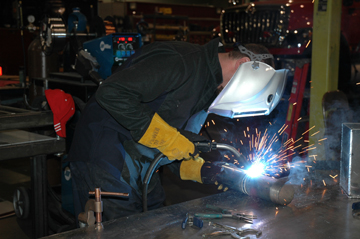
This article has been published as a web-exclusive on thefabricator.com. To read the entire story by Bernard design engineer Rob Centner, please click here.
Attacking Weld Fume at the Source
Attacking Weld Fume at the Source
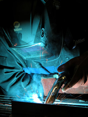
maintain compliance with safety regulations
and create a cleaner, more comfortable welding
environment. Proper use and maintenance of the
equipment is important to get optimal results.The basics
Benefits of fume extraction guns
Watch the degree of angle
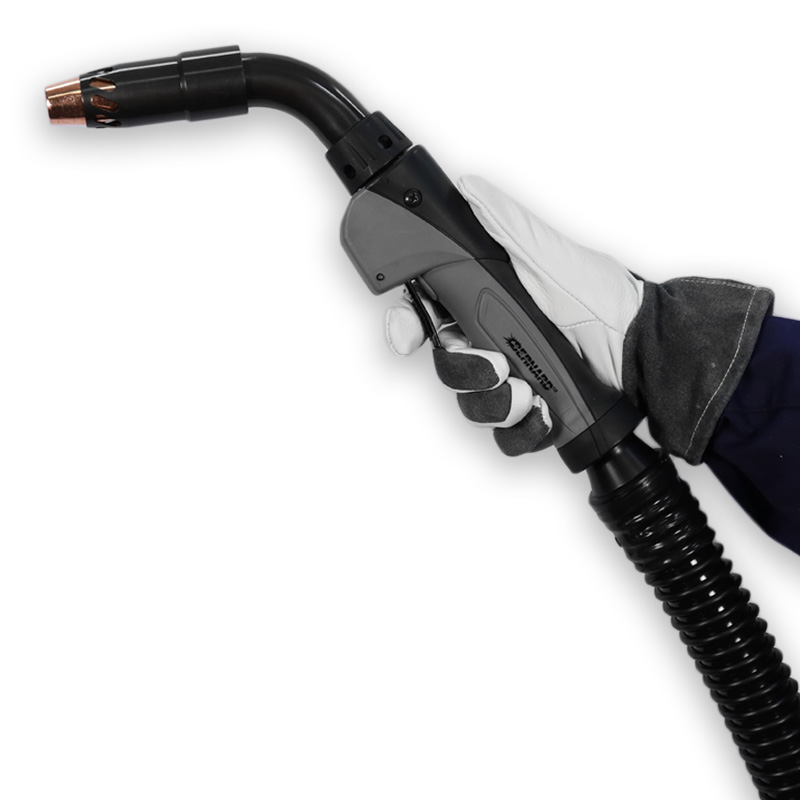
the welding process right at the source, over and around the weld
pool. As with any piece of welding equipment, fume extraction
guns benefit from preventive maintenance.Flux-cored wire allows vacuum adjustment
Pause at the end
Wire type determines stickout
Experiment with the air control regulator
Proper maintenance and consumable usage
Fume extraction guns can provide results
Preventive Robotic MIG Gun Maintenance: the Whos, Whens, Whys and Hows
Preventive Robotic MIG Gun Maintenance: the Whos, Whens, Whys and Hows
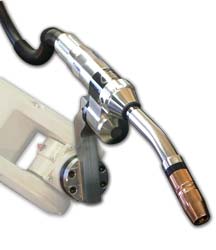
PM program basics: the whos and whens
Taking action: the whys and hows
Secure connections on a regular basis
Prevent spatter build-up
Mind the liner
Assess the welding cable and power pin
Parting thoughts on PM programs
From Technology to Technical Support: Welding in Today’s Automotive Industry
From Technology to Technical Support: Welding in Today’s Automotive Industry
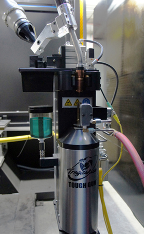
7 Ways to Save Money on Robotic Welding
7 Ways to Save Money on Robotic Welding
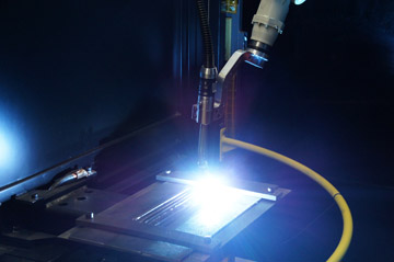
Tip No. 1: Add peripherals
Tip No. 2: Manage and maintain your consumables properly
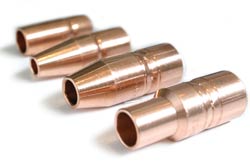
Tip No. 3: Implement a preventive maintenance program
Tip No. 4: Use the best filler metal package for the job
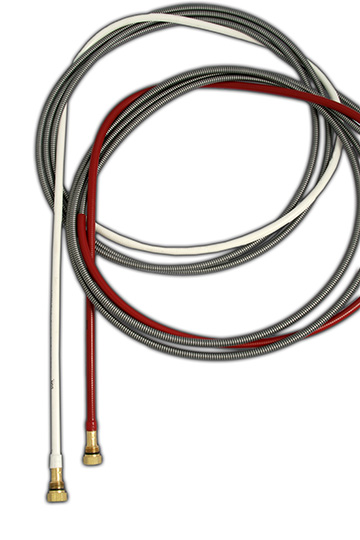
Tip No. 5: Select, trim and install the right MIG gun liner
Tip No. 6: Select the appropriate MIG gun
Having the right style and amperage MIG gun for the application can help minimize downtime for overheating and potential failure of this equipment. It can also save money by preventing the purchase of a larger (and more costly) gun than necessary for the job.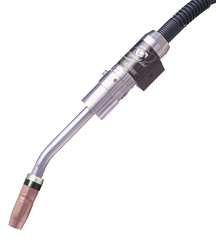
Tip No. 7: Take advantage of training opportunities
What You Should Know About Shielding Gas
What You Should Know About Shielding Gas
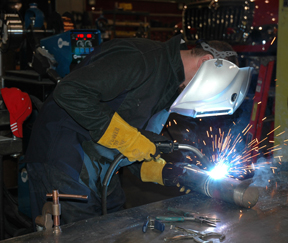
The role of shielding gases
Selecting the right shielding gas
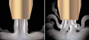
Tips for getting the most out of your shielding gas
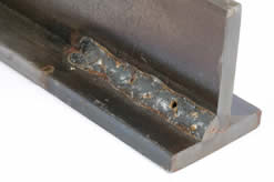
Emergency Vehicle Service Provider Gains Versatility, Comfort and More from New Welding MIG Guns
Emergency Vehicle Service Provider Gains Versatility, Comfort and More from New Welding MIG Guns

New guns offer greater versatility and comfort
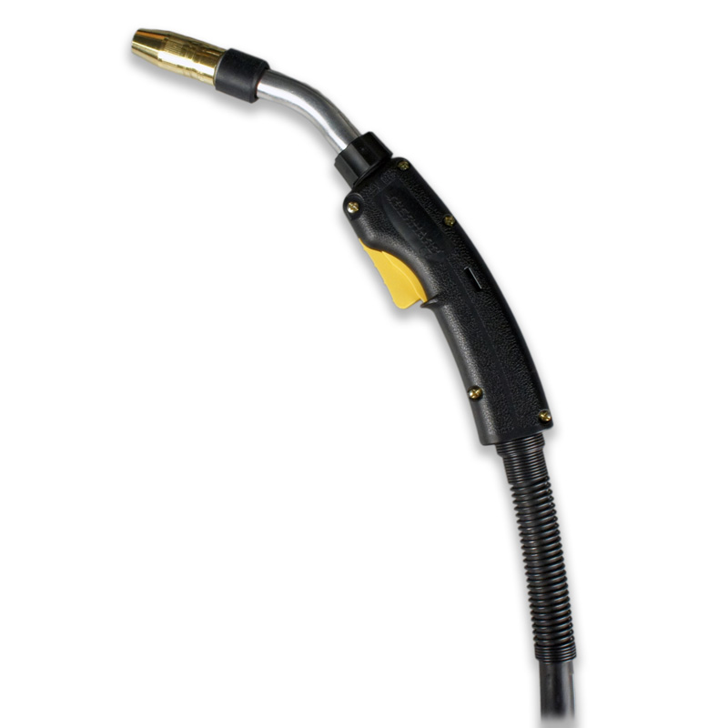
The added benefits of new consumables
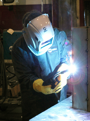
Keeping the customer happy is priority No. 1
10 Money Saving Tips for Your Semi-Automatic MIG Guns
10 Money Saving Tips for Your Semi-Automatic MIG Guns
Tip No. 1: Protect Your Assets
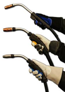
Tip No. 2: Get a Neck Up
Tip No. 3: Inspect, Clean and Tighten Regularly
Tip No. 4: Trim It Properly
Tip No. 5: Line It Up
Tip No. 6: Lighten Up
Tip No. 7: Stay Connected
Tip No. 8: Keep It Smooth and Clean
Tip No. 9: Size It Right
Tip No. 10: Think Long Term
7 Things To Know About Robotic Welding Systems
7 Things To Know About Robotic Welding Systems
1. Part repeatability is critical to successful automation
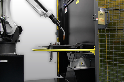
2. Training is essential
3. Additional safety equipment may be necessary
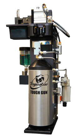
4. Weld data monitoring and/or peripherals can help improve results
Proper maintenance can help protect the investment in automation
6. Communication is key to proper weld quality and cost savings
7. Robots can do more than just weld
Preventive Maintenance Isn’t Just for Welding Robots
Preventive Maintenance Isn’t Just for Welding Robots
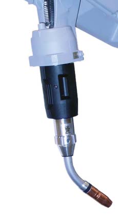
The Tasks
The Frequency and Scope
Jolson Welding
Heavy Structural Welding Simplified with Low-Speed Diesel Welder/Generators, Low-Hydrogen Flux-Cored Wire, Flux-Cored Guns and New Wire Feeding Technology
The System:
Advantages of Self-Shielded Flux-Cored Welding
Building a Welding System: The Power Source
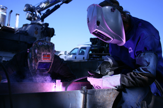
Wire Standardization Drives Quality, Productivity
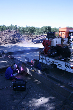
New Feeder Technology Improves Feeding Consistency
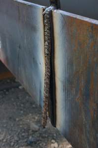
Setting Parameters Simplified Through Digital Meters, Wireless Remotes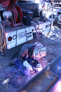
Specialized Flux-Cored Guns Take the Heat, Provide Optimal Comfort
robust design for working in hot and dusty outdoor applications.Fume Extraction Guns: Understanding the Basics
Fume Extraction Guns: Understanding the Basics
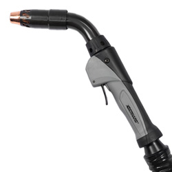
The basics of fume extraction guns
Applications, advantages and limitations
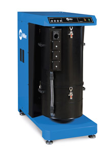
Maintenance tips
What You Must Know About Robotic Welding
What You Must Know About Robotic Welding
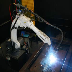
1. There’s more to the payback on a robotic welding system than just speed
2. Parts and product flow need to be consistent
3. The MIG guns and consumables on the robot can impact productivity and profitability
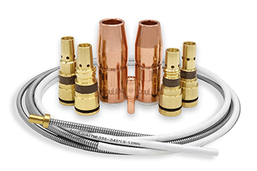
4. Peripherals can help improve the return on investment in a robotic welding operation
5. Having skilled operators with proper training to oversee the robotic weld cell is critical
The Value of Comfort: Gaining Productivity with the Right Welding Gun
The Value of Comfort: Gaining Productivity with the Right Welding Gun
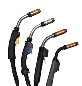
Minimize fatigue with the right handle
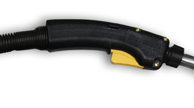
Keep power cables short, small
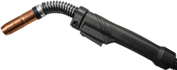
Reduce strain with the right neck
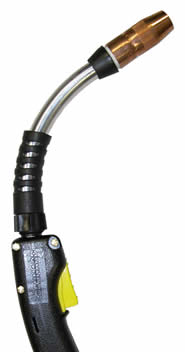
Staying comfortable by staying cool
FAQs About Robotic Peripherals Answered
FAQs About Robotic Peripherals Answered
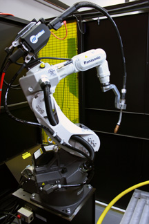
Why is a nozzle cleaning station important?
What’s the benefit of adding an anti-spatter sprayer to a nozzle cleaning station?
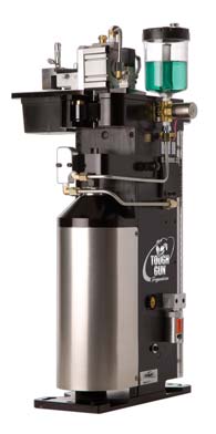
How do neck inspection fixtures work?
How can peripherals help protect against collisions?
Hybrid Robotic MIG Gun Adds to Automation Benefits for Phoenix-Based Company
TOUGH GUN I.C.E. Robotic MIG Gun Adds to Automation Benefits for Phoenix-Based Company
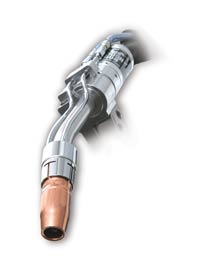
Investing in Automation
Choosing the Right Robotic MIG Gun
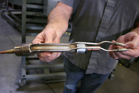
the company’s TOUGH GUN I.C.E. robotic MIG gun. The external water lines circulate coolant to the front-end consumables, helping them run cooler and last longer.Answers to Frequently Asked Questions About Welding Automation
From the Contact Tip to the Robot: Answers to Frequently Asked Questions About Welding Automation
What are the best applications for a robotic welding system?
Is it better to use fixed automation or a robot?
Who is the best candidate to operate a robotic welding system?
Can an air-cooled robotic MIG gun be used instead of a water-cooled gun?
What are the best consumables to use?
What is the benefit of touch sensing?
Is it necessary to add peripherals to a robotic welding system?
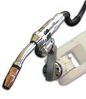
What type of payback can be expected from a robotic welding system?
Miller Welding and Machine Turns to Bernard for MIG Guns and Consumables
Partners In Growth
Miller Welding and Machine Turns to Bernard for MIG Guns and Consumables

From Humble Beginnings
Inventory Management
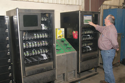
Reduced Downtime, Improved Quality
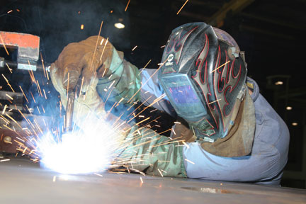
Guns that Stick
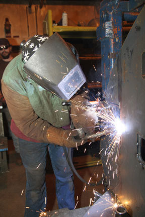
Bernard Consumables and MIG Guns Help OEM Fabricators Standardize Their Operations
Profiting In Lean Times
Bernard Consumables and MIG Guns Help OEM Fabricators Standardize Their Operations
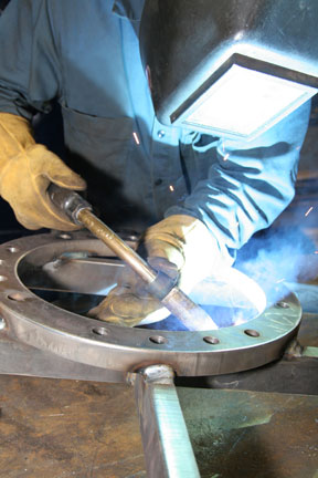
A Pro-Active Approach
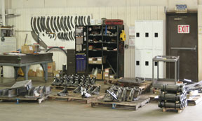
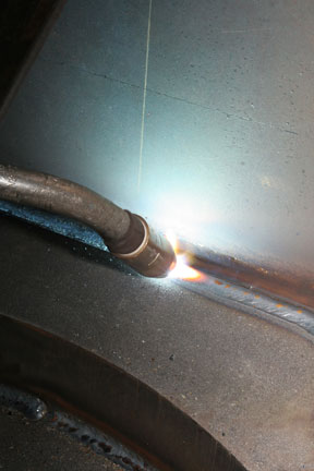
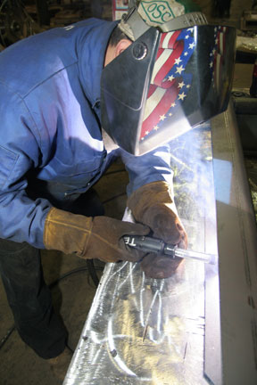
A Guide to Troubleshooting Common GMAW Gun and Conusmable Problems
Don’t Let Your Gun and Consumables Get in the Way of Your Welds
A Guide to Troubleshooting Common GMAW Gun and Consumable Problems
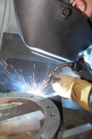
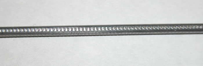
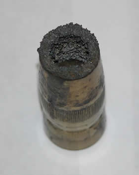
Simple Tips for Getting the Most from Your MIG Equipment
Maintain Your MIG Gun
Simple Tips for Getting the Most from your MIG Equipment
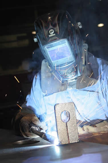
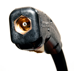
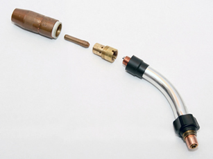
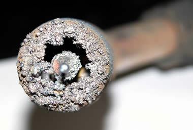
Understanding MIG Gun Liners
Understanding MIG Gun Liners
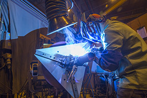
Optimizing Performance
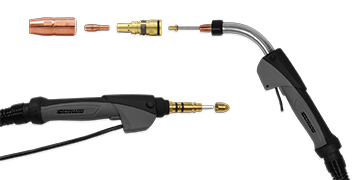
Troubleshooting
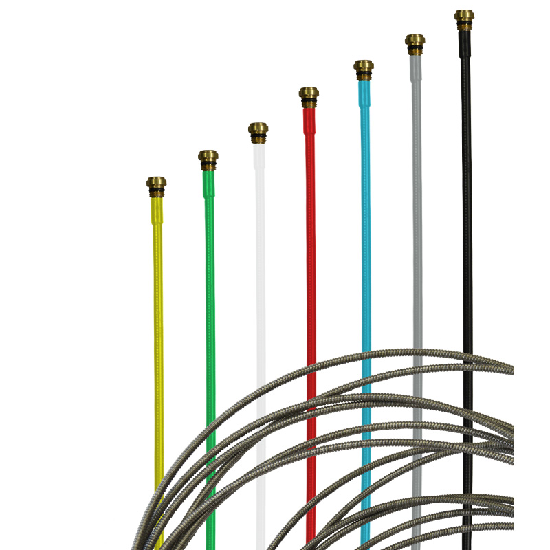
Making Your MIG Gun Consumables Last
Making Your MIG Gun Consumables Last
Simple Ways to Save Money, Improve Weld Quality and Minimize Downtime
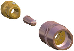
be certain that the connections between the retaining head, contact tip and nozzle are secure.
In the MIG welding process, the nozzle directs the shielding gas around the welding wire and arc to the weld puddle. Its purpose is to protect the weld from the atmosphere and/or other contaminants that can cause weld defects, such as porosity, that can lead to costly rework. Unfortunately, due to its proximity to the weld puddle, the nozzle is a common source of spatter accumulation that can obstruct that shielding gas flow.Start at the Beginning
Keep Connected
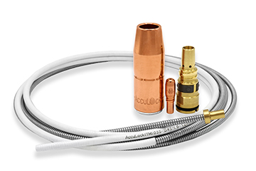
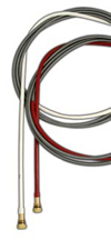
Line Up
A Final Word
![]()
![]()