Proper Storage of MIG Guns and Consumables
As with any piece of equipment in the shop or on the jobsite, proper storage and care of MIG guns and welding consumables are important. These may seem like rather insignificant components at first, but they can have a big impact on productivity, costs, weld quality and even safety.
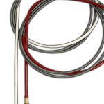
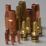
MIG guns and consumables (e.g. contact tips, nozzles, liners and gas diffusers) that are not properly stored or maintained can pick up dirt, debris and oil, which can hinder gas flow during the welding process and lead to contamination of the weld. Proper storage and care is especially important in humid environments or on jobsites near water, such as shipyards, since exposure to moisture can lead to corrosion of welding guns and consumables — particularly the MIG gun liner. Proper storage of MIG guns, cables and consumables not only helps protect the equipment from damage, but it also improves jobsite safety.
Common mistakes
Leaving MIG guns or consumables lying on the floor or the ground can lead to tripping hazards that can negatively impact worker safety. It also can cause damage to the welding cables, which could be cut or torn by workplace equipment, such as forklifts. The risk of picking up contaminants is greater if the gun is left on the ground, and can lead to poor welding performance and possibly a shorter life span.
It is not uncommon for some welding operators to place the whole MIG gun nozzle and neck into a metal tube for storage. However, this practice puts extra force on the nozzle and/or front end of the gun each time the welding operator removes it from the tube. This action can cause broken parts or nicks on the nozzle where spatter can adhere, causing poor shielding gas flow, poor weld quality and downtime for rework.
Another common storage mistake is to hang the MIG gun by its trigger. This practice will naturally change the activation point for the way the trigger level engages the switch. Over time, the MIG gun will not start in the same manner because the welding operator will have to pull the trigger progressively harder each time. Ultimately, the trigger will no longer function properly (or at all) and will require replacement.
Any of these common, but poor, storage practices can weaken the MIG gun and/or consumables, leading to poor performance that impacts productivity, quality and costs.
Tips for MIG gun storage
For proper storage of MIG guns, keep them out of the dirt; avoid hanging them in a way that could cause damage to the cable or trigger; and keep them in a safe, out-of-the-way location. Welding operators should coil the MIG gun and cable into as small of a loop as possible for storage — make sure it’s not dragging or hanging in the path of high traffic areas.
Use a gun hanger when possible for storage, and take care that the gun is hanging from near the handle and that the neck is in the air, as opposed to pointing downward. If a gun hanger is not available, coil the cable and place the MIG gun on an elevated tube, so that gun and cable is off the floor and away from debris and dirt.
Depending on the environment, welding operators may choose to coil the MIG gun and lay it flat on an elevated surface. When implementing this measure, make sure the neck is at the topmost vertical point after coiling the gun.
Also, minimize a MIG gun’s exposure to the atmosphere when it’s not being used for welding. Doing so can help keep this equipment in good working condition for longer.
Consumables storage and handling
MIG gun consumables benefit from proper storage and handling, as well. A few best practices can help to achieve a high-quality weld and maintain productivity.
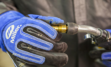
Storing consumables, unwrapped, in a bin — especially nozzles — can lead to scratching that can negatively impact performance and cause spatter to adhere more readily. Keep these and other consumables, such as liners and contact tips, in their original, sealed packaging until they are ready for use. Doing so helps protect the consumables from moisture, dirt and other debris that can damage them and minimizes the opportunity to cause poor weld quality. The longer consumables are protected from the atmosphere, the better they will perform — contact tips and nozzles that are not stored properly can wear before they are even used.
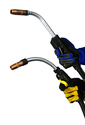
Always wear gloves when handling consumables. Oil and dirt from the welding operator’s hands can contaminate them and lead to problems in the weld.
When installing MIG gun liners, avoid uncoiling the liner and letting it drag on the floor when feeding it through the gun. When that happens, any contaminants on the floor will push through the MIG gun and have the potential to impede gas flow, shielding gas coverage and wire feeding — all factors that can lead to quality issues, downtime and potentially, cost for rework. Instead, use both hands: Hold the gun in one hand and uncoil the liner naturally with the other hand while feeding it through the gun.
Small steps for success
Proper storage of MIG guns and consumables can seem like a small issue, especially in a large shop or jobsite. However, it can have a great effect on costs, productivity and weld quality. Damaged equipment and consumables can lead to shorter product life, rework of welds and increased downtime for maintenance and replacement.
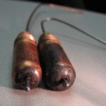
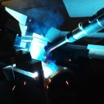
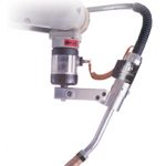
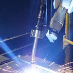
While only one part of a much larger system, the contact tip in both robotic and semi-automatic welding MIG guns plays a critical role in providing sound weld quality. It can also factor measurably into the productivity and profitability of a welding operation — downtime for excessive changeover can be detrimental to throughput, and the cost for labor and inventory. The major functions of a contact tip are to guide the welding wire and transfer the welding current to the wire as it passes through the bore. The goal is to have the wire feed through the contact tip smoothly, while maintaining maximum contact. To get the best results, it is important to have the right contact tip size —or inner diameter (ID) — for the application. The welding wire and welding process both influence the selection.
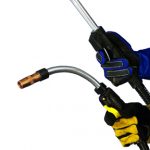
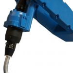
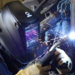
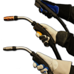
There are many considerations that factor into a company’s ability to achieve the best quality and highest productivity in the welding operation. Everything from selecting the right power source and welding process to the organization of the weld cell and workflow play a role in that success. Although a smaller part of the whole operation, MIG guns also play an important part. In addition to being responsible for delivering the current to create the arc that generates the weld, MIG guns are also the one piece of equipment that directly impacts the welding operator — day in and day out, shift after shift. The heat of the gun, along with the weight and repetitive motion of welding make it necessary to find the right gun to improve comfort and allow the welding operator the opportunity to put his or her best skills forward. With that in mind, MIG gun manufacturers throughout the industry have identified ways to make MIG guns more ergonomic and perform better. Changes that help expedite welding operator training and improve the welding environment also continue to emerge, as do MIG guns designed to reduce costs. Manufacturers continue to build features into MIG guns to help welding operators gain the highest level of quality, while also assisting them in producing a greater level of throughput. While it may seem like a minor advancement, the addition of a swivel at the base of the MIG gun handle has become an important feature that contributes positively to welding operator comfort and productivity. MIG guns that provide a 360-degree swivel offer greater maneuverability for accessing weld joints and are less fatiguing to adjust throughout the course of a welding shift. This feature also reduces the strain on the power cable, resulting in less downtime and costs for changeover. The addition of rubber handle over-molding, which is becoming more popular in industrial settings, can further improve MIG gun ergonomics by providing welding operators with a more secure and comfortable grip. The over-molding can also help reduce vibrations during the welding process, minimizing hand and wrist fatigue. MIG gun manufacturers are also adding in features to their products that help minimize costs. Among those are front-loading liners. These liners, as their name implies, load from the front of the gun (after the initial installation of the system), as opposed to conventional liners that load from the back of the gun. The benefit to front-loading liners is that they simplify installation. After the initial installation of the front-loading liner system (completed similarly to a conventional liner), the welding operator or maintenance personnel needs only to remove the nozzle and retaining head, pull out the existing front-loading liner and replace it with a new one; the gun remains attached to the feeder during this process, and wire also remains in place. As a rule, front-loading liners can cut installation time in half, minimizing costly downtime. Some manufacturers also offer a spring-loaded module that works in conjunction with a front-load liner to help minimize issues if the liner has accidentally been trimmed to an incorrect length. These modules sit in the power pin and put forward pressure on the liner after installing it from the front of the gun, providing up to 1 inch of forgiveness if the liner is too short. As companies seek out ways to address environmental regulations and create a safer, cleaner and more compliant welding operation, fume extraction guns have increased in popularity. These guns capture weld fume and visible smoke right at the source, over and around the weld pool. They operate by way of a vacuum chamber that suctions the fumes through the handle of the gun, into the gun’s hose through to a port on the filtration system. While effective in helping remove weld fume, fume extraction guns in the past have been rather heavy and bulky; they are larger than standard MIG guns in order to accommodate the vacuum chamber and the extraction hose. This extra bulk could increase welding operator fatigue and limit his or her ability to maneuver around the welding application. Manufacturers today offer fume extraction guns that are smaller (near the size of a standard MIG gun) and that feature swiveled handles to make them easier to manage. Some fume extraction guns now also feature adjustable extraction control regulators at the front of the gun handle. These allow welding operators to easily balance suction with shielding gas flow to protect against porosity. As the fabrication and manufacturing industries evolve, companies need to seek out welding equipment that can meet those changing demands — and no single MIG gun can do the job for every application. To ensure companies have the exact MIG gun necessary, many manufacturers have moved toward configurable products. MIG guns can be custom built, usually using an online configurator, according to multiple options: amperage, cable type and length, handle type (straight or curved), and neck length and angle. These configurators also offer the option to select the type of contact tip and MIG gun liners. Upon selecting the desired features for a given MIG gun, companies can purchase the unique part number through a welding distributor. Adding to the configurability of many of today’s MIG guns are accessories designed to augment their performance. Flexible necks, for example, can save labor and time by allowing the welding operator to rotate or bend the neck to the desired angle. Neck grips can add to operator comfort by reducing heat exposure and helping the welding operator maintain a steady position, leading to less fatigue and better weld quality. With the advent of advanced welding information management systems — software-driven solutions that gather weld data and can monitor most every aspect of the welding process — specialized MIG guns with a built-interface have also been introduced to the marketplace. These guns pair with the weld sequencing functions of the welding information management system, using the screen to guide the welding operator through the order and placement of each weld. Similarly, some welding performance training systems feature MIG guns with built-in displays that provide visual feedback regarding proper gun angle, travel speeds and more, allowing the welding operator to make corrections as he or she trains. Both types of guns have been designed to help streamline welding operator training and, like other MIG guns in today’s marketplace, can help support the creation of high-quality welds and positive levels of productivity in the welding operation. As companies seek out means to increase productivity and improve quality, the investment in welding automation continues to grow across the fabrication and manufacturing industries. Along with providing greater efficiencies, robotic welding systems allow companies to streamline their operations to gain cost savings and to position themselves favorably among the competition. Selecting the right robot and power source, and ensuring that the parts to be welded lend themselves to automation — namely that they are repeatable and offer joint accessibility — are all vital to success. There are also steps that companies can take to optimize the robotic welding process by way of the robotic gas metal arc welding (GMAW) gun. From making the proper selection for the application to implementing appropriate preventive maintenance and more, this component can help support greater arc-on time, reduce costs and help companies realize the benefits of welding automation. Determining the right robotic GMAW gun depends on the application, including the type and thickness of material being welded, the length of the weld and the amperage required. The type of robotic welding system also factors into the decision, as through-arm robots are becoming more prevalent in the industry and replacing many conventional robots due to their ability to reduce cable wear from routine torsion. In this case, a through-arm robotic GMAW gun, in which the cable assembly runs through the arm of the robot (as opposed to over it), is necessary. As with conventional GMAW guns, through-arm style guns are available in air- or water-cooled varieties. In most applications, air-cooled GMAW guns provide the necessary cooling capacity to protect against premature failure and offer good performance. These guns rely on both the copper in the unicable and the ambient air for cooling. In addition to working well on lower amperage applications, for welding materials up to 0.16-inch thick and for short, high-volume welds, air-cooled GMAW guns are also quite sturdy. In heavy equipment manufacturing and similar industries, water-cooled robotic GMAW guns are often chosen due to their ability to weld on thicker materials (over 1/4 inch) for longer periods of time. While more expensive up front and more to maintain, these guns offer high amperages (usually 300 to 600 amps) at 100 percent duty cycle, which makes them well suited for long weldments. These GMAW guns operate by circulating coolant from a radiator unit through the power cable via cooling hoses and through the gun and neck. This coolant returns to the radiator where it releases the heat that it absorbed during the welding process. Because of the water circuit, there is the potential for leaks so companies should take care to implement a preventive maintenance schedule to help protect against issues. In the event that a company welds materials of a variety of thicknesses at low and high amperages, a good choice for a GMAW gun is a hybrid variety featuring a durable air-cooled neck with external water lines. The neck, power cable and other components chosen for a robotic GMAW gun can have a measurable impact on welding performance and productivity. The goal with each of these items is to keep them functioning correctly and prevent premature failure so that the robot can maintain the high levels of arc-on time it was designed to provide. It is important that the robotic GMAW gun is able to access the weld joint accurately and fully, and utilizing the proper neck style and length for the job is key. Typically, GMAW gun manufacturers offer necks in multiple angles ranging from 22 to 180 degrees, and in various lengths to accommodate most robotic welding applications. In some cases, however, it may be necessary to special-order a neck. Whichever the case, having a neck that can reach the weld joint appropriately can reduce weld defects by completing the weld properly the first time, and eliminate downtime for rework. The right power cable style and length on a robotic GMAW can also help companies achieve efficiencies in the robotic welding operation. In a through-arm robotic application, the selection is simpler, as the power cable is typically sold in set lengths to match a specific make and model of robot. Still, companies may want to consider additional options for these components, such as power cables with a rotating connection. This feature helps relieve stress on the cable and power pin, resulting in less kinking and a longer life. For conventional robots, selecting the correct length of power cable is important — too long of a cable can easily kink or whip around during the welding process, whereas too short of a cable can stretch and wear more quickly. Both can result in premature cable failure, and downtime and costs for cable replacement. When in doubt about the selection, contact a trusted robotic integrator, robotic GMAW gun manufacturer or welding distributor for assistance. Companies should also look for sturdy power cables that are able to withstand UV damage from the arc and resist wear, as well as those with quick-change features to further extend cable life, simplify changeover and prevent interruptions to the welding process. Using high-quality consumables — nozzles, contact tips and gas diffusers — is another way to improve the robotic welding operation and protect the robotic GMAW gun. For higher-amperage applications, companies may want to consider a chrome zirconium contact tip to withstand the higher heat levels. The connections between consumables should always be tight to prevent electrical resistance that could lead to failure and to gain good conductivity for a smooth and stable arc. When possible, adding a nozzle cleaning station or reamer to the robotic weld cell can further optimize the performance of the consumables and the robotic GMAW gun by ensuring that the nozzle is free of spatter and able to direct the shielding gas to the weld pool to protect the weld. It can also help minimize the risk of the consumables overheating. In certain instances, companies may reprogram the robot after a collision in order to re-establish tool center point (TCP) with a bent robotic GMAW gun neck. As an alternative, a neck checking fixture (or neck inspection fixture) can adjust the neck back to the correct TCP to help improve the performance of the gun and gain greater arc-on time. The neck checking fixture tests the neck profile to ensure that the contact tip will meet the TCP. If the tool point is off because of an impact or other problem, it readjusts the neck back to the correct position. This peripheral can also be used to inspect a new robotic GMAW gun neck prior to installation to ensure it is accurate. For companies that maintain a large number of robotic welding cells, a neck checking fixture can reduce downtime and costs when exchanging necks from one robotic GMAW gun to another — welding operators need only to remove the damaged or bent neck and replace it with a spare one that has been inspected already to get the robot back to welding immediately. The damaged neck can then be set aside for adjustments while the robot is already online. For newer robots with more sophisticated collision detection software, using a solid mount to protect the gun in the event of an impact can also help maintain a more accurate TCP than a clutch mount. Unlike a clutch mount that is designed to move, these durable, high-strength mounts offer greater repeatability for higher weld quality. They are also less expensive. To help maintain accuracy, quality and speed in the robotic welding operation, additions to the robotic GMAW gun like air blast and wire brake features are beneficial. An option for both air- and water-cooled robotic GMAW guns, the air blast feature forces high-pressure air through the front of the gun to help remove debris that could enter the weld pool and negatively affect weld quality. Welding operators can program the air blast feature to operate between weld cycles to reduce unnecessary downtime. Another option for robotic GMAW guns to help optimize welding performance is the addition of a wire brake feature. As its name implies, a wire brake prevents wire feeding when welding stops. The result is a consistent wire extension at the beginning of every weld, a factor that especially complements robots using touch-sensing software — the wire brake keeps the wire in position as the robot searches for the weld joint location. This optional robotic GMAW gun feature also keeps the wire from unspooling during arc starting and stops. Preventive maintenance (PM) is critical for gaining optimal performance from a robotic GMAW gun, whether it is air- or water-cooled or a conventional or through-arm style. Recommend PM activities include: The frequency of the PM schedule will depend on the size of the robotic welding operation and the application. Companies with large weldments on thick materials stand to have greater costs and downtime for rework should the gun fail and cause a quality issue. Maintaining the robotic GMAW gun more frequently is advised.
Selecting equipment to provide the highest quality and productivity in a welding operation goes beyond just the power source or welding gun — consumables play an important role, as well. Contact tips, in particular, can make a significant difference between running an efficient process and accruing downtime to rectify problems. Selecting the right contact tip for the job can also impact the profitability of the welding operation. Contact tips are responsible for transferring the welding current to the wire as it passes through to create the arc. Optimally, the wire should feed through with minimal resistance, while still maintaining electrical contact. For that reason, it is always important to select a high-quality contact tip. While these products may cost slightly more than lesser-grade products, there is long-term value to negate that upfront purchase price. Namely, higher-quality contact tips are typically machined to tighter mechanical tolerances, creating a better thermal and electrical connection. They may also feature a smoother center bore, resulting in less friction as the wire feeds through. That means consistent wire feeding with less drag, which eliminates potential quality issues. Higher-quality contact tips can also help minimize burnbacks (the formation of a weld inside the contact tip) and help prevent an erratic arc caused by inconsistent electrical conductivity. They also tend to last longer. Contact tips used for semi-automatic MIG welding are typically composed of copper. This material provides good thermal and electrical conductivity to allow consistent current transfer to the wire, while also being durable enough to withstand the heat generated during the welding process. For robotic welding, some companies choose to use heavier-duty chrome zirconium contact tips, as these are harder than copper ones and better withstand the increased arc-on time of an automated application. In most cases, using a contact tip that matches the size of the wire leads to the best results. However, when wire is fed from a drum (e.g. those 500 pounds and larger) and/or when using solid wire, an undersized contact tip may improve welding performance. Because wire from a drum tends to have less cast, it feeds through the contact tip with less or no contact — having a smaller bore exerts more pressure on the wire, creating greater electric conductivity. Undersizing a contact tip, however, can increase friction, resulting in erratic wire feeding and, potentially, burnback. Conversely, using an oversized tip can decrease current transfer and increase tip temperatures, which can also lead to wire burnback. When in doubt about selecting the proper size contact tip, consult a trusted consumable manufacturer or welding distributor. As a best practice, always check the connection between the contact tip and the gas diffuser to be certain it is secure — a secure connection reduces electrical resistance that could lead to overheating. Contact tip recess refers to the position of the contact tip within the nozzle and is an important factor influencing weld quality, productivity and costs in a welding operation. Specifically, correct contact tip recess can reduce the opportunity for excessive spatter, porosity and burnthrough or warping on thinner materials. It can also help minimize radiant heat that could cause premature contact tip failure. Contact tip recess directly impacts wire stickout, also called electrode extension. The greater the recess, the longer the stickout is and the higher the voltage, which can make the arc slightly less stable. For that reason, the best wire stickout is generally the shortest one allowable for the application; it provides a more stable arc and better low-voltage penetration. Typical contact tip positions are 1/4-inch recess, 1/8-inch recess, flush and 1/8-inch extension. Refer to Figure 1 for recommended applications for each. Contact tip failure can result from a number of influences, including burnbacks, mechanical and electrical wear, poor welding operator technique (e.g., variations in gun angle and contact-tip-to-work-distance [CTWD]) and reflective heat from the base material, which is common in tighter access weld joints or confined areas. The quality of the wire being used can also affect contact tip life. Poor quality wire often has an undesirable cast or helix that can cause it to feed erratically. That can prevent the wire and contact tip from connecting properly through the bore, resulting in low conductivity and high electrical resistance. These issues can lead to premature contact tip failure due to overheating, as well as poor arc quality. To extend contact tip life, consider the following: In some instances, it may be desirable to convert to a water-cooled MIG gun to help keep the front-end consumables, including the contact tip, cooler and running for longer. Companies should also consider tracking their contact tip usage, noting excessive changeover and addressing accordingly with some of the suggested precautions. Addressing this downtime sooner than later can go far in helping companies reduce unnecessary costs for inventory, while also improving quality and productivity.
For some fabricators, the choice between an air-cooled or a water-cooled robotic MIG welding gun is simple. Some heavy-duty applications simply demand a water-cooled model due to the high amperage and duty cycle requirements of the job — performance requirements that would cause an air-cooled gun to quickly overheat and fail. However, there are other less conventional robotic welding applications that may benefit from using a water-cooled MIG gun, too, and can contribute to much lower consumable costs and greater productivity. Water-cooled MIG guns typically have higher duty cycles and amperages, meaning they can be run for longer periods of time without stopping. Cooler guns mean cooler front-end consumables. In particular, it is possible to greatly extend contact tip life with these guns compared to air-cooled models. Deciding which system is the best choice involves careful analysis of several factors. In addition to amperage requirements and duty cycle, a fabricator should consider the up-front costs, potential return on investment (ROI) and the application specifics. Some fabricators may choose water-cooled robotic MIG guns based on the length of welds — the long arc-on time needed to produce these welds generates more heat in the gun. Similarly, critical start and stop points along a longer weld joint typically require a gun that can handle the extended amount of welding. Considering the weld joint design and the material type and thickness, as well as joint access can also factor into whether to choose a water-cooled MIG gun. For example, aluminum or heavy plate sections that have been pre-heated can generate substantial radiant heat that affects the cooling of the gun and can adversely affect the life of the front-end consumables. A water-cooled gun can help here. Some water-cooled robotic MIG guns have smaller diameter necks than air-cooled model due to optimized cooling capacity that requires less copper in the neck. As a result, they can reach into tighter spaces, through complex tooling restraints or into parts with access holes. When deciding whether a water-cooled robotic MIG gun is the best choice, it’s important to keep in mind that these products require more maintenance and often have a higher up-front cost. It is necessary to weigh those factors against the productivity gains and savings that can result from longer consumable life. Keeping MIG welding equipment cool is necessary to protect the power cable, gun body, neck and consumables from damage due to the radiant heat from the arc and the resistive heat from the electrical components in the welding circuit. A traditional water-cooled robotic MIG gun circulates a coolant from a radiator unit through cooling hoses inside the power cable and into the gun body and neck. The coolant returns to the radiator where the radiator’s baffling system releases the heat absorbed by the coolant. There are guns available on the market today, however, that cool only the front of the gun where heat is generated and still use an air-cooled cable. These features help save costs and eliminate potential leaks from the cable bundle where excess movements from whipping and repetitive motion create the greatest wear. These features contrast to a completely air-cooled MIG welding system, which relies solely on the ambient air and shielding gas to dissipate heat that builds up along the length of the welding circuit. Air-cooled systems use much thicker copper cables, and inner neck tubes; water-cooled robotic MIG guns use much less copper in the power cables and thinner wall sections in the necks because the cooling solution carries away the resistive heat before it builds up. In general, water-cooled robotic MIG guns are beneficial for high-amperage applications and are typically available in 300 to 600 amp models. Closely related to amperage is duty cycle, which refers to the amount of time during a 10-minute cycle that the gun can operate at its rated capacity without overheating. Water-cooled robotic MIG guns can have varying duty cycle capacity depending on the manufacturer and model. The amperage requirements, the length of time the arc is actually operating, and how the system will deal with the heat of welding in a specific application are among the most important considerations when choosing a water-cooled robotic MIG gun. When choosing a water-cooled robotic MIG gun, be sure to select a product and consumables that use high quality materials that can handle high heat. Guns on the market come in two styles: conventional and through-arm versions.Through-arm robotic MIG guns carry the cable assembly through the arm of the robot. This style can offer greater protection since the arm of the robot shields the power cable from abrasive wear and minimizes cable whipping during air moves. It’s important to know if the robotic arm is a conventional or through-arm style, so the gun and associated mounting bracket can be chosen to match. Knowing the robot model is also important for proper mounting hardware and insulating of the gun from the robot wrist. As with air-cooled applications, make sure during installation that the selected water-cooled robotic MIG gun allows proper joint access. Having a neck design with the proper geometry that accesses the joint with the appropriate travel and work angles can prevent poor weld quality and/or the need to re-tool expensive fixtures, which could add downtime. To make sure the cable bundle is the correct length, it’s also critical to know where the wire feeder will be located on the robot. If a cable bundle is too short, it might stretch; if it’s too long, it could interfere with opposing structures and also fail prematurely due to excess flexing. Some water-cooled robotic MIG guns on the market have features that make them especially easy to use and to integrate into the robotic welding system. One available feature is the quarter-turn connection, which helps establish a quick and tight connection to help maintain good conductivity and prevent shielding gas leaks. Models with the quarter-turn connection feature are designed to seat the connection properly once a quarter turn is made, making it much easier and faster to change the neck. Water-cooled robotic MIG guns with this quarter-turn connection feature also offer an automatic shutoff valve, to shut off the water flow any time the neck is changed, which helps simplify routine maintenance. Consider adding a flow switch to a system with water-cooled robotic MIG gun. These switches ensure water is flowing through the system; if the system doesn’t detect the flow of water in the gun, it will shut down and give an error message. Operating a gun without water flow will very quickly cause a catastrophic failure. All of this means added downtime and costly repairs. Water-cooled robotic MIG guns do require more maintenance than air-cooled models, since the presence of the water circuit introduces more potential issues. For example, if a hose or the neck is leaking, coolant could drip into the molten weld pool, leading to porosity and costly rework. It’s a good idea to conduct preventive maintenance each day or before the start of each shift. Just as with any welding system, it’s important to inspect a water-cooled robotic MIG gun to ensure that all consumables and connections are tight and working properly. Inspect the water lines frequently to make sure they are tight and have no leaks, and replace the O-rings when necessary (e.g., when cracks or wear appears). Using an automatic reamer or nozzle cleaning station adds significant benefits to the preventive maintenance of water-cooled robotic MIG guns. A reamer eliminates the need to manually clean out the front-end consumables and can, with the addition of an automated sprayer, add anti-spatter compound to help extend consumable life further. This feature adds to the overall cost of the equipment, but helps increase uptime for production, with less manual intervention, and offers a solid return on investment in most robotic welding operations. Do not fall prey to the notion that it is cheaper to use tap water in a water-cooled gun, as it can cause algae growth or mineral build-up and eventually clogging. Instead, use deionized water or the specially treated coolant solution recommended by the manufacturer. These coolants contain special additives to lubricate internal pumps and O-rings, as well as to prevent algae growth. Choosing a water-cooled robotic MIG gun is often a necessity because of the demands of the application. A water-cooled model requires more up-front investment and more maintenance, but it can provide significantly longer consumable life and increased productivity from fewer consumable changeovers. Consider the various costs, specific application needs and accessibility to decide if a water-cooled robotic MIG gun offers a good option for a specific robotic application. Often a welding distributor, welding equipment manufacturer or robotic welding system integrator can help. Manufacturing and fabrication environments are dynamic, ever changing with the economy, customer demands, available labor and skill sets, and competitive forces, among other factors. To maintain a favorable position in the industry, it is critical for companies to continually look for ways to increase efficiencies while also improving quality and decreasing costs. For many, that means a shift toward welding automation, which has experienced its own changes in the last 10 years. During this time, robotic welding manufacturers have transitioned away from the manufacture of conventional robotic welding systems to the development of through-arm styles, in which the power cable of the robotic MIG gun runs through the arm of the robot as opposed to over top of it. These are now the prevalent robot styles in the industry and this change has had a direct impact on the design of the robotic MIG guns for the marketplace. But it is not the only trend associated with robotic MIG guns. Like any component of the welding operation, this equipment has continued to evolve to the demands of the industry and to provide solutions to improve the business of welding. Improving and simplifying cable management has been the driving force behind the shift toward through-arm robots and, therefore, the development of through-arm robotic MIG guns to accompany them. With conventional style robots and guns, the cable is prone to “whipping” during air movements, which causes undue stress on this portion of the gun, and can lead to premature wear and failure caused by the cable rubbing against the robot or tooling. It also creates additional cost and time for companies to implement cable management systems. The through-arm style robot and through-arm robotic MIG gun make it easier for companies to minimize downtime associated with cable management and reduce costs for cable replacement. It also eliminates the risk of selecting the wrong cable length, a common mistake that occurs with conventional robotic MIG guns. The through-arm robot model dictates the length of the robotic MIG gun cable, so there is no concern about it being too long (which requires extra cable management or could cause wire feeding issues) or being too short (which can cause the cable to stretch and fail prematurely) — both issues associated with conventional robotic MIG guns. There are other benefits to the shift to through-arm robots and through-arm robotic MIG guns, namely that they can accommodate for increases in welding speed that are also becoming customary in the industry. Robots are getting much faster, but with the through-arm robot there is no longer the concern of the robotic MIG gun cable getting caught on tooling during quick movements. Too, it is easier to complete offline robot programming or welding simulation and have it work with these robots because there is less concern about having to accommodate for clearance for the power cable in an application. If a robotic MIG gun fitted for a through-arm robot works in simulation, it will most likely work in the real-world application. As companies strive for greater arc-on time and higher productivity, robotic MIG gun manufacturers are helping by providing increasingly more durable power cables on this equipment and implementing features that simplify cable changeover. Some manufacturers offer a rotating power connection on the front of the cable that allows the robot to spin on its final axis as much as necessary without binding the cable. This feature helps minimize stress due to routine torsion and to extend the life of this part of the gun, as well as to increase the robot’s operating range by allowing it to rotate a full 720 degrees (360 degrees in both directions) and weld faster. Built-in quick-change features on many robotic MIG guns also expedite cable replacement, adding to the operation’s productivity, while the use of stronger cable materials help better resist wear and UV damage from the arc for longer component life. Another trend associated with robotic MIG guns is the use of solid mounts (also called solid arm mounts) as opposed to the clutch mounts that were used previously to protect the gun in the event of a collision — an occurrence commonly caused by an incorrectly position work piece or tooling that has been left out of position, among other factors. This trend is due to more sophisticated collision detection software being built into today’s robots. This software is increasingly capable of monitoring current rates and/or torque so it can quickly stop the robot when an impact occurs. Solid mounts are made from durable, high-strength aluminum alloys, and are an alternative to the clutches used with older robot models. There are two key benefits to using a solid mount for robotic MIG guns compared to a clutch: Clutches (also called shock sensors) are designed to recognize the physical impact of the robotic MIG gun on a solid surface during a collision and send an electrical signal back to the robot controller, causing the system to stop. While effective, clutches are designed to move, which can affect tool center point (TCP) after a collision. Also, since it is an electrical device, it costs more than a solid mount and is more prone to failure because of its internal components — expenses that many companies can now happily omit. As companies seek ways to become more competitive and produce higher volumes of parts, they need to maximize floor space to make room for more robots to do the job. As a result, robots and welding cells are becoming smaller and in many instances, tooling has become more complex. These changes pose greater space constraints when it comes to the robotic MIG gun. Many robotic MIG gun manufacturers have responded to this trend by creating guns that provide a more open work envelope around the mounting arm (the depth from the wrist of the robot to the tip of the robotic MIG gun) so maneuvering around tooling and gaining joint access becomes less cumbersome. There are also more options for neck lengths and angles available for robotic MIG guns, which helps companies gain access to complicated joints. Because many robotic welding applications tend toward higher amperages and longer arc-on times, it is critical for companies to have a robotic MIG gun that provides adequate amperage without overheating. The complexity and increased cost of water-cooled robotic MIG gun systems (compared to air-cooled models), however, make some companies wary of the investment for their high amperage applications. Too, if there is an issue with the coolant flow, there is the risk of the robotic MIG gun overheating and failing — an event that can be costly not just for replacement of the gun, but also potentially for rework of the part should quality problems occur. A development in recent years that addresses this concern is a hybrid robotic MIG gun. This type of gun has a durable neck like an air-cooled model and water lines that run external to the neck down to the nozzle. Should the coolant flow fail, the gun can rely on the underlying air-cooled unicable to provide enough current-carrying capacity for the job for a period of time, saving downtime and costs to address a complete robotic MIG gun failure. These guns also offer the higher amperage associated with a standard water-cooled gun, making them a good option for companies who need greater cooling capacity for an application. Because time is at a premium when it comes to robotic welding, companies are always looking for ways to extend their robotic welding cycle time — down to the second. To help maintain greater arc-on time while still protecting the robotic MIG gun and consumables from spatter build-up that could affect weld quality, adding air blast to robotic MIG guns is becoming a popular choice with some companies. This optional feature can be added to the robotic MIG gun and functions by blowing compressed air through the gun at a high pressure (approximately 100 pounds per square inch — psi) to clear debris loose in the front end while the robot is moving out of the way so the table/fixture can index. This addition can help companies reduce the number of times that the robotic MIG gun needs to be reamed out by a reamer or nozzle cleaning station, resulting in more arc-on time and greater productivity. While robotic MIG guns may seem like a small part of the whole automated system, their design and functionality can have a significant impact on the cost, productivity and quality of an application. The trends discussed here are just some of the ways that robotic MIG gun manufacturers have adjusted the designs and capacity of the products to help companies gain the best results in recent years. As with any piece of welding equipment, robotic MIG guns will need to continue evolving just like any equipment in order to meet companies’ changing needs and to meet the demands of the fabrication and manufacturing industry.
Consider some of the top things to know about robotic MIG guns as a way to get the most out of this equipment. When it comes to robotic welding, precision, repeatability and speed are essential to ensuring a successful outcome in the operation. In order to gain the best benefits, companies rely on the robot’s ability to execute the same weld, exactly the same way and as fast as possible. And while the robot itself, proper programming and oversight by a trained welding supervisor are all important components in the robotic welding operation, the robotic MIG gun also has a direct impact on quality and productivity, as well as costs.
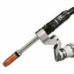
Equipment repairs are a fact of life on most jobsites, so finding ways to reduce costs and downtime while making them is important for overall efficiency and productivity — and the bottom line. The welding operation on a jobsite, just like any other portion of the business, offers opportunities to conserve resources and extend equipment life. Proper selection, handling and use of welding consumables and accessories can be helpful when it comes to getting the most out of a MIG gun, as can proper gun maintenance. Jobsites are often exposed to many environmental challenges, including extreme hot and cold temperatures, and the presence of rain and mud. It’s important to keep nozzles, gas diffusers and contact tips in the original packaging to protect against these elements until they are ready for use. Doing so also prevents scratches and/or dents from forming where spatter can accumulate and cause the consumables to fail prematurely. In addition, it prevents dirt, oil or other debris from adhering to the consumables and inadvertently entering the weld puddle, which can lead to poor weld quality. Remember, proper storage and handling doesn’t just lower actual costs for consumables by extending consumable life, it can also prevent weld defects that require costly and time-consuming rework. Choose the most appropriate neck for a MIG welding application in order to increase comfort and control, and save money. Rotatable necks, for example, can be adjusted without tools, so neck angles can be quickly changed during a welding repair once the desired position is determined. This feature is important on a jobsite where welding may be done in various positions or in tight spaces, and it helps reduce downtime for changing over MIG guns or for purchasing and inventorying extras. Rotatable necks are especially useful for welding on different angles. For hard-to-reach areas, consider a neck coupler, which allows for two existing necks to connect to extend their reach — again without the cost of purchasing a new or specialized neck. Flex necks are another good option for saving money and gaining greater comfort and control, particularly for applications with tighter joints. The operator can bend the neck to multiple angles to work around corners or get into small spaces for greater flexibility during repairs, without the expense of stocking different neck angles. Regularly perform a visual inspection of the nozzle — inside and outside — to look for spatter build-up. If there is accumulation, either clean the nozzle with a tool designed specifically for the job or replace the nozzle when necessary. During the inspection, also check that the nozzle, contact tip and retaining head are tightened properly, as these components can naturally loosen during welding. Inspecting and tightening consumables help ensure good shielding gas coverage, reliable electrical conductivity and consistent weld quality, as well as reduce costs for purchasing and replacing new consumables. It is also important to inspect the power cable on the MIG gun for any wear or damage, replacing it as necessary to avoid potential problems. Always trim MIG gun liners according to the manufacturer’s recommendations, using the proper tools and cutting the liner to the correct length. Too long of a liner can cause kinking, while cutting it too short allows debris to build up between the liner and the gas diffuser. Either way, the wrong liner length can cause poor wire feeding and premature failure of both the liner and the contact tip, adding unnecessary costs. Use a liner gauge when possible to determine the proper length for the particular liner being used. Also be certain that there are no burrs or sharp edges after the liner is cut. Also, keep the liner away from contaminants (e.g., don’t let it drag on the ground) during installation. As further protection, the welding operator’s hands or gloves should be clean when handling the liner. These precautions protect against contaminants that could enter the weld puddle and cause costly weld quality issues or downtime for rework. Use the shortest length MIG gun cable possible for the welding application, as it minimizes the opportunity for kinking, as well as premature wear of both the cable and the MIG gun liner. A shorter cable also helps prevent wire-feeding problems that could lead to an erratic arc, poor weld quality and unnecessary downtime for rework or consumable replacement. It also tends to cost less, adding to savings for repair jobs. In addition, remember to choose the correct diameter liner and contact tip for the welding wire, as this prevents similar problems and helps extend the life of these consumables. While up-front cost is an important factor when choosing consumables, consider the long-term savings offered by purchasing sturdier and more expensive consumables. These consumables likely will last longer — especially in the face of the harsh conditions of some jobsites — reducing the downtime associated with changeover and the cost of more frequent replacement of the consumables themselves. As an additional defense against spatter accumulation, purchase nozzles that have a smooth, non-porous surface. Be sure to check that the nozzles are free of any sharp edges or flat spots that would further allow spatter to adhere. Whenever possible, purchase MIG guns and consumables that are backed by a reliable manufacturer’s warranty, and use all guns and consumables as intended so as not to void the terms and conditions. Keeping these simple tips in mind can help reduce the downtime spent on maintenance and MIG gun or consumable changeover, so welding operators can get back to welding faster, get equipment back into service sooner and save money.
When it comes to welding, no two applications are alike. Just as it’s important to select a power source that is right for the job, it is also essential to select a MIG gun that will deliver the appropriate amperage and cooling capabilities. There are four main MIG gun categories to consider when making the selection: light-duty, heavy-duty, air-cooled and water-cooled. Like any welding equipment, each has its advantages and disadvantages, as well as applications for which it is best suited. Depending on the amount of arc-on time required for an application and the amperage needed, a light- or heavy-duty MIG gun may be the best choice. The key is to make sure that the gun provides the necessary amperage to avoid overheating and premature failure. As a general rule, light-duty MIG guns work well for welding on thin materials, like sheet metal, for tacking or for other applications that require short arc-on times. These guns tend to be smaller and lighter than heavy-duty guns, making them more comfortable for the welding operator, and most MIG gun manufacturers offer them in models ranging from 100 to 300 amps. Light-duty MIG guns also tend to be less expensive than heavy-duty ones and use light- or standard-duty consumables (nozzles, contact tips and gas diffusers) that are also less expensive. There are some limitations to consider when using light-duty MIG guns, too. Despite the lower purchase price, these guns may need to be replaced more frequently due to the lighter-duty components. For example, the strain relief on light-duty guns is often made from a flexible rubber component or absent all together, which can sometimes lead to kinking and cause poor wire feeding and/or shielding gas flow. Also, some unicables on light-duty MIG guns have crimped connections and may not be able to be repaired, requiring replacement of the cable or possibly the entire gun. Heavy-duty MIG guns are typically the best option for applications requiring multiple passes on thick sections of material or for long durations of welding. They are available in the marketplace in both air- and water-cooled models (discussed below) ranging from 400 to 600 amps. The necks on these guns are often longer, which creates more distance between the welding operator and the high heat from the arc, and the handles on these guns are usually larger, too. While the handle size is vital to accommodate the larger cables necessary for higher amperage output, it can make the gun more cumbersome for the welding operator to maneuver. These guns frequently also use heavy-duty front-end consumables that are capable of withstanding high amperages and longer arc-on times, but they are more expensive. Choosing between a water- or air-cooled model for high-amperage, heavier-duty applications depends on several factors, including the amperage required, cost and operator preference. As with the considerations for a light-duty gun, applications that involve welding at lower amperages for less amount of time are best suited to air-cooled MIG guns. These guns rely on the ambient air and shielding gas to dissipate the heat that builds up along the length of the welding circuit. These systems, which range from 150 to 600 amps, use much thicker copper cabling than water-cooled systems so the guns are generally larger. Water-cooled MIG guns are best suited for applications that require long, continuous welds and are typically available in a range from 300 to 600 amps. These guns operate via a water-cooled MIG welding system that pumps cooling solution from a radiator unit, usually integrated inside or near the power source. This coolant passes through hoses inside the cable bundle and into the gun handle and neck. The coolant returns to the radiator where a baffling system releases the heat absorbed by the coolant. The ambient air and shielding gas further disperses the heat from the welding arc. Each MIG gun has its advantages and disadvantages. Water-cooled MIG guns are more expensive up-front and can require more maintenance and operational costs. However, water-cooled guns also are much smaller and lighter than air-cooled guns, so they can provide productivity advantages by reducing welding operator fatigue. Also, because water-cooled guns require more equipment, they can be impractical for applications that require portability. The goal when selecting between air- or water-cooled guns, as well as light- or heavy-duty models, is to weigh out pros and cons like these and always make the selection that will provide the capacity to prevent downtime and drive productivity. Premature contact tip failure is a common problem that can lead to unexpected downtime — and added costs — in a welding operation. This issue not only hinders productivity, it can also negatively affect weld quality and create rework. Contact tips play a critical part in achieving high quality welds. Because of the constant friction from the wire and the exposure to the heat of the arc (and, in some cases, the reflective heat from the base material), contact tips take a tremendous amount of abuse during welding. This can easily turn into premature contact tip failure without the proper precautions. Understanding the typical types of contact tip failures and their causes is the best approach to preventing them. There are two main types of contact tip failure. 1. Failure that leads to a burnback and its associated problems 2. Failure that produces contact tip wear Burnbacks occur when a weld forms within the contact tip and can occur at any point along the weld. They are not necessarily the result of poor contact tip performance, but rather burnbacks can result from too slow of wire feed speeds and/or incorrect contact-tip-to-work distance (also referred to as CTWD). The CTWD is the distance between the end of the contact tip and the base material; if the distance is too short (i.e. the contact tip is too close to the workpiece), a burnback can occur. The quality of the wire, incorrect parameter settings and micro-spatter buildup, as well as incorrect wire feeder and liner adjustments can all contribute to burnbacks. When they occur, burnbacks reveal themselves by way of poor arc starts, arc instability, inconsistent wire feeding and, ultimately, stoppages in wire feeding altogether. Contact tip wear can be both mechanical and electrical. It occurs from the friction of the wire feeding through the bore of the contact tip and is especially prevalent in higher amperage semi-automatic and robotic applications. In the latter, contact tip wear can produce issues with tool center point (TCP), resulting in offset welds and potentially rework, especially in robotic welding systems that do not employ seam tracking. The design of the contact tip and the material it is composed of are two factors that affect a contact tip’s tendency toward wear. Typically, manufacturers use copper for contact tips because it is readily available and offers good electrical and thermal conductivity. Copper, however, has a relatively low resistance to wear, making it more prone to failures. For higher amperage applications, companies often turn to chrome zirconium contact tips due to their strength and their ability to resist wear by heat. All contact tips, regardless of the material used to manufacture them, will eventually fail if used or abused for a long enough periods of time and/or at a high enough temperature. They are, after all, consumables with a finite lifespan. The goal, nonetheless, is to prolong the life of the consumables in order to avoid unnecessary downtime, as well as cost for additional inventory. A good step in achieving those goals is to understand the ways to help prevent contact tip failure. Burnbacks: There is no one solution to minimize contact tip failure due to burnbacks; each situation is unique and may require a series of corrective actions. The goal is to address the associated errors or issues that are leading to the burnback in the first place. The two key solutions for minimizing burnbacks include increasing the wire feed speed and/or lengthening the distance of the MIG gun from the workpiece. The nozzle should be no further than one-half inch from the base metal. Matching a welding wire with the appropriate cast for the contact tip bore tolerance can also reduce the risk for burnbacks, as it helps improve electrical contact and reduce CTWD variability. The wire’s cast is affected by three main factors: the supply reel (spool or drum); drive roll tension; and MIG gun neck angle. A tight wire cast may allow for a looser bore tolerances and still be able to make the appropriate electrical contact with the contact tip to create a stable arc. A straighter cast may require a contact tip with a tighter bore to exert pressure on the wire and create consistent conductivity. It is important to note that with a smaller contact tip bore, there is a risk of the spatter build up, so cleanliness is key. Selecting contact tips with a smooth surface and bore can also help prevent the wire from snagging on the consumable and causing a burnback. Using a contact tip/gas diffuser design that maximizes the surface area between these consumables is another option to reduce the potential for this problem — the tight connection creates less heat and can reduce micro-spatter that could hinder the wire from feeding and becoming blocked in the contact tip bore. Additional preventive measures include: • Adjusting the drive rolls to ensure smooth wire feeding Contact tip wear: The degree of wear on a contact tip depends on multiple factors, including operating temperatures; the wire cast; and the surface condition, material properties and bore tolerances of the contact tip. Lowering operating temperatures, when feasible, is among the best defenses against contact tip wear. These lower temperatures can be achieved in a number of ways, for example, using a water-cooled MIG gun. These types of guns are especially well suited for higher amperage applications (usually between 300- and 600-amps). They do, however, introduce some additional complexities to the welding operation that companies need to consider. Namely, water-cooled guns have a weaker neck than air-cooled models, so in robotic applications specifically, they can be more prone to bending in the event of a crash. They also tend to be more expensive to maintain. When deciding whether to use a water-cooled MIG gun to help combat the excessive heat that could lead to contact tip wear, users will have to weigh out the advantages and disadvantages of this equipment in terms of costs and productivity to determine if the product is the best choice. An alternative to reduce contact tip wear via lower temperatures would be to use a thermally-effective air-cooled torch in combination with front end consumables designed to dissipate heat. Typically, high quality consumables have been designed to seat firmly together to minimize electrical resistance, thereby generating less heat and reducing the opportunity for contact tip wear and failure. Remember that cheaper isn’t always better. When it comes to purchasing consumables, it may be worth the extra cost upfront for such a design in order to minimize long-term costs and downtime associated with contact tip changeover. In any welding operation, there is no single solution to instill efficiencies — it can be a matter of technique, equipment and more. However, minimizing contact tip failure is an important way to reduce downtime and costs, while also ensuring higher weld quality. Be sure to train new welding operators as to the value of taking preventive measures to combat burnbacks and contact tip wear, emphasizing the impact of these occurrences on the overall welding operation. As with any process, education can go a long way in helping companies create a more productive and profitable business.
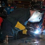
Outdoor jobsites can be harsh environments for welding equipment, including guns and consumables. When it comes to MIG or flux-cored (FCAW) welding on the jobsite, selecting the right gun for the application, and following some basic maintenance and preparation tips can help make guns and consumables last longer — factors that can help reduce costs, increase productivity and improve weld quality. Keeping this equipment up and running also helps minimize unscheduled downtime, which is key to meeting contract deadlines and keeping the business moving. This article discusses tips for protecting and maintaining MIG guns and consumables on the jobsite. Welding guns often take a lot of abuse on jobsites and in job shops, so it’s important to look for a durable gun that meets the demands of a specific application. Variables to keep in mind when selecting the gun include the material type and thickness to be welded, and how much welding will be required (if welding makes up one hour versus seven hours of each workday, for example). Additional challenges on outdoor jobsites are the weather and wind, which can blow the shielding gas away from the weld puddle, causing porosity in the completed weld. For this reason, a popular option for many outside contractors is a flux-cored welding gun, which can be used with self-shielded wire that generates its own shielding gas to reduce problems caused by wind. Whether using a MIG gun or a flux-cored gun, it’s important to select a gun with a rigid strain relief. A good strain relief (which refers to the connection between the power cable and power pin) helps minimize kinking, which can lead to poor wire feeding, an unstable arc and poor weld quality. Some additional issues to consider when selecting a gun include: • The gun should have enough amperage to meet the needs of the application. To determine the necessary amperage, consider the material type and thickness and wire size being used. • The power cable must have enough copper content to handle the amperage that will be put through it. When possible, use shorter power cables on the MIG gun to minimize costs and downtime further. As a general rule, shorter power cables are less expensive and offer better maneuverability. Shorter power cables also can help minimize wire-feeding problems associated with kinking and coiling. • The handle of the gun often is what takes the most abuse, so make sure to select a handle durable enough for the application, as some handles are designed for more light-duty applications. Choosing a handle that is comfortable for the welding operator also is important, so consider using the smallest handle that can still meet amperage needs to help minimize fatigue. • MIG gun triggers come in various styles and designs, such as standard, locking and dual schedule, and selecting the trigger often comes down to operator preference. Select a trigger that’s comfortable to use and easy to access for servicing. Some applications may be well suited for a dual-pull trigger, which allows the operator to easily switch between settings without stopping and walking back to the power source to make changes. Reducing those trips to the power source also helps improve safety by eliminating the need to navigate through cluttered jobsites and with it the potential for slips or falls. Regularly inspecting the MIG gun can be an important part of reducing costs and ensuring good welding performance, impacting productivity and efficiency. Preventive maintenance for MIG guns and flux-cored guns doesn’t have to be time-consuming or difficult. Often, the fundamental principles are the same, whether the welding is being done on a jobsite outside or in a shop. Here are some key tips for maintaining a welding gun on the jobsite: • Make sure all connections are tight. Inspect the connections between the contact tip, gas diffuser, nozzle and power pin. The wire feeder connection (where the power pin plugs into the feeder) must be tightened properly and should be free of dirt and debris. Loose or dirty wire feeder connections can cause heat to build up, leading to voltage drops that adversely affect the welding arc and may cause premature gun failure. Tighten the connection according to the manufacturer’s specification or replace the direct plug if necessary to obtain a secure fit. • Properly care for the gun liner. Make sure to install only a clean gun liner. Dragging a liner through the dirt while installing it can allow dirt and debris to accumulate on it, causing wire feeding issues. Having the proper cut length on the liner is also extremely important to help prevent birdnesting. It’s not uncommon during the course of welding for the gun liner to become clogged with debris. This accumulation of debris can, over time, lead to poor wire feeding, bird-nesting and burnbacks that require downtime to fix. Spraying compressed air through the liner can help clear out potential blockages. • Visually inspect the power cable. Look for any damage such as nicks or cuts in the power cable, which can affect wire feeding or conductivity. Power cable maintenance is an important part of eliminating unnecessary equipment costs and improving jobsite safety. Cuts in the cable can expose copper wire and lead to a potential shock hazard, while kinking obstructs gas flow and wire feeding, which can result in weld defects and arc instability. • Inspect the handle and trigger. Typically these components require little maintenance beyond visual inspection, but be sure to regularly look for cracks on the handle or missing screws. Check that the gun trigger is not sticking or otherwise malfunctioning, and replace these components as necessary. • Check the gun neck. Loose connections at either end of the neck can cause electrical resistance that leads to poor weld quality and/or consumable failures. Also, visually inspect the insulators on the neck and replace them if damaged. These insulators prevent electrically live components from exposure, ensuring operator safety and longevity of equipment. • Be mindful of consumables. Frequently inspect the nozzle and contact tip for spatter build-up, which can obstruct shielding gas flow and cause weld defects that will need to be reworked, costing time and money. Spatter build-up also can cause consumables to fail prematurely. Replace the nozzle and contact tip when necessary. • Store the gun and consumables properly. Welding equipment performs best when it’s properly stored, such as in a box or cabinet, and kept out of the elements. Liners can become corroded from exposure to the environment, which impacts the conductivity and performance of the gun. Care and maintenance can reduce costs
The cost to implement welding automation can be substantial, requiring companies to plan out the purchase carefully and to justify the expenditure to the appropriate financial or management personnel. The payback on the investment, however, can be equally beneficial. From productivity increases to quality improvements and cost savings, companies can often position themselves for greater competitiveness in the marketplace by adding robotic welding systems to their welding operation or by replacing manual welding cells altogether. Unlike companies that employ semi-automatic welding, those with robotic welding systems have the added responsibility of protecting the large capital investment in the equipment. But no two robotic welding systems are the same and likewise, there is no single step to ensure a successful outcome. Rather, a combination of the appropriate planning, equipment purchases and personnel training — among many other things — provides the best results. Paying close attention to the daily occurrences in a robotic welding cell and engaging regularly in some of the best practices discussed here can also help provide high quality results. Companies typically invest in welding automation to expedite the welding process, gain more consistent weld quality and/or to reduce costs. The process can also set companies apart from the competition by allowing for faster completion and delivery of products. For companies with high-volume demands and low-variation parts, robotic welding can become an important part of their production plans. Smaller companies with lower-volume, high-variety parts can also benefit, but they may require more flexible tooling and more programming time to accommodate for several types of products. The important consideration for both high- and low-volume production is to ensure that the parts to be welded lend themselves appropriately to an automated welding process. Robotic welding systems rely on consistent parts to provide consistent results. Companies that have or are planning to implement a robotic welding system need to be certain that parts are simple and repeatable. The presence of gaps, poor fit-up or poor joint access can have a detrimental impact on the high quality sought with robotic welding systems. Similar to a semi-automatic welding application, consistent workflow is also important for a successful robotic welding operation, with the main difference being the speed at which parts are delivered and welded since a robotic system is so much faster. The parts need to enter and leave the cell at a quicker and steadier rate — without bottlenecks — to gain optimal throughput. Companies should assess each activity leading up to the part entering the cell, making sure that the supply of parts matches the robot’s cycle time, and also assess the steps for handling the part after it leaves. In some cases, it may be necessary to change how the parts are fabricated upstream and completed downstream (e.g., finishing, painting, etc.) to establish good workflow. Companies should also look to eliminate non-value added activities, including excessive lifting or handling of parts, and avoid multiple trips to stack products or other similar activities. Robotic welding systems typically operate at higher amperages and longer duty cycles than semi-automatic welding operations — the robots can withstand the greater arc-on time and heat compared to a human operator. While those increases are excellent for supporting high productivity, the additional heat and welding duration can be especially harsh on consumables — nozzles, contact tips and gas diffusers (or retaining heads). Companies need to take steps to avoid the pitfall of excessive consumable changeover. Entering the weld cell for purposes other than part changeover or routine pauses in the operation can add unnecessarily to downtime, which can easily add up per shift, day, month and year, resulting in lost productivity. Excessive consumable changeover is also costly, as it increases inventory and inventory management. There are two key steps companies can take steps to increase consumable life in their robotic applications and reduce downtime. One, install consumables properly and maintain tight connections throughout the course of welding. Loose connections increase electrical resistance, causing the consumables to generate additional heat that can shorten their lifespan and/or cause them to perform poorly. Follow the manufacturer’s instructions for proper consumable installation, taking care to tighten the consumables appropriately. It’s also a good idea to check the consumables periodically during routine pauses in welding, as they can loosen throughout a shift. Two, install the robotic MIG gun liner properly, as this helps prevent downtime to address wire feeding issues or to correct a burnback, in which the wire “burns back” into the contact tip. Follow the manufacturer’s instructions for trimming and installation, using a liner gauge to confirm the correct liner length. Preventing premature power cable failure, which can occur in both through-arm robotic welding systems (where the cable feeds through the arm of the robot) or in standard robotic welding systems (also referred to as over-the-arm) is also important. Be mindful of the path the robot has been programmed to follow, the speed at which it moves and the cable length. The power cable should clear the robotic arm and tooling to prevent it from catching or rubbing against either part. Also, the robot should be programmed not to move too fast or abruptly. Aggressive movements can cause the power cable to snap. Make sure that the cable is the appropriate length — too short of a cable can stretch beyond its capacity during routine robotic movements, leading to greater wear. If the power cable is too long, it may be prone to kinking or becoming pinched by the robot’s arm. Preventive maintenance (PM) programs are among the most effective best practices a company can instill for a robotic welding system. Ideally, PM programs should cover every aspect of the system — from the robot to the contact tip. Proper PM activities can help prevent unscheduled downtime, low quality parts, costly repairs and/or equipment replacements. Companies will need to assess their PM needs on an individual basis and engage a maintenance team or other personnel to carry out the activities at the appropriate times and intervals. As a general rule, companies that weld thick materials or have applications with long, continuous welds common in welding automation can benefit from more frequent PM activities, as the rework for quality issues can generate much more costly rework compared to an application producing multiple smaller parts. Several PM activities can occur during routine pauses in production, including: • Cleaning the robot and fixturing to prevent the buildup of dirt, debris or anti-spatter compound, which could affect part fit-up. Other activities that happen less frequently like greasing the robots joints can be completed during a longer scheduled stop. Peripherals are often an overlooked part of the robotic welding system. The added cost of this equipment, which includes nozzle cleaning stations (also called reamers or spatter cleaners), is frequently considered an unnecessary expense. In reality, this equipment can maximize robotic welding performance and help companies gain a better return on investment (ROI) from their robotic welding system. As its name suggests, a nozzle cleaning station cleans the nozzle of dirt, debris and spatter, typically during routine pauses in the robotic welding operation. The goal of this cleaning action is to help ensure consistent shielding gas coverage, and with it, reduce weld defects, expensive rework and lost productivity. A nozzle cleaning station also helps extend the life of consumables, minimizing the downtime and expense for changeover. For the best results, the nozzle cleaning station should be mounted in close proximity to the robot to reduce the amount of time necessary for its arm to reach it. Companies can mount the peripheral overhead if need be. The robot should be programmed to clamp onto the nozzle cleaning station at a taught position exactly perpendicular to the cutting blade that clears out the spatter or other debris. Any misalignment to the position of the nozzle could lead to partial cleaning of the nozzle and excessive spatter build-up. Program the robot to go to the nozzle cleaning station as often as possible; the cleaner the consumables are, generally the better performing and longer lasting they will be. For companies who choose to attach an anti-spatter sprayer, it’s important to locate the spray in the appropriate position so it completely coats the inside of the nozzle. Ideally the outside should be covered to within three-quarters of an inch from the bottom of the nozzle. Other peripherals that companies can integrate into their robotic welding system include a wire cutter and a neck inspection tool (discussed in the next section). A wire cutter cuts the welding wire to a specified length, removing any inconsistencies at the end, providing for more reliable and smoother arc starts and better seam tracking for robots featuring that technology. For companies using touch sensing software, using a wire cutter in conjunction with a robotic MIG gun featuring a wire brake can help prevent problems with seam tracking. Touch sensing allows the robot to store position data and send electrical impulses back to the controller once it has located the joint. For applications that have slight variations in parts, touch sensing helps maintain weld consistency. It is also more cost-effective than investing in new tooling and fixturing to hold a part in a precise location; if the part moves slightly, the robot can still locate the joint and weld accurately, as long as the joint has well-defined edges. Using a wire cutter can ensure the wire is cut to a consistent length; the wire brake holds the wire in a set position as the robot articulates and searches for the weld joint, ensuring more accurate touch sensing readings for more consistent weld quality. For a robot to be repeatable and provide consistent welds, it is important for the system to maintain its tool center point or TCP, which is the focal point of the robotic MIG gun and its relationship with the position of the welding wire in the joint (gun-to-work distance). Typically, but not always, TCP issues occur after a collision, during which the neck of the robotic MIG gun becomes bent. To rectify the issue, welding operators can employ a peripheral called a neck inspection tool (or neck-checking tool) to bend the neck back to the proper angle. Most neck inspection tools are designed to accommodate standard necks for a particular brand of robotic gun. To use this peripheral, the welding operator or maintenance personnel needs to determine the tolerances for the robotic welding program and adjust the bent neck to meet the correct specifications. To maintain TCP, it is also important to install the robotic MIG gun neck properly, making sure it is fully seated. If not, it will extend too far and can cause TCP to be compromised. Programming the robot for a TCP check to verify proper position can also help prevent against quality issues and potential downtime. Another best practice to help ensure on-location welds is to check that fixturing is in the correct place, that it doesn’t allow the parts to move and that the base of the robot is securely in place. Periodically check that part variation hasn’t changed, as well. Designing parts for automation, managing workflow, selecting the right equipment and implementing a consistent PM program mean nothing if companies don’t have the right personnel in place to work with and/or oversee the robotic welding system. Investing in the people who are responsible for interacting with the robotic welding system should always be a priority. Skilled welding operators or employees with previous robotic welding experience are often a good choice for overseeing a robotic welding system. The personnel should undergo the proper up-front training before taking on the responsibility of working with the robotic welding system — loading and unloading parts and programming the robot for instance. Robotic welding integrators and robot manufacturers can often provide OEM-based training and continuing education. The goal is to instill the skills necessary not only to work with the robot on a daily basis, but also to be able to hone troubleshooting skills that can promote the maximum uptime in the robotic welding cell. These individuals can also be part of the PM programs mentioned earlier. As with any capital investment, companies need to take the appropriate steps to protect their robotic welding system. Whether it’s the addition of peripherals or implementing additional training, engaging in a few best practices can help companies gain a solid payback on the equipment, empower employees to be part of the company’s success and establish the robotic welding system as a profitable part of their business. The items discussed here are by no means exhaustive. Companies can seek out ideas for improving their operation from other, non-competitive companies, or work with a trusted welding distributor or robotic integrator for further options.
Robotic welding systems can provide many companies with increased productivity, improved quality and reduced costs — important and differentiating benefits in the fabrication and manufacturing world. However, simply implementing a robot or two isn’t enough to maximize such benefits. Organizations must understand where they should focus their resources to achieve the most gain. To help remain competitive, companies need continually to look for ways to increase throughput in their overall robotic welding process, while also keeping costs low and quality on par. But given the demographic changes taking place throughout the welding industry — many companies are seeing more turnover in management as longtime supervisors retire and new leaders join the ranks — some managers may not have as much experience with robotic welding systems. Determining how to keep the welding operation functioning in the most efficient, productive and profitable manner may become an intimidating task. This article discusses four key strategies to help welding managers, particularly those new to the job, maximize throughput in robotic welding applications. One of the first steps in improving throughput in robotic welding applications is streamlining in-house processes from beginning to end, to minimize the number of non-value-added activities. Streamlining begins with establishing a clear understanding of the entire production process as it currently functions. Issues to consider include: how long it takes to make a part; how long it takes for a part to go through the entire system; how many machines run at once; how many machines run at full capacity; floor space utilization; how often the part is handled; and proximity of components to the process areas. Gathering this kind of data is helpful in establishing baselines. Once there is an understanding of the entire process, welding managers can start looking for areas to improve. Many of the variable costs in manufacturing come from the process of actually putting products together, so reducing or eliminating non-value-added activities in this part of the process can help to reduce costs. Understanding how much time it takes for a component to move through the entire production process also can reduce the volume of inventory waiting to be processed, which saves costly space. It may also minimize some of the labor used to manage inventory, allowing it to be dedicated elsewhere in the welding operation to help improve the process. Another way to become more efficient in robotic welding processes is to seek out other manufacturers or industry experts who have had success in this area. Find another manufacturer that produces similar products (but is not a competitor) and observe their facilities and production processes. Look for these opportunities with companies known for strength in efficient fabrication or manufacturing, and ones that are gaining success in their robotic welding applications. In short, finding resources that are comparable and appropriate can help with the process of benchmarking areas for improvement. Managers also can capitalize on relationships with industry colleagues and connect with other experts via professional organizations and societies. These networking opportunities can offer good resources for industry knowledge and best practices that can then be applied within the robotic welding process. Managers may also find it useful to seek advice on best practices from the manufacturer or the integrator of the robotic welding system or products (such as robotic MIG guns, consumables or peripherals). These sources often have information to provide about integrating the products with existing equipment or investments that can be made to improve throughput. Another important step for increasing throughput in robotic welding processes is understanding what the key cost drivers are. Understanding the fixed costs and the variable costs in each step of the process enables managers to identify the key cost drivers in the complete production process. Once they have identified and measured the key cost drivers, managers can use that information to decide where to focus attention for improvement efforts to get the biggest impact. This approach can help companies become more efficient and effective operations. Some of the questions to consider when conducting a detailed analysis of cost drivers in manufacturing and fabrication include: how much it costs to produce a part; the time required to perform an activity; how much it costs for equipment maintenance; and how much it costs in lost productivity if equipment is not functioning properly. A detailed analysis of cost drivers also can help a company identify non-value-added activities, such as grinding, cleanup and part movement, and how much time is spent on those activities. This analysis is another step in deciding where improvements can be made to make the most impact on throughput. The purpose of a detailed analysis that looks at time and costs is to clarify and measure cost drivers, with the aim of developing a strategy to improve productivity. Companies can spend a lot of time and effort to measure costs and processes, and develop solutions to improve efficiencies, but may overlook the next key steps: actually following through with the improvement plans and then measuring those accomplishments. Managers may think of improving throughput as an event, when really it’s a process. Hatching good ideas and formulating solutions is important, but implementing those plans and then revisiting them for periodic review is just as important. The bottom line is managers should ask, “Are we actually doing what we said we would do, and is it working?” Implementation is most effective when it happens as a collaborative effort, rather than as a top-down mandate from management. Involve employees from the plant floor up through company management when formulating initiatives. This kind of widespread involvement and buy-in is necessary for continuous improvement and for change to successfully occur. After collaborative implementation, it’s important to follow up with an effective way to easily measure the efforts. An effective measurement strategy helps verify if the implemented processes are paying off. Following a “plan-do-check-act” model of continuous improvement can help manufacturing and fabrication facilities improve throughput in robotic welding applications.
MIG gun consumables, including the liner, can make significant difference in gun performance and weld quality. A MIG gun liner spans from the front of the gun through to the power pin and is the conduit through which the welding wire feeds. Proper installation of the liner is critical to its ability to guide the wire through the welding cable and up to the contact tip — and to help an operation avoid the many problems that can result from improper liner installation, such as birdnesting, wire feeding issues and increased debris in the liner. There are numerous liner types available that are usable for both semi-automatic and robotic applications. Choosing one is often up to the preference of the welding operator or maintenance personnel. Each type has advantages and disadvantages for specific applications in robotic and semi-automatic welding and can offer compatibility with varying gun styles and sizes. The three main categories of liner types are conventional liners, front-loading liners and front-loading liners that have a spring-loaded module to accommodate for up to 1 inch of forgiveness for improperly trimmed liners. Conventional liners are installed through the back of the gun and are longer than the cable, often up to 25 feet long. These are frequently used in the industry; so many welding operators are familiar and comfortable installing this type of liner. A disadvantage of conventional liners is the lengthy changeover process. In the cases of liner replacement, this may require the welding operator to climb over robotic tooling or transfer systems to remove the gun from the wire feeder. In the case of semi-automatic MIG guns that are connected to boom-mounted feeders, the welding operator may need to climb several feet into the air to change liners. Another disadvantage of conventional liners is that they can’t account for changes in length as the cable grows and shrinks with twisting (due to the fact that MIG gun cables are wound in a helix pattern). This can lead to the liner not being seated properly inside the retaining head. Front-loading liners are, as the name implies, installed from the front of the gun. This offers timesaving advantages, since the welding operator does not have to leave the front of the gun for changeover, which can reduce downtime. Front-loading liners have the same disadvantage as conventional liners, since they can’t grow or shrink with the cable as it twists and moves. Jump liners are a type of front-loading liner-. Whereas standard front-loading liners are full length, jump liners are shorter — often about 1 foot long — and replace only the part of the liner that wears the quickest, typically at the neck of the gun. The third main category is front-loading liners that have a spring-loaded module inserted into the power pin, allowing for up to 1 inch of motion as the cable twists and springs up and down. This type of liner tends to be more forgiving if the liner is trimmed incorrectly. Choosing the right type of liner for the application can help an operation avoid feeding issues and reduce downtime. While welders may have a preference on liner type, be aware that each type of liner has advantages and disadvantages for specific applications and can offer compatibility with varying gun styles and sizes.
MIG gun consumables are often one of the most overlooked portions of the welding operation. However, choosing the right consumables, and using and maintaining them properly can make a significant difference in gun performance and weld quality. Consumables comprise the front-end part of the gun and include the nozzle, retaining head, contact tip and liner. A MIG gun liner spans from the front of the gun through to the power pin and is the conduit through which the welding wire feeds. Proper installation of the liner is critical to its ability to guide the wire through the welding cable and up to the contact tip. Improper liner installation — which includes trimming the liner too short or having a liner that is too long — can lead to a number of problems, such as birdnesting, wire feeding issues and increased debris in the liner. These issues can result in costly rework and operator downtime for maintenance and repairs, which impacts productivity. Also, wasted wire due to issues like birdnesting can drive up costs for a company. There are several liner types available for semi-automatic applications. Choosing one is often up to the preference of the welding operator or maintenance personnel. Each type has advantages and disadvantages for specific applications and can offer compatibility with varying gun styles and sizes. Conventional liners are installed through the back of the gun and are longer than the cable, often up to 25 feet long. These are frequently used in the industry; so many welding operators are familiar and comfortable installing this type of liner. A disadvantage of conventional liners is the lengthy changeover process. In the cases of liner replacement, this may require the welding operator to climb over robotic tooling or transfer systems to remove the gun from the wire feeder. In the case of semi-automatic MIG guns that are connected to boom-mounted feeders, the welding operator may need to climb several feet into the air to change liners. Another disadvantage of conventional liners is that they can’t account for changes in length as the cable grows and shrinks with twisting (due to the fact that MIG gun cables are wound in a helix pattern). This can lead to the liner not being seated properly inside the retaining head, resulting in wire chatter and feeding issues. Front-loading liners are, as the name implies, installed from the front of the gun. This offers timesaving advantages, since the welding operator does not have to leave the front of the gun for changeover, which can reduce downtime. Front-loading liners have the same disadvantage as conventional liners, since they can’t grow or shrink with the cable as it twists and moves. Jump liners are a type of front-loading liner. Whereas standard front-loading liners are full length, jump liners are shorter — often about 1 foot long — and replace only the part of the liner that wears the quickest, typically at the neck of the gun. Front-loading liners that have a spring-loaded module inserted into the power pin allow for up to 1 inch of motion as the cable twists and the liner moves forwards and backwards. This type of liner reduces the opportunity for gaps at the front of the gun and helps to compensate if the liner is trimmed too short. Systems like the Bernard® AccuLock™ S Consumables for semi-automatic MIG guns feature a nozzle, contact tip, diffuser and liner design that work in conjunction to provide error-proof liner installation and replacement. The AccuLock™ S Liner loads through the neck at the front of the gun, then is locked and concentrically aligned to both the contact tip and power pin. The liner is then trimmed flush with the power pin — no measuring required — and reinstalled to the wire feeder. This eliminates gaps and misalignments at the front and back of the MIG gun liner for flawless wire feeding. The installation process is somewhat similar for all three types of liners, with some variations. Here are some general steps to consider when installing a new MIG gun liner. These steps are the same for both semi-automatic and robotic MIG guns: 1. Before removing the consumables, make sure the gun is straight and the cable is flattened. This makes it easier to feed the liner all the way through. 2. Trim the wire at the front of the gun to remove the bead of molten wire that often forms after welding. 3. Remove all of the front-end consumables so the liner can be fed through the gun. 4. For a conventional liner installation, remove the power pin from the feeder at the back of the gun and cut the wire. This allows the wire and a conventional liner to be removed from the back of the gun. 5. If using a conventional liner, feed the liner through the back of the gun, threading it into the power pin. Reinsert the power pin back into the feeder, and feed a few inches of wire through the back of the power pin. That way, once all of the consumables are back on at the front of the gun, the wire is already in the gun and ready to be pulled through. (See below for variations for front-load liners and front-load liners with spring-loaded modules) 6. Because the liner is longer than the gun assembly (designed to accommodate varying gun and cable lengths), there will be a foot or so of liner sticking out the front of the gun, so it’s necessary to trim the liner to the correct length. Conventional liners and front-loading liners often come with a plastic liner gauge that has a 3/4-inch stick-out. This can be fed over the top of the liner and pressed up flush against the neck, so the liner can be trimmed to the end of the gauge. 7. Hit the trigger, to pull the wire up, and at the same time purge the gun with shielding gas. There are some variances in the installation process, depending on liner type. Here are some differences to note: • When installing a front-loading liner, unravel the liner (which comes coiled) and stick the brass end — the end that goes into the receiver at the back of the gun — over the wire and through the neck. Feed the liner through the front of the gun using short strokes, to avoid kinking the liner. The front-loading liner will click or snap into place once it hits the receiver in the power pin. Once that is complete, put the liner gauge on top of the liner and follow the standard installation steps above. • When installing a front-loading liner with the spring-loaded module, the only difference is that there is no receiver in the back of the power pin. The receiver is built into the module pin. While feeding the front-loading liner into the gun using short strokes, the liner will engage with the receiver inside of the module’s power pin. When this happens, the welding operator can feel the liner spring back toward the front of the gun. This is a good sign, because it means the liner is properly engaged. Place the liner trim gauge over the front-loading liner until it is flush against the neck. Push the liner back into the gun until it bottoms out against the spring-loaded module, then trim the liner flush to the end of the liner trim gauge. After trimming, remove the liner trim gauge and release the liner. Note that the liner will spring back and stick out of the neck by approximately 1-3/4 inch, which is normal, as installing the consumables will compress the liner into its proper position. The installation process also varies when retrofitting a gun from a conventional liner to a front-loading liner, or when completing a liner changeover, as compared to installing a new liner in a new gun. When it’s not the first time the liner is being installed, there are a few additional things to remember: • When retrofitting a gun from a conventional liner to a front-loading liner, the first installation will be from the back of the gun, since a receiver is needed on the back in order to accept the front-loading liner. • After following all of the standard steps above and removing the conventional liner and wire from the gun, install the end of the front-loading liner with the O-rings on it into the receiver and unravel the liner. Feed the front-loading liner in, just as with a conventional liner, through the back of the gun, and thread the receiver into the power pin. When installing a liner as part of the AccuLock S Consumables Series, follow the same steps as when installing other types of liners, removing the front-end consumables and old liner. Then replace the new liner through the neck, and with the gun lying straight, push the liner through until the brass liner lock bottoms in the neck. To lock and center the liner, reinstall the gas diffuser and nozzle, and place the power pin cap over the liner, torquing it to 60 in-lbs (7Nm). Then simply trim the liner flush with the power pin at the back — no need to measure the liner. The quality of the liner also can impact welding performance, productivity and operator downtime, so it’s important to buy quality liners from a trusted manufacturer. Choosing the correct size of liner for the wire being used is another way to help maximize performance. While liners may seem like a small part of the welding operation, it’s important to be mindful of the impact they can have on quality, performance and costs. Liners perform a vital function in the MIG welding process, and the proper installation and maintenance of liners can help reduce costly rework, operator downtime and wasted wire.
Welding is a tough business requiring equally tough equipment. When it comes to high amperage applications that is especially true. Applications exceeding 300 amps generate a large amount of reflective heat from the arc, making it necessary to have front-end consumables — nozzles, contact tips and gas diffusers — that can withstand the course of welding, whether it’s a semi-automatic or robotic application. Such applications are particularly common in industries such as heavy equipment manufacturing, where the material thicknesses are greater and therefore require the higher amperages to create quality welds. In some automotive applications that employ robotic welding systems, amperages can also fall into that same high level. The right consumables can help in high amperage applications in a number of ways.
The MIG welding process offers many benefits for various applications and industries, including fabrication, manufacturing and general maintenance. It’s one of the easiest welding processes to learn and offers good control on thin metals. Because MIG welding uses a spool to constantly feed a wire through a welding gun, it doesn’t require frequent stopping as with stick welding. This feature makes it an efficient process that offers faster travel speeds and productivity benefits. The versatility and speed of MIG welding also make it a good option for all-position welding on various metals, including mild and stainless steels and aluminum, in a range of thicknesses. In addition, it produces a cleaner weld that requires less cleanup than stick or flux-cored welding. Selecting the right gun for the job is important to achieving good results and realizing all of the benefits MIG welding can provide. The choice of gun can have a significant impact on productivity, downtime, weld quality and operating costs, not to mention welding operator comfort. This article discusses the options to consider in selecting the appropriate MIG gun for the job. Amperage and duty cycle rating are both important considerations, but keep in mind that when it comes to amperage, bigger isn’t always better. Selecting a larger amperage gun than necessary for an application can cost money upfront and cause operator discomfort due to the increased weight, which can result in unnecessary downtime. Welding operators are often better off selecting the smallest amperage gun possible for the application, to provide them with a lighter-weight, more flexible gun that can reduce fatigue and associated downtime. Lower amperage guns also typically cost less. Duty cycle refers to the number of minutes in a 10-minute period that a gun can be operated at its full capacity without overheating. For example, a 60 percent duty cycle means six minutes of arc-on time in a 10-minute span. Because most welding operators don’t weld 100 percent of the time, it is often possible to use a lower amperage gun for a welding procedure that calls for a higher amperage one. A lower amperage MIG gun should still be capable of operating at the necessary capacity, while also offering the benefit of being easier to maneuver. That improved maneuverability can help improve weld quality and reduce the need for rework. While a lower amperage gun is appropriate for some applications, be sure the gun offers the necessary welding capacity for the job. Overworking a light-duty MIG gun can lead to premature failure. It’s also important to consider if a facility has multiple applications that make it necessary to have a gun that can handle various amperage needs. A light-duty MIG gun is often the best choice for applications that require short arc-on times, such as tacking parts or welding sheet metal. Light-duty guns typically provide 100 to 300 amps of capacity, and they tend to be smaller and weigh less than higher duty guns. Most light-duty MIG guns have small, compact handles as well, making them more comfortable for the welding operator. Light-duty MIG guns offer standard features at a lower price but typically need to be replaced more frequently. They also often use light or standard duty consumables (nozzles, contact tips and retaining heads), which have less mass and are less expensive than their heavy-duty counterparts. The strain relief on light-duty guns is usually composed of a flexible rubber component and in some cases may be absent, causing the opportunity for kinking that may lead to poor wire feeding and gas flow. Also, some unicables on light-duty MIG guns have crimped connections and may not be able to be repaired, requiring replacement of the cable or possibly the entire gun. Welding operators should watch for these potential issues. At the other end of the spectrum, heavy-duty MIG guns are often the best choice for jobs that require long arc-on times or multiple passes on thick sections of material, including many applications found in heavy equipment manufacturing and other demanding welding jobs. These guns generally range from 400 to 600 amps and are available in air- and water-cooled models. They often have larger handles to accommodate the larger cables necessary to provide the higher amperages. The guns frequently use heavy-duty front-end consumables that are capable of withstanding high amperages and longer arc-on times. The necks often are longer as well, to put more distance between the welding operator and the high heat output from the arc. When using a heavy-duty MIG gun, choosing between a water- or air-cooled model depends largely on the application and amperage requirements, operator preference and cost considerations. Applications that involve welding sheet metal for only a few minutes every hour have little need for the benefits a water-cooled system can provide. Whereas shops with stationary equipment that repeatedly weld at 600 amps likely will need a water-cooled system to handle the heat of the application. A water-cooled MIG welding system pumps cooling solution from a radiator unit, usually integrated inside or near the power source, through hoses inside the cable bundle and into the gun handle and neck. The coolant returns to the radiator where a baffling system releases the heat absorbed by the coolant. The ambient air and shielding gas further disperses the heat from the welding arc. Water-cooled guns range from 300 to 600 amps. An air-cooled system relies on the ambient air and shielding gas to dissipate the heat that builds up along the length of the welding circuit. These systems, which range from 150 to 600 amps, use much thicker copper cabling than water-cooled systems. Each system has advantages and disadvantages. Water-cooled guns are more expensive up-front and can require more maintenance and operational costs. However, water-cooled guns also are much smaller and lighter than air-cooled guns, so they can provide productivity advantages due to reduced operator fatigue. Because water-cooled guns require more equipment, they can be impractical for applications that require portability. A MIG gun’s handle, neck and power cable design can all impact how long an operator can weld without experiencing fatigue. Handle options include straight or curved — both of which come in vented styles — and the choice often boils down to welding operator preference. A straight handle is the best choice for operators who prefer a trigger on top, since curved handles for the most part do not offer this option. With a straight handle, the neck can be rotated to place the trigger on top or on bottom. In heavy-duty applications, some welding operators drape the power cable over their shoulder, and in those cases a trigger on top is more accessible. When it comes to cable selection, smaller, shorter and lighter power cables can offer greater flexibility, making it easier to maneuver the equipment and avoid clutter in the workspace. Manufacturers offer cables ranging from 8 to 25 feet long, and shorter cables often contribute to better feedability of the wire. The longer the cable, the more chance it can get coiled around things in the weld cell or looped on the floor and possibly disrupt wire feeding. However, sometimes a longer cable is necessary if the part being welding is very large. Other options to consider are the addition of a heat shield, which protects the welding operator from the heat output of a high amperage MIG gun and allows for longer arc-on time. Adding a unicable cover can protect the power cable from a harsh environment. Just as with standard MIG welding, self-shielded flux-cored welding (FCAW-SS) can offer high productivity and quality advantages in certain fabrication applications, while also providing easier training and operation. Many of the considerations for selecting a FCAW-SS gun are similar to those for selecting a standard MIG gun. Amperage and duty cycle ratings and the application requirements remain among the most important elements to consider in selecting either type of gun. Here are some issues to keep in mind for self-shielded FCAW-SS gun selection: • Operators can choose between a fixed liner and a replaceable liner, which (as the name suggests) can be replaced if it becomes clogged or damaged. • Guns with fixed liners typically have external trigger leads, while guns with replaceable liners commonly have trigger leads internal to the power cable, which prevents catching on surrounding equipment. This can be a consideration for applications that require welding around hard corners or fixtures. • Trigger options include standard or dual-schedule to allow welding operators to increase or decrease wire feed speed at the gun with the flip of a switch. Minimizing fatigue, reducing repetitive motion and decreasing overall physical stress are key factors that contribute to a safer, more comfortable and more productive environment. Choosing a MIG gun that offers the best comfort and operates at the coolest temperature allowed by the application can help improve productivity and, ultimately, the profitability of the welding operation by increasing arc-on time.
Taking into account the heat, the repetitive motions and the sometimes cumbersome equipment, gas metal arc welding (GMAW) can sometimes take a toll on welding operators in the form of aches, fatigue, and physical and mental stress. But there are tools and accessories that promote a more comfortable environment and minimize downtime. A welding gun’s handle, neck and power cable design all can significantly impact the duration of time a welding operator can weld without experiencing fatigue or stress. This article discusses some things to consider that can help optimize comfort and productivity and, ultimately, the profitability of the welding operation by allowing for greater arc-on time. One of the easiest and most important things welding operators can do to minimize fatigue and stress on the wrists and hands is to scale back on the amperage of the welding gun when possible. A lot of welding operators automatically use a 400 amp welding gun when a 250 or 300 amp model will do just fine for the job. Typically the higher the amperage, the larger the size of the gun handle and the more it weighs. MIG gun amperages reflect the temperatures above which the handle or the cable on the gun becomes uncomfortable. Using an underrated MIG gun for a higher amperage application can cause damage. Look at the application’s duty cycle requirements and how much of the time the welding operator actually spends welding, and consider using a lower-amperage welding gun if the job allows. Duty cycle is defined by the amount of arc-on time in a 10-minute period that the equipment can be operated at maximum capacity. Some welding guns offer 100 percent duty cycle, while others are rated 60 percent or below. In some cases, MIG guns offering 100 percent duty cycle may list a 60 percent duty cycle rating, as well. Regardless of the MIG gun manufacturer lists the rating, it is unlikely that a welding operator will be operating the gun at full amperage and full duty cycle at all times. That makes it feasible to use a lower amperage model for many applications. Often, the higher amperage rating is needed only if the welding operator is running the power source continuously. In that case, it is also important to ensure that the gun is capable of running at the higher duty cycle to avoid failures. In a shop setting, another option to gain greater comfort and productivity is using a water-cooled welding gun for GMAW applications. These guns can offer several benefits in production environments requiring extremely high heat applications. Water-cooled guns are generally smaller, lighter and easier for welding operators to manage for longer periods of time in high heat. However, they do come with more maintenance considerations and a higher price tag. GMAW gun manufacturers offer multiple handle and trigger options to increase welding operator comfort. Handles typically come in curved and straight designs, one or the other of which may be more comfortable for a given welding operator to hold and control. Some processes also may be more suited to a certain handle type, depending on what the work requires. But the choice between straight handle and curved handle often comes down to welding operator preference, so experiment to determine the preferred design. Usually, a smaller handle is easier for the welding operator to maneuver and many are available in the marketplace. Some manufacturers offer vented handles, which can be beneficial in that they cool down faster after the welding operator stops welding, so they may be slightly cooler when the gun is picked up again. Locking triggers are offered on some guns and can help alleviate “trigger finger,” which can occur from repetitive grasping and gripping of the gun trigger. When running a long, continuous weld, a locking trigger eliminates the necessity to squeeze the trigger throughout the whole weld, easing hand fatigue. Welding operators also can look for triggers that don’t have as much pull pressure or pull force required to maintain the arc. Many GMAW and flux-cored arc welding (FCAW) guns are available with rotatable and flexible necks in various lengths and angles. These options allow the welding operator to select one that best suits the joint access required for an application, and they help minimize unnecessary movement. If the weld requires a long reach or access at a tight corner, having a longer neck or an angled neck can improve comfort in that welding position. Flexible necks can be easily adjusted to fit different welding angles, and rotatable necks allow welding operators to rotate the neck as needed, making them a good option for welding out of position, including overhead. Neck couplers are tools that allow welding operators to combine two necks when a longer one is needed. A longer neck also can help the welding operator stay further away from the heat of the welding arc. Many manufacturers make custom necks, as well, but these generally cost much more than a neck coupler and take time for welding gun manufacturers to develop. If a welding operator needs a more immediate and less expensive solution, the neck coupler may be the better option. Another option to improve operator comfort are smaller, tapered nozzles. These can help the welding operator reach restricted joints, though remember that spatter build-up can be an issue since the opening to the nozzle is smaller and can become more easily clogged. All of these neck and nozzle features can help minimize a welding operator straining to reach a weld joint, which reduces the opportunity for fatigue or injury. Another accessory that can help with comfort and heat issues is a neck grip, typically high-temperature silicone rubber sleeves designed to reduce heat exposure and help the welding operator hold the neck in a steady position. They also allow the welding operator to rest the neck on his or her hand or forearm, using it as a pivot point to maneuver the GMAW gun more comfortably. When selecting power cables, choose the smallest and shortest power cable possible that can still meet the needs of an application. Smaller and shorter power cables are lighter and more flexible, making it easier to maneuver these components without excess stress on the wrists or hands. They also can minimize clutter in the workspace, prevent excessive coiling and reduce tripping hazards. Less clutter and coiling also cuts down on the chance of poor wire feeding that could cause downtime and hinder productivity. Another advantage: Smaller and shorter cables tend to be less expensive. Selecting standard-weight consumables can potentially ease forearm strain if the job does not call for heavy-duty consumables, as these are heavier. If the application calls for higher amperages, however, the welding operator may have to use the latter, as heavy-duty consumables dissipate more heat to prevent consumable damage and they can increase comfort in that manner — that is, by reducing heat stress. Weld position is another way to maximize comfort on the job. Place the workpiece flat and move it into the most comfortable position whenever possible. Maintaining a clean working environment is important. In some cases, a fume extraction gun paired with the proper portable fume extraction system can be a viable option to replace wearing a powered air purifying respirator, for example, and lessen the amount of equipment the welding operator has to wear. To maintain compliance and safety, it’s always a good idea to consult an industrial hygienist to be certain that’s an appropriate step. Having equipment that is easy to operate during the welding process is a good step in achieving a comfortable, safe work environment. Lightweight welding guns with appropriate handle and neck designs for the job and for the welding operator can help achieve safe and productive results. The reduction of heat stress, wrist and neck fatigue and repetitive motions can also help decrease overall physical and mental stress for welding operators.
Choosing the proper robotic MIG gun is essential for optimizing welding automation, and it can help ensure good weld quality and reduce costs. Gun amperage, duty cycle and cooling capacity all matter. Too, proper installation and maintenance is key. The appropriate feeder placement, the right cable length and proper cable management tools can all drastically reduce downtime and costs for interrupting production for repairs. Here are three MIG gun options to consider. These guns rely on the ambient air to cool them, typically operate in the range of 300-500 amps at about 60 percent duty cycle with mixed gases. They are ideal for welding thinner materials and work best for shorter welds on high volume applications, such as in the automotive or recreation equipment industries. Advantages to air-cooled guns include durability and parts that are easier to maintain and less expensive to replace. They tend to have a more streamlined design and smaller working envelope, allowing greater access to smaller joint configurations. They also maintain accuracy well, which is good for consistent, repeatable welds. Air-cooled guns do have lower duty cycles compared to water-cooled guns, and they are not capable of welding continuously for as long. These guns offer the advantage of welding at higher amperages for prolonged periods. They generally have capacity of 300 to 600 amps, and are capable of a 60 to 100 percent duty cycle. Designed for welding on thicker materials, they are a good choice for applications in heavy equipment manufacturing or similar industries. Generally, the larger the weldment, the greater the chances it requires a water-cooled gun. The circulators or chillers used to prevent overheating in water-cooled guns do tend to add to overall cost and maintenance, and the parts can be expensive and time consuming to replace if they are damaged. Also, water-cooled cables have about one-fourth the copper found in air-cooled unicables, meaning water-cooled guns quickly fail if the water supply is interrupted. A third option is a hybrid air-cooled/water-cooled gun. This is useful for applications pushing the duty cycle limits of an air-cooled model, but that don’t require a complete water-cooled solution. These guns have a durable neck and unicable like an air-cooled model and offer the higher cooling capacity of a water-cooled front end. The hybrid guns, which can provide easier maintenance than water-cooled only, typically offer 300 to 550 amperage capacity at 60 percent duty cycle. Optimizing the performance of a robotic MIG gun can help improve weld quality and reduce downtime in the welding operation, resulting in cost savings for many companies. Two optional technologies that can assist with that performance enhancement — but that may not be well-known in the welding industry — are wire brake and air blast features. Both are available as factory-installed options or they can be retrofitted in a robotic MIG gun. The wire brake feature allows welding operators to better control the start and stop of the wire feed, which can improve quality. It can also lower costs by reducing wire usage. The air blast feature helps eliminate debris in the front part of the robotic MIG gun, reducing the chance for weld contamination, which can lead to rework. Many robotic welding systems weld continuously for two or three minutes, stop for a certain amount of time to move or change position, and then weld again for a programmed amount of time. The wire brake feature automatically stops the wire from feeding through the gun when the welding stops. This feature allows for consistent wire stickout after each stoppage in preparation for the start of the next weld. This feature also helps reduce the amount of wire used, since it prevents unspooling inside the gun with each stop and start. Additionally, the wire brake can help improve weld quality because it keeps the wire feeding at a steady rate, with a consistent stickout. For robotic applications that use touch sensing, a wire brake is an important option that supports good weld quality and productivity by helping to accurately determine the location of weld joints. Touch sensing is a software system that uses the welding wire to help locate the joint in a robotic welding application. The software allows the robot to store position data and send electrical impulses back to the controller once it has located the joint. For applications that have slight variations in parts, touch sensing helps maintain weld consistency. The wire brake holds the welding wire in a set position while the robot moves and searches for the weld joint. This action helps to ensure more readings and helps maintain consistent wire stickout. Because of the consistency and accuracy it helps provide, the wire brake feature is a good option for the most demanding robotic welding applications, including the thick-plate welding common in heavy equipment manufacturing. One thing to keep in mind when retrofitting a wire brake into a robotic MIG system is that the cable housing is slightly different than a standard cable, since it has a feature to allow for the wire brake option in the front housing. Also, when the gun has a wire brake the liner must be loaded from the back, even if it is a front-loading style of liner; there needs to be a jump liner inside the neck at the front to ensure steady feed of the wire into the liner. The lack of a small jump liner can lead to wire feeding problems and loose wire inside the cable. Another option to help maximize weld quality with air-cooled robotic MIG guns is the air blast feature, which — as the name suggests — blows high-pressure air through the front of the torch to remove debris. Air blast is exclusive to air-cooled models and cannot be used on water-cooled robotic MIG guns. This feature helps remove debris and contamination from the gun, which can potentially cause poor weld quality and eventual rework. The air blast feature is easy to install and can be programmed to operate between weld cycles. There are no extra maintenance issues to remember when using the air blast feature. The wire brake and air blast features are two options that can be used together or separately to help improve quality and performance in robotic MIG gun applications, leading to cost savings for welding operations. For assistance with these features, contact a trusted welding distributor or robotic MIG gun manufacturer.
Robotic welding systems provide speed, accuracy and repeatability in many fabrication and manufacturing applications — features that can increase productivity and consistency, and reduce rework. The opportunity for savings due to these quality and efficiency improvements is a primary reason many companies make the investment in automation. There is also an increasing shortage of skilled welders entering the workforce, which makes welding automation an appealing option. However, it takes more than just installing the system to have a profitable automated welding operation. Neglecting other important steps in the process — preventive maintenance, operator training and the use of complementary equipment called peripherals, for example — can result in a robotic welding system that is not performing as well as it should. A less efficient process can lead to more expenses via rework and downtime in the long run, since a robotic welding system is only as strong as its weakest link. This article discusses some common myths about robotic welding systems that can keep a company from fully maximizing the return on investment in this technology, and provides advice to address those misconceptions.
Whether it’s in a small fabrication shop or a large manufacturing facility, investing in a robotic welding system is no minor expense. In many cases, the welding assigned to a robotic cell could also be performed in a semi-automatic or manual welding cell. However, it’s the potential advantages of the system — greater productivity, higher quality, better consistency and more cost savings — that make the purchase of a robotic welding system such an attractive option. Obtaining those results isn’t a matter of chance. At the end of the day, the robotic system needs to be able to produce more parts at an equal or higher quality and accuracy than a human operator. It’s the job of the robotic welding supervisor to make sure that happens. To achieve success in a robotic welding application, there are several key factors a robotic welding supervisor — especially one new to the task — must consider. Specifically, he or she must be able to understand the robotic system thoroughly, establish an effective documentation and maintenance routine, and look for ways to improve performance on an ongoing basis. In many cases, that may also mean enlisting the expertise of resources both inside and outside the company. Understanding the robotic system might seem like an obvious requirement for a robotic welding supervisor. With all of the administrative and operational duties that often accompany the role, however, it can be easy to simply delegate portions of the daily operation of the robotic welding system to shop floor personnel and/or the maintenance staff instead. That tendency, unfortunately, could lead to pitfalls by distancing the robotic welding supervisor from the ins and outs of the robotic welding operation. For example, the robotic welding supervisor doesn’t necessarily need to be able to troubleshoot a circuit board malfunction or rewrite the welding program, but it’s important that this individual has a solid knowledge about these components, so if an issue arises he or she can quickly recognize that there is a problem and alert the appropriate personnel to rectify it. The robotic welding supervisor should also know how the components in a robotic welding system — the robotic GMAW (gas metal arc welding) gun, consumables and cables, to mention a few — relate to each other and the impact they have on weld quality and productivity. Again, having this knowledge makes it easier to identify a potential problem and seek out the best solution. Gaining robotic welding success depends in part on establishing a rigorous documentation, maintenance and control system. When problems arise, as they undoubtedly will, they never occur without a cause. The best way to start the troubleshooting process is to look back to the last thing that was changed in the welding process — or should have been changed, but was not. Keeping an accurate and detailed log of everyone who enters the robotic welding cell is key. There should be documentation of everything personnel cleaned, changed or replaced in the cell, including adding new contact tips or other consumables, changing drive rolls or transferring a new drum of wire into the robotic weld cell. This record can help in identifying the source of a problem and getting the system back up and running with as little downtime as possible. Without such documentation, maintenance personnel could spend hours looking for the source of the issue, when in reality, they may only need a few minutes to rectify the situation. Keeping a log of activities within the robotic welding cell will also assist the supervisor in establishing an effective predictive maintenance schedule, which is the best way to keep unexpected downtime occurrences to a minimum. An activity log can help predict when a gun cable liner will fail, for example, so that maintenance personnel can prevent unplanned downtime and quality problems by changing the liner beforehand. Keeping traffic in and out of the robotic welding cell to a minimum is also important to reducing change within the operation and keeping documentation accurate. The more people coming and going from the cell, the more difficult it becomes to monitor and record activities that could affect the performance of the robot. Getting the robotic system running at peak capacity and providing an acceptable return on investment is just the beginning of establishing an effective robotic welding operation. From there, the robotic welding supervisor should look for ways to optimize and improve the robotic welding operation on a continual basis. A robotic welding cell might be running well enough to meet its daily production demands, but finding ways to improve its performance even more can bring significant advantages to a company. For example, creating greater efficiencies within the system can free up extra capacity that could be used to produce a product from somewhere else in the shop. Also, it’s important not to settle for “good enough” in the robotic welding operations. Accepting suboptimal circumstances — for instance, that a robotic GMAW gun cable is rubbing on the robot arm and must be replaced every two months or that every two hours the operator must adjust welding parameters to accommodate consumable wear — can hinder the efficiencies sought in automation in the first place. A robotic welding supervisor should never consider these types of activities as inherent to the production process, but rather seek out ways to rectify them in the name of continuous improvement. After all, a company that continues investing in robotic welding — compared to one who simply accepts and compensates for problems — stands a greater chance of gainining higher productivity and profitability, not to mention a competitive edge. To achieve the goal of continual improvement and optimization of the robotic welding operation, the supervisor should also know the resources available to him or her, both internally and externally. Internally, everyone from the daily robot operator and the quality technician to the engineering staff and the sales team should be communicating with each other to help improve the existing robotic system. These team members can also play a vital role in helping identify the company’s future robotic welding needs. The daily robot operators — those who load and unload parts and interact with the tooling — often know the specific robot and its idiosyncrasies better than anyone on the shop floor. As a result, they are often in the best position to alert the robotic welding supervisor about potential or existing problems. They may, for instance, notice that certain joint configurations or positions tend to result in excessive spatter, resulting in unnecessary post-weld clean up. By maintaining open communication with these individuals, the robotic welding supervisor can then employ the proper resources to rectify the problem. Quality technicians can be another source of valuable information to help the robotic welding supervisor improve the performance of the operation. Quality technicians might notice that welds in a certain area of a part are regularly oversized. The supervisor can then take this information to engineering, which in turn can look for solutions to revise the weld sequence or identify different system components that could further improve productivity and cost savings for the robotic welding system. Alternatively, an external resource, such as a robotic welding integrator or equipment manufacturer, can often offer insight and expertise gleaned from working with the robotic welding operations at other manufacturers. This knowledge can help companies to not only address issues within the robotic welding system, but it can also put these individuals in a position to offer advice that will make the operation run more efficiently. In this respect, the robotic welding supervisor should take the role of a communicator. He or she will be the one who understands and gathers the information from the resources available, as well as facilitating the conversations necessary to improve and optimize the robotic welding operation. Being responsible for the bottom line success of a robotic welding operation can be a daunting task. It requires a breadth of technical and business experience as well as strong people skills. Plus, as technology continually improves and evolves, the robotic welding supervisor must keep focused on improvement and optimization. They must also maintain open communication with resources both inside and outside of the facility. For those up to the challenge, however, the potential for a robotic welding system to improve quality, productivity and a company’s ultimate success is immeasurable. When 90 percent of your business focuses on boat fabrication and repairs that require you to meet specific deadlines and codes, having the right welding equipment to manage the job isn’t just ideal, it’s essential. The welding operators and supervisors at Hike Metal Products Ltd. are no strangers to this fact. They know that the equipment they use needs to produce quality results, and it has to be easy to maintain. Downtime for weld repairs or MIG gun and consumable replacements simply isn’t an option. “We’re pretty well-known worldwide in the boat building industry for the quality of the vessels we build,” explains Frank Baptista, plant manager, Hike Metal Products. “We can relate that back to the equipment we use to make our boats.” The boats to which Baptista refers include those for the Canadian Coast Guard, the popular Maid of the Mist at Niagara Falls and police boats throughout Abu Dhabi. They have also fabricated boats for areas ranging from Florida to California and Venezuela, and recently finished an $8.5 million fireboat for the Chicago Fire Department. Hike Metal Products also tackles tough fabrication and repairs for other non-marine applications ranging from water treatment plants and oil recovery to agriculture. For the last several years, Hike Metal Products has relied on Bernard T-Gun™ Semi-Automatic Air-Cooled MIG Guns (formerly Tregaskiss TOUGH GUN™ Semi-Automatic Air-Cooled MIG Guns) and TOUGH LOCK™ Consumables to meet the quality and productivity goals on its marine applications in particular. Local welding distributor, Ron Latrielle of Praxair in Chatham, Ontario introduced the products to the company. Praxair has worked with Hike Metal Products for the last 20 years, providing their welding supervisors and operators with new solutions to help them improve their welding performance and keep their competitive edge. Also involved with Hike Metal Products and their equipment is Kevin Cole, a representative from Bernard sister company, Miller Electric Mfg. Co. Along with Latrielle, Cole introduced the company to Miller XMT® 350 Multi-Process Inverters and Suitcase RC wire feeders that they have paired with their T-Gun MIG Guns to gain greater remote access to projects. Hike Metal Products, located in Wheatley, Ontario, Canada, has been serving the boat industry since 1958, designing and fabricating ferries, research vessels and patrol boats, as well as hovercrafts and icebreakers. The commission for the recent Chicago Fire Department fireboat arose, in part, from the company’s successful completion of a similar boat for the city of Baltimore, along with the company’s industry-wide reputation for quality and punctuality. Completing such a massive project, however, was no easy task. Nor was it a leisurely one. Hike Metal Products completed the job — from the day they received the raw materials for the project until they delivered the final product — in 16 months. It’s an impressive feat when you consider the fireboat is 90 feet long and capable of pumping 14,000 gallons of water a minute. It’s among the largest boats the company has fabricated and delivered in recent years. It also has a special name: the Christopher Wheatley, named in honor of a Chicago firefighter who died in the line of duty in 2010. As with most of the company’s projects, this one required welding thick portions of mild steel (up to 3/4 inch) using flux-cored wire and relatively high amperages (up to 400 amps) — often for long periods of time. The company used 1/16-inch welding wire and completed all welds to code according to the Canadian Welding Bureau (CWB). According to Latrielle, such applications very often require a water-cooled MIG gun in order to withstand the heat; however, he was able to outfit Hike Metal Products with 400-amp air-cooled models of the T-Gun MIG Gun instead — with no problems of overheating. That’s important considering that welding operators at Hike Metal Products can weld up to 60 feet of welds in a single day. “We were really pleased that we could get away with not using a water-cooled system, which just has more parts and more things to go wrong with it,” explains Latrielle. “The air-cooled T-Gun MIG Guns have been able to handle the amperage that they are pushing and get the job done.” Baptista adds that the previous MIG guns he and his team used couldn’t boast the same durability. “Because of the heat we weld with, the triggers on our old guns just wouldn’t last. We had to change them every other week,” he says. “Now if something goes wrong with our T-Gun MIG Guns, it’s almost time to change the entire gun anyway.” In addition to their durable triggers, the T-Gun MIG Guns feature a sturdy cable strain relief on the front and back ends to prevent kinking and abrasion. This feature also helps minimize the time and cost for cable replacement. The guns have the Double-Life MIG Gun System, as well: identical connections on the front and back ends. When the front end or cable becomes worn, welding operators at Hike Metal Products can double the life of their gun by removing the trigger switch and gooseneck and flip-flopping them to the back end. The guns also feature a Lifetime Warranty on handles and switches. If either component breaks, Bernard will replace them for free. “The features on the 400-amp gun are just so durable that the guns just go and go and go,” says Baptista. “That’s good, because if you’re not fixing the gun, you’re welding, right?” Hike Metal Products Quality Manager Dave Hewstone, along with Latrielle, like too that the guns have simplified the process of searching for welding equipment and maintaining inventory. The guys (welding operators) like them and they do such a good job, I don’t have to be out there looking for another product to meet the challenges of our projects all the time. What I like is that the guns perform for my customers. They do the job. We don’t hear a lot of complaints Adding to their arsenal of welding equipment is the TOUGH LOCK Consumable System that Latrielle introduced along with the Bernard T-Gun MIG Gun. This consumable system consists of TOUGH LOCK Contact Tips and Retaining Heads with Dual Taper Technology, a second rear taper between the gooseneck and the contact tip that helps improve electrical conductivity and extend the life of the TOUGH LOCK consumables. It’s a benefit that Baptista has noticed firsthand. “With our previous consumables, we changed out our contact tips anywhere from three to four times a day,” he says. “Now, in the morning, we just get rid of the old tip and put in a new one.” These contact tips also feature a dual-lead thread design that allows the tips to be rotated 180 degrees to create a new wear position and extend the tip life even further. According to Hewstone, Hike Metal Products has enjoyed a 25 percent increase in its productivity since converting to the Bernard T-Gun MIG Gun and TOUGH LOCK Consumable System. That productivity increase has resulted from the company reducing downtime for MIG gun maintenance and consumable changeover. And, jokes Hewstone, the productivity also comes from the company’s top-secret planning and fabrication. “No, really, there are no real top secrets to our success,” Hewstone says. “Just hard work, to be honest with you.”
Selecting the Right Size Contact Tip
Selecting the Right Size Contact Tip
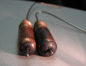
This article has been published as a web-exclusive on thefabricator.com. To read the entire story please click here.
What’s Changing? Trends in Semi-Automatic MIG Guns
What’s Changing? Trends in Semi-Automatic MIG Guns
Building in features

Reducing fume
Configuring a MIG gun
Other trends
Optimizing the Robotic Welding Process with the Right GMAW Gun
Optimizing the Robotic Welding Process with the Right GMAW Gun
Making the right choice

Choosing proper components
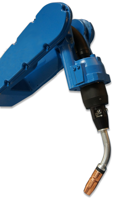
Maintaining tool center point
Adding to welding performance
Robotic GMAW gun maintenance
Tips for Choosing the Right Contact Tip
Tips for Choosing the Right Contact Tip
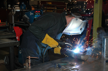
Selecting the right material and bore size
Understanding contact tip recess
Recess/Extension Amperage Wire Stick-Out Process Notes 1/4-in. Recess > 200 1/2 – 3/4in. Spray, high-current pulse Metal-cored wired, spray transfer, argon-rich mixed gas 1/8-in. Recess > 200 1/2 – 3/4in. Spray, high-current pulse Metal-cored wired, spray transfer, argon-rich mixed gas Flush < 200 1/4 – 1/2in. Short-current, low-current pulse Low argon concentrations or 100 percent CO2 1/8-in. Extension < 200 1/4 in. Short-current, low-current pulse Difficult-to-access joints Extending contact tip life
Water-Cooled Robotic MIG Guns Can Reduce Consumable Costs and Downtime
Water-Cooled Robotic MIG Guns Can Reduce Consumable Costs and Downtime
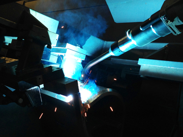
Understanding water-cooled MIG guns
Selecting a water-cooled robotic MIG gun
Maintenance and usage tips
Consider the return on investment
Trends Associated with Robotic Welding Guns
Trends Associated with Robotic Welding Guns
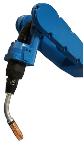
The through-arm benefits
Increased cable durability, simplified replacement
Utilizing solid mounts
Creating more space, better joint access
More cooling options
Adding the extras
More to come
5 Things to Know About Robotic MIG Guns
5 Things to Know About Robotic MIG Guns

This article has been published as a web-exclusive on thefabricator.com. To read the entire story by Tregaskiss technical support specialist, Tom Whitter, please click here.
Money-Saving Tips for MIG Guns
Money-Saving Tips for MIG Guns
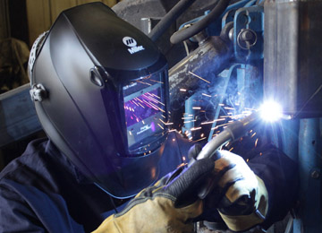
Tip No. 1: Protect the assets
Tip No. 2: Select the right neck
Tip No. 3: Perform regular inspections
Tip No. 4: Trim the liner properly
Tip No. 5: Select the best cable length for the job
Tip No. 6: Invest in consumables
Which is the Right MIG Gun? Tips for Making the Selection
Which is the Right MIG Gun? Tips for Making the Selection
Light- versus heavy-duty MIG guns
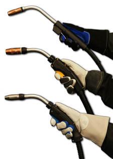
Air- versus Water-Cooled
Understanding and Extending Contact Tip Life
Understanding and Extending Contact Tip Life
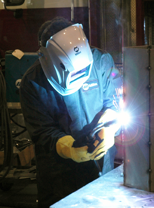
Types of contact tip failure
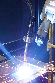
Rectifying contact tip failure
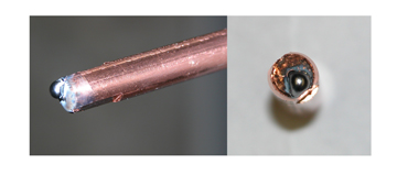
• Properly selecting and installing the MIG gun liner
• Using shorter power cables when possible
• Eliminating loops or kinks in the power cable
• Using dust covers to protect the wire from contaminants that could clog the contact tip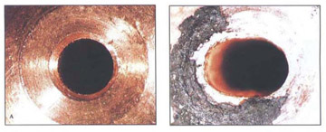
The value of extending contact tip life
Tips for Making a MIG Gun Last on the Jobsite
Tips for Making a MIG Gun Last on the Jobsite
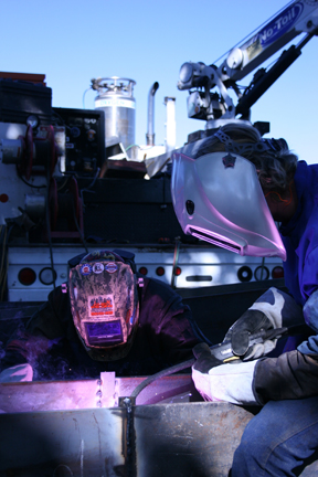
Choose a gun to fit the application
Maintaining the gun
Regular and basic care and maintenance can help extend welding equipment life on a jobsite. Simple steps such as ensuring all connections are tight and in good working order and that the weld ground is good can help produce results every day. Inspection of the MIG or flux-cored gun, equipment and consumables every time the machine is started can keep things running smoothly and reduce unplanned downtime, which helps reduce costs, extend consumable life and improve welding performance. Equipment, Training, Maintenance and More: Best Practices for Successful Robotic Welding
Equipment, Training, Maintenance and More: Best Practices for Successful Robotic Welding
Manage parts and workflow
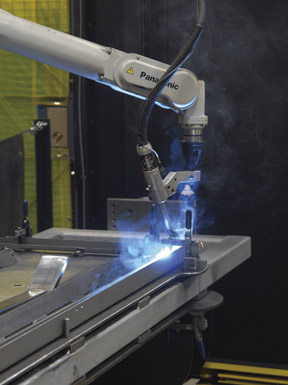
Protect against premature component failures
Don’t neglect maintenance?
• Checking for tight consumables connections.
• Confirming tool center point or TCP (discussed in more detail later).
• Checking for power cable wear and replacing as needed.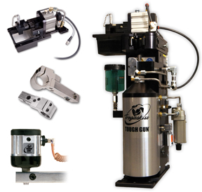
Always consider peripherals and robotic MIG gun extras
Stay on target
Find the right people
Protecting the investment
4 Strategies for Improving Throughput in Robotic Welding Applications
4 Strategies for Improving Throughput in Robotic Welding Applications
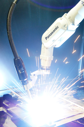
ways to increase throughput in their overall robotic welding process,
while also keeping costs low and quality on par. 1. Streamline in-house processes
2. Seek out industry experts
3. Analyze key cost drivers
4. Continue the process
How to Choose the Right MIG Gun Liner
How to Choose the Right MIG Gun Liner
Various types of liners for the job
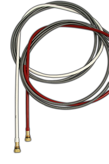
Closing thoughts
Tips for Proper Liner Installation to Help Optimize MIG Gun Performance
Tips for Proper Liner Installation to Help Optimize MIG Gun Performance
Various types of liners for the job
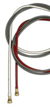
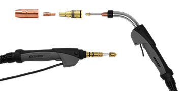
Step-by-step installation
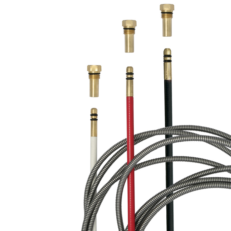
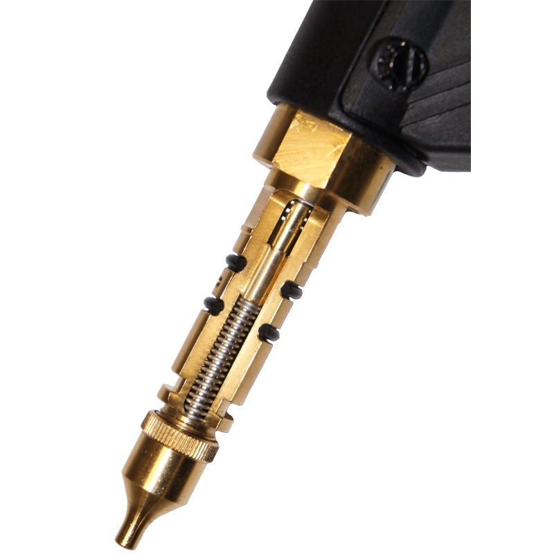
Proper liner installation can help optimize performance
Additional Resources
Consumables for High Amperage Welding: What to Know to Minimize Downtime, Costs and Quality Risks
Consumables for High Amperage Welding: What to Know to Minimize Downtime, Costs and Quality Risks
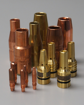
This article has been published as a web-exclusive on thefabricator.com. To read the entire article, provided by Dan Imus, Bernard and Tregaskiss account manager, please click here.
Selecting the Right Gun for MIG Welding Is Key to Achieving the Best Results
Selecting the Right Gun for MIG Welding Is Key to Achieving the Best Results
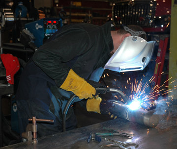
Selecting the right amperage
Choosing between light- and heavy-duty guns
Cooling options: air vs. water
Options for handles and cable selection
A side note on self-shielded flux-cored guns
The value of comfort
Gain Comfort, Productivity with the Right Welding Equipment
Gain Comfort, Productivity with the Right Welding Equipment
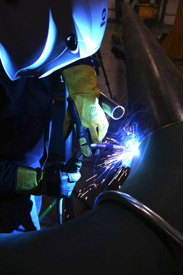
Don’t overdo the amperage
Picking the right handle
Reduce strain with the right neck
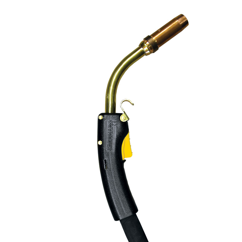
Benefits of shorter power cables
Other helpful tips
Parting thoughts
Tips for Selecting the Right Robotic MIG Gun
Tips for Selecting the Right Robotic MIG Gun
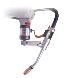
Air-cooled guns
Water-cooled guns
Hybrid air-cooled/water-cooled guns
Optional Robotic MIG Gun Features Can Improve Quality and Reduce Downtime
Optional Robotic MIG Gun Features Can Improve Quality and Reduce Downtime
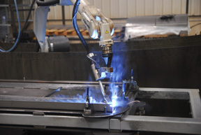
Benefits of the wire brake feature
When a wire brake offers advantages
Benefits of the air blast feature
Options that improve weld quality
5 Common Myths About Robotic Welding Systems
5 Common Myths About Robotic Welding Systems
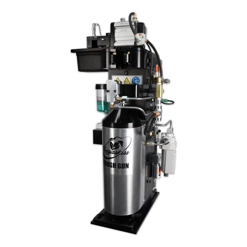
This article has been published as a web-exclusive on thefabricator.com. To read the entire story by Tregaskiss product specialist, Vic Lubieniecki, please click here.
Top Things to Teach a Robotic Welding Supervisor
Top Things to Teach a Robotic Welding Supervisor
Tip No. 1: Understand the robotic welding system
Tip No. 2: Establish documentation, maintenance and control systems
Tip No. 3: Look for continuous improvements
Tip No. 4: Rely on the available resources
Making responsible decisions that lead to growth?
Premier Boat Fabricator Improves Productivity 25 Percent with New MIG Guns and Consumables
Premier Boat Fabricator Improves Productivity 25 Percent with New MIG Guns and Consumables

Gaining greater productivity
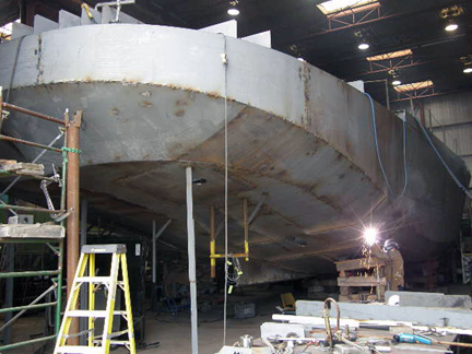
The Results
![]()
![]()