Selecting, Installing and Maintaining a Through-Arm Robotic MIG Gun
robotic MIG gun, it is important to
carefully select and maintain the gun,
and also to follow the manufacturer’s
instructions for installation.
Robotic welding systems are all about speed and repeatability. When implemented properly, they can help companies gain greater productivity and higher weld quality, while also lowering their costs and, in some cases, providing them with a competitive edge.
As with any welding equipment, robotic welding systems have undergone improvements in technology that build on those advantages. For instance, in recent years, the industry has begun to shift from conventional robots with over-the-arm robotic MIG guns to through-arm robots. These robots feature robotic MIG guns whose cable assembly, as the name suggests, runs through the arm of the robot. One significant advantage to this style of robotic MIG gun is its durability. Because the arm of the robot protects the power cable, the cable is less prone to wear from routine torsion, and it is protected from catching on fixturing or rubbing against the robot — all situations that can lead to premature failure.
Because they don’t require a mounting arm like conventional robotic MIG guns do, through-arm robotic MIG guns also provide a smaller work envelope. As a result, they are particularly well suited for applications that require access to tight spaces. The automotive industry, for example, often uses through-arm robots.
Just like any piece of welding equipment, however, through-arm robotic MIG guns require careful selection and maintenance. They also require a few precautions during the installation process.
Selection
Choosing a through-arm robotic MIG gun is much the same as choosing a conventional robotic MIG gun, with the exception of the power cable selection. These power cables are typically sold in predetermined lengths according to the make and model of the robot, as opposed to the varying cable lengths available for over-the-arm robots. Having set lengths helps minimize kinking of the cable within the arm of the robot and also helps simplify installation of the MIG gun. Always know your robot make and model when placing an order for a new gun.
When choosing a style of through-arm robotic MIG gun, look for one that offers good power cable rotation. For example, some manufacturers place a rotating power connection on the front of the cable that allows it to be rotated 360 degrees. This ability to rotate freely provides stress relief for the cable and power pin, and allows for greater maneuverability for a wider range of applications. It also helps prevent kinking that could lead to poor wire feeding, conductivity issues or premature wear or failure. Also, look for power cables constructed of durable components and materials to help prevent similar wear or failure.
It is also important to select the proper amperage of gun and be certain that it has the proper duty cycle for the given application. Most manufacturers offer guns up to 500 amps, in both air- and water-cooled models.
Finally, identify whether the robot has collision software or if the robotic MIG gun needs to be paired with a clutch to protect it in the event of a collision.
Installation
Installing a through-arm robotic MIG gun incorrectly can lead to a host of problems, not the least of which is cable failure. Incorrect installation can also cause weld quality issues, such as porosity due to poor electrical connections; premature consumable failure caused by poor conductivity and/or burnbacks; and potentially, failure of the entire robotic MIG gun.
To prevent such problems, it is imperative to consult the manufacturer’s instructions for each specific MIG gun. For through-arm robotic MIG guns, it is also important to note that the power cable needs to be installed in a slightly different manner than a conventional over-the-arm robotic MIG gun. Consider these guidelines.
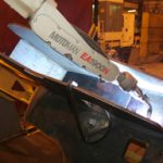
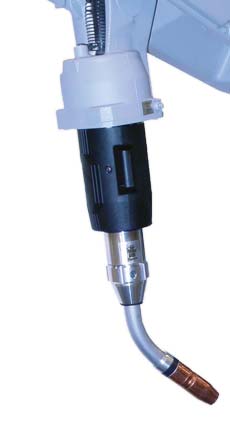
When installing a through-arm robotic MIG gun, allow approximately
1.5 inches of slack to prevent undue stress on the power cable
and power pin, and minimize the opportunity for damage
to either component.
First, position the robot with the wrist and top axis at 180 degrees, parallel to each other. Install the insulating disc and spacer the same as with a conventional over-the-arm robotic MIG gun. Be certain that the power cable position is also correct. The cable should have the proper “lie” with the robot’s top axis at 180 degrees. It’s important to avoid a very taut power cable, as it can cause undue stress on the power pin. It can also cause damage to the cable once the welding current passes through it. For that reason, it’s important to make sure the power cable has approximately 1.5 inches of slack when installing it. (See Figure 1).
Secondly, the stud on the front of the power cable needs to be fully inserted into the front connector of the through-arm robotic MIG gun. To achieve this result, always install the stud into the front housing prior to bolting the front end onto the robot wrist. By pulling the cable through the wrist and making the connections in front of the gun, it’s easy to slide the whole assembly back (once the cable is fastened) and bolt it onto the wrist. This extra step will ensure the cable is seated and will allow for maximum continuity and maximum power cable life.
Also, be certain to position the wire feeder in close enough proximity that the power cable will not be stretched unnecessarily after installation. Having a wire feeder that is too far away for the length of the power cable can cause undue stress on the cable and front end components.
Maintenance
Consistent preventive maintenance is key to the longevity of any robotic MIG gun, including the through-arm style. During routine pauses in production, check for clean, secure connections between the MIG gun neck, the diffuser or retaining heads and the contact tip. Also, check that the nozzle is secure and any seals around it are in good condition. Having tight connections from the neck through the contact tip helps ensure a solid electrical flow throughout the gun and minimizes heat build-up that could cause premature failure, poor arc stability, quality issues and/or rework.
Check regularly that the welding cable leads are secured properly and assess the condition of the welding cable on the robotic MIG gun. Look for signs of wear, including small cracks or tears, and replace as necessary.
Spatter build-up can cause excessive heat in the consumables and MIG guns, and block shielding gas flow. Visually inspect consumables and the gun on a regular basis for signs of spatter. Clean the gun as needed and replace consumables as necessary. Adding a nozzle cleaning station (also called a reamer or spatter cleaner) to the weld cell can also help. Like its name implies, a nozzle cleaning station removes spatter (and other debris) that builds up in the nozzle and diffuser. Using this equipment in conjunction with a sprayer that applies an anti-spatter compound can further protect against spatter accumulation on the consumables and the through-arm robotic MIG gun.
In addition to implementing lean practices, which many manufacturers find can greatly improve productivity and quality, some may also choose to automate their welding operations as a means to gain a competitive edge or improve profitability. This decision, however, is not one to be taken lightly. While there are many advantages to automating your welding operation, implementing a new automated welding system first requires a careful assessment of the facility, the parts to be welded and your available labor. If you are wondering whether automating is right for you, consider some of the benefits of doing so, along with the many details that you should assess before proceeding. When implemented properly, and for the right application, an automated welding system can provide marked improvements in productivity over a semi-automatic welding process — an automated welding system is significantly more efficient and can provide the throughput of several manual welding stations. That does not mean that skilled welding operators are not required in an automated welding operation. On the contrary, they are a vital part of it. Other advantages of automated welding systems include lower labor costs, as well as excellent reliability and consistency in welding performance. In many cases, an automated welding system can provide companies with an attractive return on investment (ROI) and the opportunity to lower operational costs as well. Automated welding systems rely on accuracy and repeatability to provide the quality and productivity improvements for which they have been designed. To achieve these results, the parts that you have in your welding operation need also to be consistent and repeatable. Gaps, poor fit-up or poor joint access can easily prevent an automated welding system from doing its job correctly. Simple part designs, in particular, are good candidates for an automated welding system, as they allow the robot to execute the same weld repeatedly. If you are considering an automated welding system, you should also be certain that the part does not require intricate clamping or tooling to hold it in place. It is a good idea to have a robotic integrator or welding solutions provider assess your operation and the weldments (or parts) prior to implementing an automated welding system. Generally, automated welding systems are best for high-volume, low-variety applications; however, smaller facilities can still be good candidates for automation. Often, the low-volume, high-variety applications require flexible tooling and more programming to manage several products. The additional complexity may increase the initial investment but the efficiency and productivity improvements of automation can still provide a solid return on the initial investment. It is important to assess your current operation for process flow (or workflow) to determine whether investing in an automated welding system is the right choice. In some cases, your existing operation may have to be reconfigured in advance of automation to prevent bottlenecks that could slow down the movement of parts into the automated welding cell. There are several options available, including the technique of using “U-Shaped Cells” for dedicated products, or setting up a flexible cell that can manage quick tool and fixture changes. These are particularly helpful if your welding requirements change on a daily (or hourly) basis. Automated welding systems can significantly improve quality and reduce the occurrences of weld defects. In many cases, they can also improve weld cosmetics and minimize or eliminate spatter. That being said, you should have a dependable supply of quality components that enter the automated system. Quite simply, if poor quality parts go in to the cell then poor quality parts will come out of the weld cell. Further, a consistent and reliable supply of components is required to maintain a reasonable level of Overall Equipment Effectiveness (OEE) – an important metric that evaluates the effectiveness of the manufacturing operation. Having adequate labor to supply the automated welding system with parts is also imperative. Every moment that a robot sits idle waiting for a part to weld ultimately adds up to lost productivity and increased costs. Automated welding systems require supervision and maintenance. In the process of determining whether this conversion is right for you, you should also assess your available resources and their skill set. Skilled welding operators and/or employees with prior robotic welding experience are the best candidates to supervise the weld cell. If you do not have personnel with those skill sets, be certain that you evaluate the resources (both time and fiscal) you have for training. In many cases, robotic integrators and OEMs offer training that can help provide the necessary troubleshooting and operating skills to manage an automated welding system properly. Once you assess your operation and determine that an automated welding system is a good fit, the next step is find an appropriate robotic integrator (and/or distributor) to make your vision become a reality. In addition to confirming that your parts are suitable and identifying any potential bottlenecks, these individuals can assess your facility to be certain that you have the space and services to support an automated welding system. They can also provide you with advice on updates or tooling changes that need to occur prior to implementation. Likewise, a robotic integrator can help you select the right power source, robot (aka “manipulator”), robotic controller and other key equipment. For example, the ideal power source will be one that helps maximize travel speeds, provides good arc characteristics and minimizes spatter. Additionally, a robotic integrator can discuss the benefits of adding robotic peripherals, such as nozzle cleaning stations, wire cutters and anti-spatter sprayers that focus on extending the life of your welding gun and consumables. Ultimately, the goal when deciding whether to automate your welding operation is to have a thoroughly defined plan before you start. By carefully assessing each aspect of your current welding operation and working with a trusted partner, you should be able to garner all the information you need to make an informed decision and achieve your vision for a more efficient and profitable operation.
When you invest in automation, the goal is to gain productivity and quality improvements that set your welding operation apart from the competition and help increase your bottom line. To achieve success with an automated welding system, however, you need to ensure that the parts you are welding are consistent and repeatable, confirm that your welding operation has good workflow and have properly trained welding operators to oversee the system. You also need the right equipment for the job. In addition to working with a reliable robotic integrator to select and implement the robot, you should also take care to select the right robotic MIG gun and consumables — contact tips, nozzles, liners and retaining heads — for the application. The consumables, in particular, are an easily overlooked part of an automated welding system, but they can have a measurable impact on downtime and day-to-day costs. Consider these suggestions for getting the best performance from these components. The contact-tip-to-nozzle relationship for an automated welding system varies according to the application, but it still has an impact on the welding performance and quality you achieve. Applications that have complex joints or tooling often require an extended contact-tip-to-nozzle relationship. This relationship provides greater access into more complex joints and can help you better accommodate for complex tooling. You should be mindful that this relationship also makes your contact tip more prone to spatter accumulation and may reduce the tip life due to it being more exposed to the heat of the arc. The application of an anti-spatter compound can offer some protection against such situations, but you will also need to monitor your contact tips regularly for signs of wear. Remember, preventive maintenance is better than downtime for resolving problems. Change over your contact tips before issues occur. Using heavy duty copper contact tips is a good option for reliable performance in many welding applications. Contact tips with a hardened insert are ideal for operations employing pulsed welding, as they resist wear from the harsh waveforms, and last 10 times longer than copper or chrome zirconium tips. Checking your contact tips, retaining heads (or diffusers) and nozzles for good connections can also have a measurable impact on your welding performance. Solid connections help ensure reliable electrical conductivity and minimize heat, which in turn provides more consistent weld quality and helps your consumables last longer. Look for contact tips with a long tail and coarse threads, as these help prevent cross-threading and downtime for troubleshooting associated issues like poor penetration. This design aligns the contact tip tail concentrically within the diffuser before the threads engage, making the contact tips easier for less experienced welders to install correctly. These same style contact tips also include greater mass at the front of the tip and bury the tip further in the diffuser than other styles. Such features help the contact tip last longer by resisting wear from the heat of the arc. Longer lasting contact tips mean less downtime for changeover and less risk of installation errors. Also, consumables with tapered mating surfaces provide good electrical conductivity to extend the life of the products. The welding wires you use can impact the performance of your contact tips and it can also affect what size you should use. Larger drums of wires — 500 to 1,000 pounds — are commonly used for automated welding systems to minimize changeover; however, the wire in these drums tends to have less of a cast and/or helix than wire that feeds off of a smaller spool. As a result, the wire often feeds through the contact tip relatively straight, making little or no contact with it. The effect is twofold: one, it minimizes the electrical conductivity necessary to create a good arc and a sound weld; and two, it can cause the welding wire to contact the part being welded and arc back into the contact tip, thereby creating a burnback. This condition automatically creates downtime to change over the contact tip. As a solution, consider undersizing your contact tips particularly if you are using a solid wire. For example, a .040-inch (1 mm) diameter contact tip could work for a .045-inch wire. Check with a trusted robotic integrator or welding distributor if you are using metal-cored wires, as undersizing them is not always feasible due to their tubular construction. You should also consider the impact that the wire you are using has on the longevity of your contact tip. For example, non-copper-coated solid wires tend to wear contact tips (and liners) more quickly than copper-coated ones. The copper on a copper-coated wire acts like a lubricant to improve feedability and can often extend consumable life. It may be worthwhile to factor in the higher up-front cost of these wires compared to the increased cost of purchasing more contact tips for use with a non-copper-coated wire, as well as the downtime for changeover. Automated welding systems require consumables that are capable of withstanding longer periods of welding — and most often higher amperages — than a semi-automatic application. The specific mode of transfer for (GMAW) or (MIG) welding you use can also impact the type of consumables you require. For example, pulsed welding programs in which the power source “pulses” between low background currents and high peaks, are especially harsh on consumables due to the higher levels of heat that the process generates. They tend to cause the contact tip to erode more quickly and therefore require more frequent changeover. You should carefully monitor your contact tip usage if using such a welding program so that you can determine how often the contact tips need to be replaced. Changing over these consumables before they experience problems can help prevent issues like loss of electrical conductivity, burnbacks or excessive spatter accumulation, the latter of which tends to occur when the contact tip becomes too hot and the consumable material softens. Use the time during routine pauses in production for contact tip changeover to avoid interrupting arc-on time. Typically, the tooling on your automated welding system dictates the type of nozzle that you will need to use. Bottleneck, straight or tapered nozzles are common choices since they are narrower than standard nozzles and can provide better access around tooling or into complex joints. Still, always consider the duty cycle and amperage of your application when deciding which nozzle to use. The more tapered a nozzle, typically the thinner it is and the less able it is to withstand higher amperage or higher-duty-cycle applications. If your automated welding system welds at higher amperages (300 amps or greater) and has high levels of arc-on time, it may be a good idea to select a heavy-duty style since these have thicker walls and insulators and are more able to resist heat. Nozzles composed of copper are also a good option, as are those featuring high-temperature fiberglass insulators. Work with your robotic integrator or welding distributor to make the right nozzle selection. Remember that you need to be sure to select one that provides access to the joint, but that is not so narrow (especially in relation to the contact tip) that you compromise shielding gas coverage or unnecessarily shorten the consumables’ life. For all styles and types of nozzles, it is always recommended that you employ a nozzle cleaning station or reamer to help maintain them. A nozzle cleaning station cleans the robotic gun and nozzle of spatter and clears away debris in the retaining head that accumulates during the welding process. These stations can also be outfitted with a sprayer that applies a water- or oil-based anti-spatter compound to protect the nozzle, retaining head, and workpiece from spatter after it has been cleaned. The nozzle cleaning station should be placed close to your robot so it is easily accessible. Also, you should program your robot to use it in between cycles — during part loading or tool transfer — so as not to interrupt your welding operation. It should only take a few seconds for the nozzle cleaning station to complete its job. As a general rule, it is best to select consumables that are well-machined and have smooth, round surfaces, as these are less prone to collecting spatter and tend to last longer. It is also important that you use the heaviest-duty consumables for your application that will still allow you access to tooling. Doing so can help extend their life. Keep in mind that you also need to pay attention to your retaining head selection and the liners that you use in your robotic MIG gun. The retaining head should match your nozzle and contact tip appropriately and offer a secure connection so that you obtain the best conductivity. Also, always trim and install liners according to the manufacturer’s recommendation, using a liner gauge to determine the appropriate length. A liner that is too short or too long can cause wire-feeding problems that require downtime to rectify. As with any part of an automated welding system, the goal is to keep your consumables in working order so that you spend more time reaping the benefits of the process and less time troubleshooting problems.
Most people understand that the electrical circuit is at the heart of the welding operation. What you might not be aware of, however, is how easy it is for disruptions in this circuit to interfere with productivity, weld quality and equipment service life. All of these factors are ultimately affected by conductivity: the ability of the electrical current to flow along the welding circuit. Conductivity can also be referred to through its inverse: resistance, or the interference of electricity to flow freely along the circuit. If the electrical current moves with very little resistance, the material is very conductive. Gold, for example, is one of the most conductive materials on earth (which is why it was used in early telephones and other electrical equipment), but its cost prevents its use in welding equipment. Copper, aluminum and other metals are used in welding equipment because they strike a good balance between cost and conductivity. The copper used in welding equipment does a good job allowing the electrical current to flow. There is still a very small amount of resistance inherent in the properties of the material, but it is not enough to interfere with the welding operation. Excessive resistance along the circuit, however, can cause weld defects, reduce productivity and lead to premature equipment failure. To understand exactly how conductivity impacts almost every aspect of your welding operation, it helps to think about the welding circuit like a garden hose. The water flowing through the hose is analogous to the electrical current in the circuit. If you squeeze the hose in one spot, it reduces the amount of water that is able to flow from the hose. Likewise, an area of electrical resistance, such as a worn out or dirty power pin connection, restricts electrical flow along the entire length of the circuit When resistance prevents the electrons from continuing along the circuit, they convert their energy to heat, which is absorbed by the surrounding components. Heat causes plastic and metal components to expand and to contract when cooled, creating mechanical stress that can lead to premature equipment failure. Interestingly, heat itself is a source of resistance, which is why high heat welding processes, such as with metal-cored wire, demand that the contact tip be recessed as far from the welding arc as practicable. As the contact tip absorbs the heat from the arc, it loses its ability to transfer the current to the wire, resulting in increasingly poor welding performance. Excessive resistance anywhere along the circuit can result in a wide range of problems, including a sputtering or erratic arc, inconsistent weld appearance and frequent contact tip burn-back. These problems occur because resistance in the circuit reduces the amount of current that can flow to the welding arc. When the power source senses the reduced current at the arc, it sends a surge of voltage in order to overcome the restricted current flow. This increased voltage causes the popping and sputtering that leads to poor and inconsistent weld quality. Being able to correctly identify and troubleshoot excessive electrical resistance is critical to reducing the equipment and rework costs. The mechanical connections between the welding components account for most interruptions in conductivity. These include: the connection between the power source and the gun’s power cable plug; the fittings and connections between the gun’s power cable, neck, diffuser, contact tip and welding wire; and the connections between the work lead, welding table and power source. Routinely check these connections before problems arise in order to avoid compounded problems down the road. There are three main types of power cable terminations: compression, set screw and crimped. Compression fittings typically provide the best combination of durability and reparability. Set screw fittings are easily repaired, but often come loose and require frequent tightening. Crimped fittings provide good contact between the cable and gun, but are also susceptible to overheating and gradual degradation. Loose cable, gun and power source connections should be tightened to manufacturer specifications or replaced if damaged. Because the welding wire wears the bore over time, the contact tip should be one of the first areas checked during troubleshooting. A contact tip that doesn’t maintain constant connection to the welding wire should be replaced, regardless of whether it is the primary source of the conductivity problem. Paint and other surface contaminants can reduce the conductivity of the work lead connection. To ensure maximum electrical flow, attach the work lead clamp to clean, unpainted metal and as close to the weld joint as possible. If using rotating work leads, such as turntables and positioners, conductive grease can help increase the conductive surface area between the moving and non-moving parts. The other most frequent source of interruptions in conductivity is frayed copper stranding within the gun or, less frequently, in the work lead cables. These strands can fray and break due to repeated bending and twisting, particularly on guns that don’t contain strain relief components at the connection points with the gun and power source. Also, thermal stresses can cause the copper stranding to become brittle, increasing the likelihood of fatigue failure. For this reason, the gun cable should only be bent or twisted if absolutely necessary. The resistive heat caused by frayed cable stranding, in addition to causing poor weld performance, can also accelerate the degradation of the remaining intact strands and cause the eventual failure of the cable. Unfortunately, it is difficult and often impractical to inspect the cable for damage as a preventative measure. Check the mechanical connections and fittings first if poor conductivity is the suspected source of a welding problem, and then proceed to check the condition of the cable. It may be possible to cut and re-terminate the cable if the damage occurs near the connections to the power source or gun. Severe cable damage or damage near the middle of the cable may require replacement of the cable or the entire gun. Welding technology has advanced substantially since the days of DC ‘buzz boxes,’ but one thing that has remained constant throughout the decades is the need to establish and maintain a robust electrical circuit. Resistance from loose fittings and connections will occur as a natural part of the wear and tear that welding equipment undergoes during normal use. However, knowing the common signs of poor conductivity and following a regular inspection routine will help ensure that built-up resistance doesn’t cause undue equipment and rework costs.
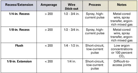
Like any welding process, MIG welding has its complications. Even so, there is no reason to let common problems slow you down. With a bit of knowledge and some solid troubleshooting skills, you can easily find the right solution to get back to welding—sooner than later. Consider the following guidelines to help you along the way. Porosity occurs when a gas pocket becomes caught in the weld metal. This discontinuity can appear at any specific point on the weld or along its full length, and/or on the surface or the inside of a weld. The result, regardless of the location, is always the same: a weaker weld. Inadequate shielding gas coverage is one of the most common causes of porosity. To correct this problem, first check the regulator or flow meter for adequate gas flow, increasing it if necessary, and check the gas hoses and the gun for leaks. Whether welding inside or outside, shield the arc and weld puddle from drafts with a welding screen. Next, confirm that the MIG gun nozzle is large enough for the application, as too small of a nozzle can prevent proper shielding gas flow. Keep the nozzle one-fourth to one-half inch away from the work piece, make certain it is free of spatter, and always use the correct contact tip recess. Slow your travel speed and hold the MIG gun near the bead at the end of the weld until the molten metal solidifies; pulling the gun away too soon can interrupt gas coverage and leave the setting weld vulnerable to the atmosphere. Additional causes of porosity include: using the wrong gas (always use a welding-grade shielding gas appropriate for the base metal and filler metal), using too much or the wrong type of anti-spatter (use the correct amount and type for your application) and extending the welding wire too far out of the nozzle (extend no more than one-half inch beyond the nozzle). Impurities in the base metal, such as sulfur and phosphorous in steel, or a dirty base metal can be further causes of porosity. If specifications allow, consider changing to a different composition of base metal, and always remove rust, grease, paint, coatings, oil, moisture and dirt prior to welding. Filler metals with added deoxidizers can help to “clean” the weld, but should never be solely relied upon to minimize porosity. Finally, replace any wet or contaminated shielding cylinders immediately. Undercutting occurs when a groove melts into the base metal next to the toe of the weld and the weld metal fails to fill that area. This discontinuity weakens the toe of the weld, increasing the chances of cracking. Correcting the problem is relatively simple: reduce the welding current, decrease the welding arc voltage and adjust your MIG gun angle toward the joint. Reduce your travel speed so the weld metal completely fills the melted-out areas of the base metal. When using a weaving technique, pause slightly at each side of the weld bead. When the weld metal fails to completely fuse the weld metal with the base metal or with the preceding weld bead in multi-pass applications, incomplete fusion can occur. Some people refer to this problem as lack of fusion. Generally, an incorrect MIG gun angle is the cause and you should adjust it accordingly. Follow these steps: If correcting the MIG gun angle does not remedy incomplete fusion, look to see if the welding puddle is too far ahead of the wire. If so, increase your travel speed and/or the welding current to correct the problem. Conversely, if you suspect insufficient heat input has caused incomplete fusion, select a higher voltage range and/or adjust the wire feed speed as necessary. Finally, always clean the surface of the base metal prior to welding to remove contaminants that may prevent the metal from fusing together. Another common MIG welding problem—spatter—occurs when the weld puddle expels molten metal and scatters it along the weld bead; this molten metal then cools and forms a solid mass on the workpiece. Excessive spatter not only creates a poor weld appearance, but it can also lead to incomplete fusion in multiple welding pass applications. Too fast of a wire feed speed, too high of a voltage setting, and too long of a welding wire extension, or stick-out, can cause spatter. Lowering the given settings and using a shorter stick-out can help. Like porosity, insufficient shielding gas and/or dirty base materials can cause spatter. As necessary, increase the shielding gas flow at the regulator and minimize drafts near the welding arc, clean and dry the welding wire, and remove all grease, dirt and other contaminants from the base metal. Other factors that can cause spatter are: the wrong size contact tip, a worn contact tip or the wrong tip to nozzle recess. Be certain you have the right contact tips, nozzles and recess parameters for the application. Excessive penetration occurs when the weld metal melts through the base metal and hangs underneath the weld. Excessive heat input is usually to blame for the problem. To correct this, select a lower voltage range, reduce the wire feed speed and increase your travel speed. Conversely, insufficient heat input can cause lack of penetration, or the shallow fusion between the weld metal and the base metal. Selecting higher wire feed speed, a higher voltage range and/or reducing travel speed are all viable remedies. Preparing the joint correctly also helps prevent lack of penetration—the preparation and design should permit access to the bottom of the groove and allow you to maintain proper stick-out and arc characteristics. Wire feed stoppages and wire feed system malfunctions can adversely affect the welding arc and create irregularities that may weaken the weld bead. Birdnesting, a tangle of wire that halts the wire from being fed, is a common problem. You can resolve birdnesting by flipping up the drive roll and pulling the wire back out of the gun. Next, trim the affected wire and re-thread it through the feeder and back to the gun. If the welding specifications allow, decrease the drive roll tension, use a larger diameter wire and/or reduce the distance the wire feeds (use shorter cables) to minimize the chance of birdnesting. Burnback is also very common. It results when a weld forms in the contact tip, and usually occurs because of too slow of wire feed speeds and/or from holding the MIG gun too close to the base metal during welding. To correct burnback, increase the wire feed speed and lengthen the distance of the MIG gun from the workpiece (the nozzle should be no further than one-half inch from the metal). Replace burnback-damaged contact tips by removing the nozzle and the contact tip (which may be melted to the wire), snipping the wire, installing the new contact tip and replacing the nozzle with one that has the appropriate tip recess for the application. Other causes of wire feeding problems include liner blockages, improperly trimmed liners (too short/burred/pinched) or the wrong size liner. To remedy these problems, replace any liner if you find a blockage, always trim the liner according to the manufacturer’s direction and be certain you are using the correct size liner for the welding wire diameter. Remember, quality MIG welds are the result of not only good welding technique, but also your ability to identify and solve problems quickly if they do occur. Continue arming yourself with some basic information and you’ll be able to tackle the most common problems associated with MIG welding without sacrificing time or quality.
There are regular job shops. Then there are job shops that go far beyond basic fabrication — ones that design, machine, laser cut, manufacturer and inspect specialty components from start to finish. Watson Engineering, Inc. of Taylor, Mich. is just such a one. What began as a one-person fabrication shop nearly thirty years ago is now a full-service manufacturer of prototype tubular and sheet metal components, along with products for the automotive and commercial industries. And whether its welding operators are retrofitting race cars with roll cages or manufacturing high-volume runs of heavy equipment components, Watson prides itself on one simple philosophy set forth by founder, Chuck Watson: “Customers come to Watson Engineering with problems they need help with – and we make the problems go away.” The company has been able to achieve this goal through a lot of hard work and even greater innovation. Not to mention, this job shop is lean. Every tool, every bin and every piece of welding equipment has its place — and that place has been chosen for maximum efficiency. In fact, the entire organization of Watson’s facility has been the result of all of its employees’ commitment to the company’s lean initiatives, from concept to painting and shipping. Not surprisingly, as part of its ongoing innovation and its lean initiatives, Watson decided to look as closely at its robotic welding cells, too. In doing so, they decided to convert to Tregaskiss’ TOUGH GUN I.C.E.® robotic MIG gun in order to solve a long-standing problem: finding a durable gun that could maintain its accuracy after a collision. They also added several of Tregaskiss’ air-cooled TOUGH GUN robotic MIG guns to other welding cells. After adding the products, they were surprised to find a few extra benefits that directly support their lean initiatives and have also contributed to a 25 percent increase in Watson’s overall productivity. Watson prides itself on the ability to produce components that have exceptionally intricate or complex designs. Not surprisingly, such designs can pose some particular challenges to the welding process, especially when the components are comprised of a wide range of materials and material thicknesses. According to Rafael Velasquez, robotic supervisor at Watson, in any given day the company may weld exhaust manifolds for an automotive customer, hood hinges for a commercial customer and thousand pound internal components for a heavy equipment manufacturer — sometimes in the same work shift and the same robotic welding cell. Not to mention, all the products undergo rigorous quality control testing (Watson even performs 100 percent lot tests on some parts), so quality is key and downtime is simply not an option if they are to create top notch products on a tight schedule. One of the biggest obstacles that Velasquez and his fellow Watson welding operators have faced over the years is finding a robotic MIG gun that could “take a hit without bending the neck” after a collision. Despite the best precautions, robotic welding collisions are a very real problem, resulting most often from tooling clamps not being secured. If the robotic MIG gun neck bends, it must be adjusted or replaced since the robot’s tool center point (TCP) will change and have a negative impact on the quality of subsequent welds. “We’re always changing parts and tooling,” explains Velasquez. “Unfortunately, you can bend two or three necks in a week because of it. Somebody would miss a clamp and leave it up. It happens.” After enough bent necks, downtime and just plain frustration, Velasquez opted to contact Watson’s long-time distributor, Dan Gnesda of Roy Smith Company in Detroit for help. Gnesda recommended the TOUGH GUN I.C.E. Robotic MIG Gun and the results, per Velasquez, have been worthwhile. Prior to converting to the TOUGH GUN I.C.E. robotic MIG gun, Watson used a competitive brand water-cooled gun, which Velasquez explains was quite costly and time-consuming to fix after a collision. Fundamentally, necks for water-cooled robotic MIG guns tend to be weaker than air-cooled designs and involve more work to replace, in major part because the water lines run internally through the power cable, gun and neck. To replace the water-cooled neck after a collision, Velasquez and his team needed to disconnect the neck from the gun and unhook the water lines by removing clamps that were crimped around them — a process that took about 30 minutes. Converting to the TOUGH GUN I.C.E. robotic MIG gun, however, seems to have offered Watson the best of both worlds: the durability of an air-cooled MIG gun and the cooling capacity of a water-cooled gun. I.C.E stands for ‘Integrated Cooling Enhancer’ and aptly describes the design of the gun, as it is a ‘hybrid’ between conventional air- and water-cooled designs. The TOUGH GUN I.C.E. robotic MIG gun features stainless steel water lines that run along the outside of the gun’s neck down to the nozzle, rather than through the neck like true water-cooled products. This design provides water circulation that keeps the consumables of the gun running cool, but because the lines are external (instead of running through the neck), the gun’s neck has more mass and is stronger, much like that on an air-cooled gun. According to Velasquez, the necks on the TOUGH GUN I.C.E. robotic MIG guns “can take the hit” most times after a collision, and in the event that the neck does bend, it can be replaced in about five minutes — a timeframe that fits nicely into Watson’s overall lean initiatives. The TOUGH GUN I.C.E. robotic MIG gun also features water shut-off valves at the I.C.E. connections and a quick-change neck feature. To disconnect the neck, Velasquez simply loosens a setscrew on the gun housing, disconnects the quick-change fittings for the water lines and slides on a new neck. After reconnecting the water lines and verifying his TCP, he can get the welding operation up and running again. “My emergency calls from Watson used to come through every other week with the previous gun, because of the crashes,” explains Gnesda. “After replacing the necks, there could be leaking or something else that was off. Now with the TOUGH I.C.E. gun, well, I hear from them every couple of months.” And because, the TOUGH GUN I.C.E. robotic MIG gun provides up to 550-amp capacity (at 60 percent duty cycle with mixed gases), it provides Watson with another solution that fits their goals for creating a lean facility: it can weld on a variety of material thicknesses. There is no need to change out robotic MIG guns to accommodate for the ever-changing flow of components that make their way through the weld cell each day — a factor that saves Watson money and time. “We have a lot of high amperage, high voltage welds. And we weld on thinner metals, too,” explains Velasquez. “Some of our components are thirty-millimeters thick and others are as thin as three mils. I can weld both. I just have to change out the wire.” As with the durability of the gun’s neck and the occasional changeover, being able to use the same gun for all its parts has contributed significantly to Watson’s lean initiatives. “There’s so much going on here with all the parts they weld, it’d be very easy for things to get out of control.” says Gnesda, “But these guys have a handle on everything. I think the I.C.E. is helping with that.” The goal of Watson’s lean initiatives has been to improve workflow, minimize downtime and, of course, improve productivity and profitability. After converting to the TOUGH GUN I.C.E. Robotic MIG Gun, and also adding several Tregaskiss® TOUGH GUN® robotic MIG guns to their other welding cells, Watson found that their equipment maintenance also became easier and they reduce their inventory, too — both benefits they had not anticipated. Velasquez first noticed that the total cost of maintaining the TOUGH GUN I.C.E. robotic MIG gun was substantially lower compared to the conventional water-cooled MIG gun Watson used previously. In addition to the fact that the necks have been more durable and easier to replace when needed, he found that the gun’s unicable has been equally robust. In fact, according to Velasquez, he only just recently changed out the original unicable that came with the TOUGH GUN I.C.E. robotic MIG gun two and a half years ago. “We’ve been running around the clock, six days a week each year with the same one,” he explains. “To change it, I just loosened a couple of screws, popped it out and put on the new one. With the addition of a new liner, I just connected the unicable back at the feeder. It took me fifteen minutes and we’re done.” Saving the cost of purchasing unicables on a regular basis has been a welcome benefit for Watson, as has its reduction in inventory for this and other MIG gun parts. Since Velasquez began using the TOUGH GUN I.C.E. robotic MIG gun and the air-cooled TOUGH GUN MIG guns for his other welding cells, he has also been able to reduce his inventory for necks significantly, too, as many are interchangeable. “I used to have so many necks in stock, sometimes about fifteen different ones. Now I’ve got three necks I can use on all the robots. I don’t have to have so much inventory to keep this place running,” says Velasquez. He’s also been able to reduce his consumables inventory. Both the TOUGH GUN I.C.E. Robotic MIG Guns and the standard TOUGH GUN MIG Guns operate on Tregaskiss’ Common Consumable Platform, meaning that the front-end consumables — nozzles, contact tips, retaining heads and liners — are the same for both guns. Velasquez explains that he uses standard and heavy-duty TOUGH LOCK® consumables for all the guns, depending on the thickness of the parts his robots are welding and at what amperage. He simply orders the parts that correspond to the different wires he uses between part runs. Velasquez also explained that when he changes over the contact tips on his robotic MIG guns, he then uses them for the semi-automatic MIG guns Watson uses in other portions of the facility. So what’s the bottom line of these and all the other benefits Watson has found with its lean initiatives? According to Velasquez, Watson’s lean initiatives — including the benefits brought forth from the TOUGH GUN I.C.E. robotic MIG guns and other Tregaskiss products — have combined to provide a 25 percent increase in the company’s productivity. The process is ongoing, of course, but it’s been made easier by the commitment of Watson’s employees who have all played a significant role in organizing the facility, from the concept phase of the many components it manufactures to the machining, storing and assembly of the parts. Having a durable, easy-to-maintain robotic MIG gun and minimizing Watson’s inventory has definitely helped improve workflow and reduce downtime, too. “We’re serious about lean,” says Velasquez. “We try to complete jobs from concept to finish within days. The I.C.E. and other Tregaskiss products have definitely helped us.”
The economy is in bad shape right now, but when it improves, the graduates of San Diego Continuing Education’s welding program will be well positioned to fulfill the need for skilled welders. Now in its 35th year, the school focuses on adult education for unemployed and underemployed San Diego-area residents. Its curriculum is narrowly tailored to the needs of local industries — specifically shipbuilding, construction and manufacturing. The school provides free training to any California resident and currently has 96 students and a waiting list of an additional 58 people. “Our program is set up to provide the student with experience on the same types of joint configurations, metal types and welding processes that they’re going to need when they enter the workforce,” explains welding instructor Bill Borinski. The program, which spans a minimum of 600 hours over 24 weeks, also prepares the students with the skills to obtain an AWS D1.1 (American Welding Society) Unlimited Certification by passing a visual and x-ray weld evaluation. Even with the school’s focused, industry-driven curriculum, there is still a vast amount of knowledge and skills to impart to the students, and the school strives to make every minute count. That, explains Borinski, is why it is so important for the school to have durable, time-saving welding equipment. “Downtime in business costs money — for us it costs knowledge,” he says. “If a student’s equipment is down, then he’s not learning. Our students have enough to concentrate on as it is, they shouldn’t have to worry about whether their equipment is working properly or not.” The school recently converted its welding labs to Bernard™ Q-Gun™ and Dura-Flux™ MIG Guns and Centerfire™ Consumables to prevent such problems. The guns and consumables came packaged with the school’s new power sources and wire feeders, and Borinski said he’s been very satisfied with the results. The program has been running the guns for 12 hours a day, four days a week, and there hasn’t been a single malfunction. The Centerfire consumables system has reduced student downtime and frustration, while also improving weld quality. In this open-enrollment program, students work on the material at their own pace until they master the skills required to graduate. New classes, which meet for 6.25 hours a day, four days a week, begin every month, and students can stop and start the program at their discretion. Students learn an AWS-certified curriculum in self-shielded and gas-shielded flux-cored welding on 3/8- to 1-inch mild steel using E70T-1 and E71T-8 welding wire. Students briefly learn the GMAW process, but the program spends the majority of its time providing specific skills that are needed immediately in local industries. They focus on building proficiency in all welding positions on butt, corner and T-joints. The school uses Bernard Q-Gun MIG Guns for its gas-shielded flux-cored and MIG training. Borinski noted that the gun’s curved handle reduces his students’ muscle fatigue after welding for long periods of time, and that the guns also improve their mechanical leverage, making it easier for the students to hold the guns in flat and horizontal welding positions. “What my students and I love about the Q-Gun handle is that when you put it in your hand, it’s already in a position to weld,” Borinski said. “If the MIG gun is putting strain on my students’ wrists, they’re going to be sore and miserable by the end of the day and they’ll probably lose some of their enthusiasm for a career in welding.” The Centerfire system further reduces his students’ educational downtime and frustration levels, Borinski said. By using a threadless contact tip with a large diameter tapered base that fits snugly into the diffuser and is locked in place by the nozzle, the Centerfire consumables make it nearly impossible for students to set incorrect contact tip recesses or for the tip to come loose inside the nozzle. “With our old brand of consumables, if we didn’t screw the contact tips in properly they would come loose and literally fly out of the end of the gun. That can really add to the frustration of a beginning welder,” Borinski said. While he is pleased with the guns and consumables, Borinski noted that it’s Bernard’s customer service that will keep him as a customer when their equipment eventually needs to be replaced. “To us, a gun is a gun,” Borinski said. “We can figure out on our own how it operates. Still, we were really impressed when a Bernard representative came out and offered to exchange any of our guns for free if the stock model didn’t perfectly fit our lab set ups.” Bernard’s Gun Exchange Program allows any one who receives a standard Q-Gun or Dura-Flux MIG Gun as part of a power source or wire feeder package to exchange the unused gun for a new gun with different cable length, neck, handle or trigger configurations. Bernard also provided Borinski with product information and support prior to and following his purchase to ensure the guns and consumables he ordered would meet his needs. “Sometimes the educational community gets sheltered from a lot of the outside activities that are going on. We don’t get exposure to the different equipment options that are out there,” Borinski said. “When Heidi Ewoldt, Bernard’s Inside Technical Sales Manager, called us and spent time explaining all of the equipment options and configurations available, it told us that Bernard wanted more than a quick sale. They were committed to our success.” “We’re running some pretty hot, high-amperage applications here,” Borinski said, “and we have had zero failures — zero internal issues, zero electrical issues. We haven’t even needed to change the liners on some of the guns.” Like Bernard, San Diego Continuing Education understands the value of strong partnerships and adapting its products to its customers’ needs. In order to meet the evolving demands of area industries, Borinski meets annually with an advisory committee composed of business and union leaders to discuss the skills and knowledge they look for in new employees. “If we taught what we wanted to teach and not what the employers in the area need, then we’re sending them people they can’t use and wasting our students’ time,” Borinski continued. “We must have our pulse on the industry in order to be a relevant educational institution.” In the last few years, Borinski said, the advisory committee has been asking for employees with “soft skills,” such as blueprint reading, teamwork training, lean manufacturing processes and other skills that go beyond laying a weld bead. “The job market is very competitive now,” Borinski said, “and those students with additional skills, who can add value to the organization, are going to have a significant advantage during the interview process.” That’s why the school partnered with the AWS to form a curriculum that provides students with the knowledge and skills they need to become AWS Certified Unlimited in FCAW upon graduation. The unlimited designation is a guarantee that the student can perform code-quality welds in the 1-G, 2-G, 3-G and 4-G positions using the FCAW process. This certification, combined with the schools blue print reading and teamwork curriculum, gives graduates a strong advantage when applying to one of the area unions, Borinski said. The school’s approach to welder training has resulted in numerous opportunities for its graduates in area businesses. One example is the school’s partnership with General Dynamics NASSCO, one of the San Diego’s largest employers. Through the partnership, General Dynamics NASSCO has hired over 400 of the program’s graduates in recent years. The main reason San Diego Continuing Education tried the Bernard guns and consumables was that they came packaged with the wire feeders and power sources the school purchased. Still, after using them without a single failure for the last 18 months, Borinski said one of the first questions he will ask when purchasing new equipment will be whether they accept Bernard guns and consumables. Luckily for him, Bernard’s products are adaptable to almost all major power source and wire feeder brands.
For some companies, choosing between an air-cooled or a water-cooled MIG welding system is pretty cut and dry. Mobile fabrication and repair companies that weld sheet metal for only a few minutes every hour will have little need for the benefits provided by a water-cooled system. Likewise, shops with stationary equipment that repeatedly weld at 800 amps probably won’t be able to find an air-cooled system that can handle the heat of the application. But for many companies, however, it’s not such an easy decision. Each type of cooling system has advantages and disadvantages, and deciding which is right for your company requires a careful analysis of the following factors: Keeping MIG welding equipment cool is necessary to protect the power cable, gun and consumables from damage due to the radiant heat from the arc and the resistive heat from the electrical components in the welding circuit. It also protects the operator from heat-related injuries and provides more comfortable working conditions. A water-cooled MIG welding system pumps a cooling solution from a radiator unit, usually integrated inside or near the power source, through cooling hoses inside the power cable and into the gun handle, neck and consumables. The coolant returns to the radiator where the radiator’s baffling system releases the heat absorbed by the coolant. The ambient air and shielding gas further disperses the heat from the welding arc. An air-cooled MIG welding system relies solely on the ambient air and shielding gas to dissipate heat that builds up along the length of the welding circuit. Air-cooled systems use much thicker copper cabling than water-cooled systems, which allows the cable to transfer the electricity to the gun without building up excessive heat from electrical resistance. By contrast, water-cooled systems use relatively little copper in their power cables because the cooling solution carries away the resistive heat before it builds up and damages the equipment. The welding amperage will be an important factor to weigh when deciding between an air- or water-cooled system. In general, air-cooled systems are better for low amperages and water-cooled systems are better for high-amperage applications. Air-cooled guns are available with ratings from 150 – 600 amps, and water-cooled guns range from 300 – 600 amps. These ratings represent the current loads under which the guns become so warm that they are uncomfortable for the average operator to hold. Because guns are rarely used to the limits of their duty cycle, it’s often a good idea to purchase a gun that’s rated to a lower amperage than the maximum to which it will be exposed. For example, a 300-amp gun can handle more than 400 amps and it is substantially lighter and more maneuverable than a 400-amp gun. Closely related to a gun’s amperage capacity is its duty cycle — the amount of time during a 10-minute cycle that the gun can operate at its rated capacity without becoming uncomfortably hot. Exceeding a gun’s duty cycle can lead to operator pain and will also reduce weld quality and decrease the service life of the gun and consumables. There is no industry standard for establishing amperage ratings based on duty cycle, so two guns both rated to 400 amps could have significantly different duty cycles. This makes it important for the customer to consider a gun’s amperage rating and duty cycle together in order to form an accurate assessment of the MIG gun’s capabilities. Welding all day long in an industrial or construction environment can take a significant toll on the hands, arms, shoulders and back (not to mention most other body parts) of a welding operator. A heavy, bulky and difficult-to-maneuver gun only exacerbates these aches and pains, and it accelerates the time they take to set in. One of the benefits of water-cooled guns is their size and weight. Because water is more efficient than air at carrying away heat that builds up from the heat of the arc and electrical resistance, water-cooled guns use less wire for their cables and smaller gun components, resulting in reduced operator fatigue. Although air-cooled guns are generally heavier and more difficult to maneuver than water-cooled guns, significant differences in gun design between manufacturers can also have a big impact on how quickly the gun contributes to fatigue. It’s a good idea to physically hold a gun to determine its comfort level prior to making a purchase. Because water-cooled guns require more equipment than air-cooled systems, they can be impractical for applications that require portability. Transporting the cooling system and coolant hoses of a water-cooled MIG gun can reduce productivity and cause unnecessary downtime. Water-cooled systems are most practical in applications where they will be stationary or moved very little. By contrast, air-cooled MIG guns are easily carried and moved from site to site within a shop or out in the field. Finally, companies must evaluate the cost of the two systems before making a purchasing decision. Doing so, however, is not as simple as looking at their respective price tags. In addition to the sticker price of the systems, companies need to consider maintenance costs as well as productivity and downtime costs associated with operator fatigue and equipment longevity. A water-cooled system requires the purchase of a coolant flow system (including radiator, pump, hose lines, etc.), which leads to a higher up-front cost than an air-cooled system. Because water-cooled systems require a special coolant solution in order to avoid mineral or algae build-up in the coolant lines and radiator, they involve more extensive maintenance and higher operational costs than an air-cooled system. Furthermore, coolant leaks can lead to equipment damage and weld discontinuities that add to the cost of owning a water-cooled system. In addition to being less expensive up-front, an air-cooled system also offers the advantage of being better suited to low amperage applications. Thus, for example, a company that needs to weld at 150 amps and 600 amps in the same weld cell can keep its costs down by purchasing a single air-cooled system rather than a water-cooled system for the high-amperage applications and an air-cooled system for the low-amperage applications. That doesn’t mean, however, that a water-cooled system is more expensive than an air-cooled system. As mentioned earlier, a water-cooled MIG gun is much smaller and more lightweight than an air-cooled MIG gun, which can help decrease operator fatigue and increase productivity over the course of a day. When set up properly, a water-cooled MIG gun can provide significant long-term cost savings compared to an air-cooled gun. The coolant in a water-cooled system also extends the service life of the consumables by drawing away the heat absorbed from the arc. Longer consumable life means less downtime for changeovers and lower consumables inventory. Unfortunately, there is no one-size-fits-all formula for choosing between an air-cooled and a water-cooled MIG welding system. Each company must analyze their welding operations and determine which type of system offers the benefits most important to them. Considering these factors — cost, worksite location, gun weight and operator comfort, duty cycle and amperage requirements — will provide a good start toward making a wise decision. Find an air– or water-cooled MIG Gun for Your Application
Worldwide, companies serving the automotive industry have faced a unique set of challenges in the last several years. Still, as the economy begins to rebound, each must find ways to maintain their productivity and profitability — often with fewer employees than before the recent recession. A large part of maintaining that productivity is to ensure high levels of uptime in the robotic welding operations. Conventional problems like spatter, burn-through and poor part fit-up often hinder such attempts, as do issues like managing large amounts of inventory and contending with downtime to service welding equipment. Unfortunately, there is no single answer to these challenges. There are, however, some considerations that may help reduce suppliers’ pains and assist in other interrelated parts of the process. The recent increase in demand for production is causing some automotive suppliers, especially those in North America, to make capital investments that they previously postponed during the recession. When possible, standardizing on a single brand and style of welding power source, robotic controller, and GMAW gun and consumables during this investment can streamline inventory and maintenance procedures. For companies in organic growth mode with new programs and/or Greenfield operations, this standardization can help in long-term equipment re-deployment to other facilities, as well as streamline the manpower learning requirements. For companies that are in acquisition mode, however, this standardization may not be feasible. Instead, these suppliers should, at a minimum, consider standardizing on a single brand and style of robotic GMAW guns and consumables to minimize inventory. Doing so can also reduce the risk of improper consumable installation, which can lead to unscheduled downtime to rectify. Many automotive suppliers rely on tandem welding processes as a means to generate greater productivity. In recent years, however, advancements in single arc pulsed technology have proven very efficient in providing faster travel speeds and minimizing spatter. This technology, which effectively lowers the average amperage level during welding (by regularly switching the current between high peak amperages and low background amperages), is also quite easy to operate. Given the reduction in workforce in the automotive industry, combined with an overall shortage of skilled welders, this less complex (but highly efficient) technology has already proven beneficial for many automotive suppliers. Automotive suppliers, particularly those with multiple locations, may want to consider purchasing their robotic GMAW guns, peripherals and consumables from a single source vendor or welding distributor. Having multiple vendors may appear to provide cost savings up front; however, a per-item approach can actually increase the total spend. Instead, by single sourcing a product line, a company is better poised to maximize their purchasing power with one vendor and gain loyalty discounts. The vendor may also be more inclined to aid in new efficiencies and technologies. Plus, a trusted single source vendor can often help automotive suppliers assess their total consumable and robotic GMAW gun usage, streamline inventory and reduce costly paperwork at the same time. In addition to standardizing equipment when possible, using welding products that minimize the opportunity for errors is an important part of keeping the welding process flowing and reducing operator error. For example, nozzle detection (i.e. that doesn’t increase cycle time) can eliminate the potential of excessive rework or scrap. Avoiding errors in equipment installation is also critical, as missing or incorrectly installed components on the front end of a robotic MIG gun can cause them to become electrically alive, causing premature failure and poor welding performance. When possible, suppliers in the automotive industry should work with equipment manufacturers and vendors or welding distributors who can engage regularly in best practice meetings. These meetings can occur by conference call or in person, and can help determine what practices in the welding operation are working most effectively and what areas need improvement. Open issues can be prioritized amongst a group for time-phased solutions. These meetings can especially help companies with multiple locations, even globally, to identify opportunities for changes that could positively affect other facilities. They are also an excellent platform for brainstorming error-proofing ideas and serve to open communication among the parties involved in the success of a company’s welding operation. Even though preventive maintenance or PM may have become a commonplace buzzword in recent years, the fundamentals are still critical to providing good welding performance and reducing unscheduled downtime in the automotive industry. Companies should always take care to inspect connections in the GMAW gun, wire feeder, consumable and ground cables on a regular basis. Replacing worn components during scheduled downtime (at the beginning of a shift, for example) can help prevent problems during production. As of yet, “predictive maintenance” —– technology that alerts when consumables need to be changed – is not available. In the meantime, however, companies can instead track contact tip usage to gain an understanding of how often these components need to be replaced. Non-subjective analytical processes should be used to benchmark component longevity and performance. During Best Practice meetings, “Coopetition” can be an integral part of maintaining an effective welding operation for the greater good of the customer. This term refers, in short, to cooperation that occurs between competitive equipment manufacturers. The reality of any welding operation is that the manufacturer of the robotic GMAW gun or welding wire may be in direct competition with the company whose power sources are in an automotive supplier’s weld cell. Even so, finding equipment manufacturers who are willing to work together to address problems in the welding operation is key to resolving issues when they arise. A problem with the contact tip, for example, is usually a “barometer” of other things happening in the process. In short, it is very often a symptom of a problem, as opposed to the root cause. Having partners who are willing to put aside competitive differences for the good of resolving problems like these is important to gaining good welding performance. As is typical in automotive “just-in-time” applications, suppliers want to reduce instances of work-in-progress (WIP) and keep parts flowing (Takt time). To continue that work flow but still allow for any instances of stoppage in a robotic welding cell, suppliers may consider building a buffer into production. For example, if a company has a production line of 40 welding robots, breaking that line into fifths (five sections of eight robots), allows them to address any instances of consumable failure while causing a stoppage of only eight robots instead of shutting down production on all 40. That buffer can mean a significant difference in terms of lost production and money. And while no single one of these considerations can ensure the levels of productivity and profitability to which automotive suppliers strive as production demands increase, they can be a step in the right direction. Automotive suppliers should consider working with a trusted welding equipment manufacturer and vendor to discuss a plan for assessing their robotic welding operation and identifying opportunities for improvement.
The automotive industry has certainly begun to show signs of rebounding from the economic downturn; however, companies are now being asked to “do more with less” as production volumes approach the levels of several years ago. More than ever, companies require operational efficiencies to maintain process flow and avoid unscheduled downtime of automated equipment. Commonly, arc-welding process challenges have a significant impact on achieving production goals and maintaining efficiency. Typical contributors to arc-welding process inefficiencies include poor part fit-up, tool center point (TCP) repeatability, spatter and managing consumable changes. Effectively managing these elements are essential if companies are to meet their quality requirements and fulfill a high-volume production demand. As the automotive industry continues experience an upswing in production—up 12.16 percent year-over-year through March 19, 2011 (Automotive News)— maintaining an effective and efficient operation will become even more challenging. Reductions in the workforce over the last several years have left the industry with fewer employees to monitor welding operations and the overall shortage of skilled welders has compounded the challenge. Whereas 10 years ago a large automotive supplier may have had one welding technician for 20 robots, today that ratio has increased to as few as one welding technician for every 50 robots – or more. Clearly, the lack of resources creates challenges but eliminating non-value-added activity (or that which doesn’t contribute directly to throughput) can help overcome those. Practices such as equipment standardization, preventive maintenance and product selection can promote a Leaner operation and provide opportunities to improve process flow and operational efficiency. In recent years, the consolidation of automotive suppliers and facilities has resulted in welding operations made up of multiple styles and brands of welding equipment, including power sources, robotic controllers, robotic manipulators and GMAW guns. The outcome is often a wide breadth of products to manage and, with fewer resources, an increased potential for costly errors and unscheduled downtime. Not surprisingly, in an industry that requires repeatable, high-volume welds—some up to 500 parts in a single shift—consistency is critical and any deviation in quality could result in downtime, scrap or rework. Ideally, standardizing on a single GMAW gun brand can help companies in the automotive industry avoid unscheduled downtime for changing out incorrect consumables or reworking quality issues. It can also reduce the amount of time spent managing inventory and provide a built-in poka yoke (mistake-proofing) system by eliminating (or significantly reducing) the opportunities for incorrect installation. Some companies have found that such standardization, along with a vendor-managed consumable system works well and contributes positively to their goal of maintaining process efficiency and equipment utilization. The process of standardization may take time—replacing older GMAW guns as they wear, for example—but in the long term it can yield positive results in quality, performance and cost. It also allows the production team to have one point of contact for technical support should questions arise about the performance of a GMAW gun or consumable, as opposed to having to contact multiple manufacturers. To help with the transition to one GMAW equipment supplier, front-end conversion kits are widely available and allow companies to standardize on a single brand of consumables, regardless of the type of GMAW gun being used. These kits are a good alternative to replacing an entire fleet of GMAW guns, while still offering the benefits of standardized inventory. In some cases, there is an opportunity to maximize the value of welding consumables by using the same contact tips and nozzles for semi-automatic applications (such as those for repairs or rework) after they are too worn for the robotic application, which further reduces inventory. Most welding technicians, supervisors or operators in the automotive industry will attest to the fact that proper part fit-up is a constant concern. But not only do the parts that move into the weld cell need to be of the proper dimension and fit, the GMAW welding gun and consumables being used also need to provide accurate, repeatable and durable performance. Robotic GMAW guns are intended to weld at the same location every cycle by providing a consistent tool center point (TCP). Some products are more durable than others but they all require preventive maintenance to optimize performance and prevent unscheduled downtime for replacing items like contact tips or liners. Air-cooled robotic GMAW guns are the most durable product available. Many applications in the automotive industry, such as suspension components, use thin materials—2 to 4 millimeters—that are ideal for an air-cooled robotic GMAW gun since the typical operating range is approximately 200 to 300 amps at an average of 60 percent duty cycle. Water-cooled products improve performance at higher duty cycles yet they are inferior to air-cooled products from a durability perspective. This is primarily due to the addition of water channels and other mechanical requirements of a water-cooled design. In the automotive industry, it is rare to experience applications that truly require a water-cooled GMAW gun. Even for end users welding thicker base metal (truck frames, for example), they are still likely to be within the comfortable range of an air-cooled GMAW gun. In some cases, however, the addition of water-cooling will help manage excessive heat and prolong the life of welding consumables (e.g., nozzles and contact tips). In these instances, there exists an opportunity to use a hybrid air-cooled/water-cooled gun. This type of product has the underlying construction and durability of an air-cooled robotic GMAW while offering some of the benefits of a water-cooled solution. Regardless of the welding application, it is important for companies to use the most appropriate type of GMAW gun for the job and properly maintain the equipment to ensure a maximum return on investment. Good preventive maintenance procedures include inspection of all connections in the entire system: GMAW gun, wire feeder and ground cables, and more. Other opportunities include regular inspections for proper wire feeding and proactively replacing worn components during scheduled downtime, rather than during production. Such activities can occur prior to a shift beginning and may help avoid unnecessary interruptions to welding during production. As the automotive industry returns to the production levels of several years ago, taking steps to standardize inventory, implement good preventive maintenance techniques and select the right product are means by which companies can become more efficient and “do more with less.”
Making the decision to automate your welding process isn’t something to be taken lightly. It requires a careful assessment of your current welding process, a detailed plan to automate and, in most cases, the ability to justify the capital expenditure—tasks that together can take months to complete. Still, automating your welding process can bring many advantages that make the work worthwhile. These include: increasing productivity, improving weld quality, and lowering material and energy costs, among other benefits. In many cases, you can also obtain a quick return on your investment through such advantages. The key to successful automation is to consider some important factors before purchasing and implementing your robotic welding system. Transitioning to an automated welding system can dramatically increase production; however, it should never been done impulsively. It is expensive and does not suit every application or facility. Instead, prior to implementing an automated welding system, work with an integrator or robot OEM to develop a plan that accounts for factors including: the part and volume to be automated, your facility and available personnel for overseeing the system. Completing an upfront evaluation of your current welding process, as well as the outcome you desire is a good place to start. It will also help you avoid implementing an automated welding system that requires constant supervision. After all, the goal is to have an automated process that requires only nominal supervision, while still improving productivity and weld quality. A good first step is to consider whether you need a fixed or robotic welding system. Fixed automation is extremely efficient and cost-effective, and works well for welding parts that requires straight or curved welds along a single plane. An example would be a lathe-type application in which a simple part is spun, welded and ejected from the process. Another example would be a straight-line weld, in which the torch advances, makes a six-inch weld and retracts to the neutral position in preparation for the next weld. Conversely, a robotic welding system features guns mounted on arms with articulated joints that can reach, rotate and pivot to gain access to the part. They can be programmed to complete more intricate welds than a fixed automation system. If you anticipate frequent job changes or need to weld complex parts, this type of automation can offer the flexibility to be re-tasked as needed. Also, think of your company’s future welding needs when determining which type of automation is best for you. For example, if you currently weld a part well suited to a fixed automation system, but you aren’t certain you will be welding that part three years from now, consider a robotic welding system. It can be reprogrammed and retooled to accommodate your needs in the future. Regardless of the type of automated welding system you choose, these systems are significantly faster than semi-automated welding, provided the process suits the application at hand. Simply put, your application needs to be repeatable. Parts with large gaps, fit-up or access challenges are best left to a welding operator who can weld in obstructed or precarious positions and compensate for such conditions. Similarly, parts that require intricate clamping and tooling to hold them in place will often hinder the productivity benefits of an automated welding system. Instead, if you are considering an automated welding system, be certain that the parts manufactured upstream are as simple and consistent as possible, and that they allow the robot to execute the weld repeatedly. Working with a robot OEM or integrator is a good way to determine if your parts are well suited to an automated welding system. Provide them with a blueprint or an electronic CAD drawing of the part you wish to weld. Doing so helps improve the quality of the planned weld and determine how the part and its tooling can be fine-tuned to optimize the automated welding process. Prior to automating, you should also assess the parts flow. For example, if you want to your automated welding system to relieve a bottleneck at the welding cell, then be certain that there are no delays in upstream part fabrication. Similarly, you should ensure that there is no rework required before sending parts to the welding cell or that the employees supplying parts to the robot can match the cycle time of the automated cell. After all, the efficiency of each of these situations directly affects efficiency of the automated welding system—if they are too slow, they can cause significant downtime and negate the speed sought through an automated welding system. If you cannot guarantee fast upstream workflow, you may want to consider an automation solution for upstream applications. These machines feature sophisticated part recognition systems that can pick up parts, manipulate them to the correct orientation and deliver them to the automated welding cell. These systems add to the expense of automating; however, they may be an option if you are concerned about the consistency and cycle time of your manual upstream processes. You might consider working with a third-party integrator to help you decide whether your facility suits the installation of an automated welding system. System integrators are knowledgeable about all aspects of facility modifications necessary for automation, including important safety regulations that apply in the fabricator’s region, country or state, in addition to those specified by OSHA and RIA (Robotic Industries Association). That said, the first step in assessing your facility is to determine your available space. Remember, the physical footprint necessary for a robotic welding system, as well as the room needed for the flow of raw materials is significantly greater than that of semi-automatic welding processes. By considering your available real estate, you can be certain that you have not only the physical space to accommodate the new system, but you can also avoid having to customize products, such as unicables, peripherals or torches to fit the work envelope. Instead, you can rely on standard products that will work within your allotted area. And, don’t worry if you have a small facility. There are still ways to make automation work. One option is to purchase fewer pieces of automation equipment that are capable of performing multiple tasks. Regardless of the size of your facility, you should also consider the power sources required to operate an automated welding system—a 480-volt three-phase power source is usually considered optimal. Also consider your gas and wire requirements. Due to the higher volume of welding possible with an automated welding system, you will need to purchase, store and place larger packages of wire (for example, 600 or 900 lb. drums compared to 40 lb. spools). In terms of gas delivery, limiting robot downtime is the top priority. Investing in bulk delivery of gas and using a manifold system can eliminate the downtime associated with frequent bottle change-outs and is key to adding to the productivity of an automated welding system. Automated welding systems need human supervision and maintenance. When considering whether to automate your welding system, you should evaluate the skill set of your available welding operators, as well as the resources you have for training them. The personnel who are most viable for training (and ultimately the oversight of your robotic welding system should you proceed with the purchase) are skilled welding operators or those with previous robotic welding management experience. These individuals should, after training, have the skills to program the robot and to troubleshoot the automated welding process as needed. They should also be able to perform routine, preventive maintenance on the system, as it can significantly decrease downtime in the long term and increase the life of the system and its components. Consider vetting robot OEMs to determine the availability and costs associated with the training of your personnel. Typically, robotic integrators and OEMs training, which usually lasts one to three weeks depending on the certification level desired. Also, look for robot OEMs or integrators that have resources available after the training has been completed. These resources may include online tutorials or troubleshooting information, additional onsite training and/or service team members you can reach by phone with any questions you and your team may have. Finally, before transitioning to automation, you will need to justify the expense—either to your superiors, or to yourself if you are the decision maker. To do so, first consider whether the volume of parts you need to produce necessitates automation. Remember, the key benefit of an automated welding system is the ability to produce high volumes of quality welds. If you have a smaller facility with lower runs of parts, however, you may still be a good candidate for an automated welding system. With the help of the integrator or robot OEM, you may be able to select two or three smaller volume applications and program a robot to weld those different parts instead. Calculating payback requires you to assess your current part cycle times and compare them to the potential cycle times of an automated welding system. Determining this volume is a critical factor to estimating your potential return-on-investment, as up to 75 percent of the cost of a semi-automatically welded component is the labor. That said, even if you will produce the same number of parts, you might be able to justify the investment by the amount of labor you can reallocate elsewhere in your operation. Specifically, you can use the skills of your semi-automatic welding operators toward the completion of challenging welds that cannot be completed with an automated welding system—adding further to your overall productivity. Smaller companies that transition to an automated welding system, or those with frequently changing parts, often seek a shorter payback period (no more than 12-15 months) in order to justify the investment. Conversely, if you know that your production needs will not change for years, you may be able justify a longer payback period. Remember, the key to successful automation is planning. Work with a trusted integrator or robot OEM to assess your current welding process and to determine the best type of automation for your application. Don’t forget to consider your available personnel, options for training and any facility accommodations needed for a new automated welding system. Each of these factors is crucial to realizing the advantages of automation and can help you achieve a faster return on the investment.
Measuring the value of a welding gun can be difficult when the gun is working properly. It’s those times when the gun is malfunctioning and you’re losing valuable production time trying to clear out a bird’s nest, change your fifth contact tip of the day or repair a shorted out power cable that the importance of the welding gun becomes clear. As one of Arizona’s premier handrail fabricators, Hot Az Hell Welding and Fabrication learned first hand the value of a welding gun when they began upgrading the majority of their equipment from Stick to the flux-cored process. While upgrading, company president Shawn Moreland didn’t think much about the flux-cored gun he would purchase and made his decision strictly based on price. Then, he and superintendent Chris Rice worked side-by-side on a project while Rice used a Bernard Dura-Flux™ gun instead. “I would be getting birds nests several times a day with the gun I purchased, and each time it would happen, Chris would have to come over and fix it for me,” Moreland recalls. “It would take him off his work and up to 10 minutes to fix. That whole week Chris didn’t have a single birds nest with the Dura-Flux, and eventually we realized it was the gun that made the difference.” They outfitted Moreland’s wire feeder with a Dura-Flux and he didn’t experience a single bird’s nest for the rest of the job. “We just threw the other gun away,” Moreland said. “After I got a chance to use Chris’ gun, I was 100 percent sold on Bernard.” As pleased as they were with the lack of downtime from repairing birds nests, Rice and Moreland have been even more impressed with the gun’s durability. “It gets pretty hot here, and the last thing my guys want to worry about is babying their welding equipment, so we end up putting the guns through some serious abuse,” Moreland explained. “I know you’re not supposed to, but we use the guns to drag our feeders all over a job site and the fact that they’re still working really tells me something about the quality of the gun.” Quality is something that Moreland, Rice and the other three Hot Az Hell employees, know a lot about. In over 20,000 linear feet of hand rail fabrication, they can boast that they have not had to make a single repair. “We have a flawless record with the register of contractors,” Moreland said. “We have dozens of general contractors that recommend us for federal, state, local and even residential projects, and we owe a lot of that to Chris’ commitment to high-quality welding.” The company specializes in hand rail fabrication, but also takes on a wide variety of welding jobs, including a recent project in which they welded five railroad cars together to form a bridge over the Central Arizona Project (CAP) Canal. Given the company’s history, it’s no surprise that an exceptional welding track record grew out of exceptional personal chemistry between Moreland and Rice. The two men became best friends while working as first line supervising foremen at an Arizona gas utility. “We formed a really tight bond back then because we were the only two that we could rely on within the company,” Moreland recalls. Both Moreland and Rice left their jobs to start their own businesses within a year of each other. Moreland said he frequently attempted cajoling Rice into working for him, and finally in 2006 Rice acquiesced and closed his business in order to join Hot Az Hell. From modest beginnings in 2006, Hot Az Hell has grown from an annual gross $160,000 their first year to projections of over $800,000 in 2009 — all with a five person staff. As of early 2009, the company was booked solid through mid-2010 with contracts to install over 32,000 linear feet of hand rail, including two of the largest projects in the Arizona Department of Transportation’s history — the widening of U.S. Highway 60 in Mesa and the Hoover Dam Kingman Highway expansion project. Moreland said the friendship among his employees, and their willingness and ability to take on virtually any of the work the company performs is a major contributor to their success. “We’re a very tight knit group. We’re more like a family than a company, but we also understand the business aspect of it as well,” Moreland said. “With a company our size, especially with the economy in a recession, everyone needs to be very versatile and able to take on whatever tasks the job demands.” Another key to the company’s success is Moreland’s confidence in the fabrication and welding expertise of Rice, the company’s ‘MacGyver.’ For his part, Rice said he is continually on the lookout for products and technologies that increase the company’s productivity and operator efficiency. As an example, during the recent CAP Canal project, the company was told they would need to use 7018 stick electrodes to weld the rail cars together, but after the first day of welding the pan decking using the stick electrodes, Rice asked the project inspector if they could use a structural flux-cored wire. They were allowed to use the flux-cored wire, and the following day, they produced four-times the welds of another crew member who was still using the 7018 rods. “They were losing several thousand dollars an hour every day that they couldn’t get their cranes across a 22-foot diameter pipe,” Moreland recalls. “By the end of the project, the general contractor told us, ‘We owe you guys big time.’ They didn’t think there was any way that we were going to be able to finish the bridge in the time that it took us.” Rice and Moreland apply that same focus on productivity and efficiency to purchasing their flux-cored guns. For them, a great welding gun doesn’t so much speed up production as it avoids becoming an obstacle to production. That means minimizing downtime associated with contact tip changeovers, reducing operator fatigue and providing smooth and consistent wire feeding while enduring large amounts of mechanical and heat stress. The majority of the hand rails they weld are two-inch, schedule 40 mild steel pipe. Rice said for the .045-in. flux-cored wire he uses he sets his welding generator at 25 volts and about 110 inches per minute wire feed speed. They use a voltage-sensing wire feeder that provides the ability to work up to 400 feet from the welding generator (compared to roughly 75 feet with a remote control wire feeder). Given the heat and abuse that flux-cored guns are exposed to in normal environments, to say nothing of the brutal Arizona desert heat and landscape, finding one that simply allows them to keep welding is no easy task. Once they put the Dura-Flux gun to the test, however, they knew their search had ended. “We were on a job in Wickenburg (Az.) this week, and it was about 100 degrees out and we were working on a steep, 50-foot tall embankment,” Rice said. “After working all day in that heat, we were dragging our feeder by the gun up hill through rocks and dirt, and that’s pretty much what we’ve been putting the gun through on a regular basis. So far, there have been no problems with the gun or the consumables.” Moreland echoed that sentiment, recalling a recent bridge job. “There was only about four feet of clearance, so you had to hunch over and drag your machine every time you finished a weld and needed to move,” Moreland said. “When you’re hot and tired and working your butt off, you’re not going to be too careful with your equipment. These guns have been used hard and they’re still going strong.” One of the features of the Dura-Flux that allows it to endure the abuse to which Rice and Moreland subject it is an industrial-quality strain relief on the back end of the power cable. The high-tension strain relief protects the sensitive parts of the cable—where it connects to the gun and the power pin—from severe bends that could damage or fray the copper wiring in the cable or create a kink in the liner. Another key factor in maintaining high productivity rates is avoiding downtime caused by burn backs, when the welding wire fuses to the contact tip, or bird nests, when the welding wire becomes blocked and forms a tangle resembling a bird’s nest inside the gun, cable or wire feeder. “It costs us money and impacts our ability to complete a job on schedule whenever my guys have to stop welding to deal with a bird nest or to change contact tips,” Moreland said. “Compared to the Dura-Flux, the other gun we tried got dirty very easily, and that resulted in frequent burn backs and bird nests.” “On a recent project, we had over 200 feet of three-rail hand rails, with a total of 320 welds, and the only tip I changed was my fault because I mis-stepped and stuck it to the pipe,” Rice said. “That was 27 straight hours of welding without a single problem with the gun or tip. To me, it’s pretty obvious that the Dura-Flux gun is the best choice for our operation.” Although it’s difficult to measure the impact that the Dura-Flux gun made for Hot Az Hell, what is certain is that it is a much smaller impact than their previous gun brand would have made — and that’s a good thing.
MIG guns and consumables are sometimes an afterthought when purchasing a welding system, but considering that they are the most handled piece of welding equipment and are exposed to the most environmental and operator abuse, they can have a significant impact on weld quality, productivity and operator downtime. Much of the reason MIG guns and consumables do not receive their fair share of attention within the equipment selection process arises from common misconceptions about their importance in the welding operation. The following are five of the most common myths surrounding MIG guns and consumables and the corresponding truths that can help you improve productivity, reduce costs and increase operator efficiency. Truth — MIG guns vary substantially in quality, performance and value. Purchasing a quality gun designed with features that minimize downtime, weld quality problems and premature equipment failures can result in significant long-term savings. These efficiencies can save you far more than the price difference between a high performance and inferior quality gun. Conversely, a high quality MIG gun will offer features, design elements and construction that allow them to provide reduced operator fatigue and fewer burnbacks, birdnests and other problems. When evaluating the long term value of a MIG gun and consumables system, you need to consider the service life of the gun, replacement parts costs, the cost of downtime when the gun needs servicing, and the ease with which components can be changed. First, consider the downtime that can result from choosing MIG guns and consumables without looking into their full long-term cost. If a gun’s only selling point is its price, it could be manufactured with inferior components that don’t last as long as high quality components, are more difficult to replace when they do need replacing and cause the premature failure of other components. An example of the difference between high and low-quality components can be found in the power cable fittings. Set-screw fittings can loosen over time and result in poor electrical conductivity and increased resistance. On their own, these problems can reduce weld quality and require reworking or scraping parts. Uncorrected, these problems can also lead to increased resistive heat at the point of the fitting. This heat causes additional stress and shortens the service life of the gun and cable. By contrast, a high performance gun often uses compression fittings, which produce a more secure connection between the cable and gun and will be less likely to result in weld defects or cause the deterioration of other components. Consumables are another component in which trying to save a couple bucks on the purchase price could become very costly in the long run. A high quality consumables system requires fewer tip changeovers and those changeovers are often faster, reducing both equipment costs and operator downtime. Overall, the cost of operator downtime should be your company’s primary reason to avoid choosing guns and consumables based solely on price. If each of your welders averages three hours a week adjusting and replacing MIG gun components, at an average employee cost of $30/hour, that downtime adds up to $4,680 per year in unnecessary costs (and that’s not even counting the material cost resulting from scrapped work). Truth — The MIG gun’s consumables — the nozzle, diffuser and contact tip — provide shielding gas and are the last component of the welding system to come into contact with the welding wire before it enters the weld pool. As such, consumables can have a big impact on weld quality and productivity, and selecting high quality ones and properly maintaining them is essential. Consumables differ considerably by brand in terms of both design and material quality. Good quality consumables provide a large contact area between the diffuser and the contact tip and feature a secure locking mechanism to keep the contact tip and diffuser fitting tightly together. These features mitigate weld quality problems related to inconsistent electrical transfer, and also the frequency of contact tip burnbacks — a noteworthy source of downtime. Equally important to selecting the right consumables is maintaining them properly. Good quality consumables resist built-up better than low quality ones, however, no consumables can completely avoid spatter build up. Use a needle nose pliers, nozzle reamer or other device to dislodge built up spatter to prevent interruptions in shielding gas flow and corresponding weld defects. You should inspect the nozzle for spatter build up several times a day and clean it out as needed. In addition to checking and cleaning out spatter, you should check to ensure the contact tip sits tightly in the diffuser and that the inside bore has not become excessively worn. Non-threaded contact tips can be rotated in place to provide a new contact surface with the welding wire when it becomes worn on one side. Some threaded contact tips allow you to rotate them 180-degrees to also provide extended tip life. Truth — Compared to the time spent reworking bad welds and replacing severely damaged components, spending a few minutes each day inspecting and maintaining the MIG gun and consumables is a bargain. Identifying potential problems early is essential to avoiding the much higher costs that can result from allowing a minor problem to grow into a major headache. For example, a damaged O-ring on the feeder connection is very easy and inexpensive to repair, but left unchecked, it can create very costly weld porosity. Because MIG guns have few moving parts and are relatively simple to inspect, you should check the connections between the wire feeder, the cable, the gun, the neck and the consumables on a daily basis to ensure they are tight and undamaged. A loose or damaged fitting can create resistive heat build-up, poor weld quality and shortened component life. Consumables should be checked several times throughout the day to ensure the inside bore of the contact tip is not excessively worn down and that the shielding gas flow is not obstructed by spatter in the nozzle. The liner is one of the most difficult MIG gun components to inspect, so it’s often best to use compressed air to clean out any metal shavings and debris during each wire changeover. Routine inspection and maintenance should take up no more than 10 to 15 minutes per day, which averages out to about $1,300 per year in downtime. By contrast, reworking or scrapping bad welds can take up several hours each time it happens. If an operator spends four hours per week fixing weld defects caused by improperly maintained equipment, that non-production time costs his employer roughly $6,240 per year. Even more importantly, it can cause the company to fall behind on product deadlines and threaten their client relationships. Truth — It almost seems contradictory that most companies are making a mistake by purchasing a 400-amp MIG gun when their applications require 375 amps. In truth, the problem with overmatching the gun to the application is that most operators only weld for 30 to 50 percent of the time, which means that they can easily get by with a 300-amp gun and rarely, if ever, exceed its duty cycle in an application requiring 375 amps. A 400-amp gun could certainly handle the demands of the application, but it is also heavier and bulkier, leading to earlier operator fatigue and reducing productivity. In order to achieve maximum operator efficiency, companies need to analyze their specific welding demands and purchase a gun that is as small and light as possible while still meeting the amperage requirements of the application. Another factor you should consider when purchasing a MIG gun is the weight and size differences between brands. In many cases, a gun from one company rated to 400 amps will be considerably heavier and bulkier than a similarly rated gun from another company. Not all gun manufacturers label and market their guns to a 100 percent duty cycle rating, however, so be sure to verify that you are making an apples-to-apples comparison when evaluating MIG guns from different manufacturers. For example, company A’s 300-amp MIG gun might be able to weld at 300 amps at 100 percent duty cycle, but company B might also make a gun that they call a 300-amp MIG gun that is only rated to 300 amps at 40 percent duty cycle. The amperage to duty-cycle ratings are usually available in the spec sheets from most major MIG gun manufacturers, so check there to make sure the gun is able to handle your applications. Truth — It’s true, properly functioning MIG gun liners, regardless of brand, do not have a significant impact on welding performance. It’s when the liner is not functioning properly that its importance in the welding operation — and the difference between a high and a low quality liner—becomes clear. The liner’s main function is to provide unobstructed passage for the welding wire to travel from the feeder, though the cable and gun into the consumables. It’s a very simple role within the welding operation, yet a number of problems can arise in the liner that can lead to weld defects and lost productivity. A high quality liner can provide a more consistent inside diameter through which the welding wire travels, thereby reducing friction and extending the service life of the liner as well as the time that it takes for wire filings to clog the liner—one of the most frequent sources of liner-related downtime. The liner is most susceptible to this problem when the cable is bent too far and increases the friction between the wire and liner. Other causes of clogged liners include using an incorrect liner size and trimming it improperly. In both cases, the liner can shave metal filings from the welding wire and become clogged, leading to erratic wire feeding, poor weld quality and birdnests. Because the copper stranding in MIG gun cables is wound in a helix pattern, the cable shrinks when it is twisted. Trimming a new liner to the length of a twisted cable can cause the liner to be too short when the cable is straightened out, leaving an empty space in which the welding wire can become lodged and birdnest. Additional downtime can be saved by using an easily-replaced partial liner that installs from the front of the gun and only goes through the gun’s neck. The most wire-to-liner friction occurs in the neck, so that part of the liner is usually the first to wear out. Rather than spending 20 minutes replacing the entire liner when only that portion becomes worn, some companies offer partial liners that can be changed in as little as two minutes. In times of economic uncertainty, it’s understandable that companies would seek to reduce their production costs by purchasing less expensive equipment. However, the true cost of purchasing lower quality equipment — lost productivity, reduced weld quality, increased scrap and excessive downtime — can far outpace the cost of selecting higher quality MIG guns and consumables.
MIG (GMAW) welding with shielding gas and a solid wire electrode produces a clean, slag-free weld without no need stop welding to replace the electrode, as in Stick welding. Increased productivity and reduced clean up are just two of the benefits possible with this process. To achieve these results in your specific application, it helps to understand the role of shielding gas, the different shielding gases available and their unique properties. The primary purpose of shielding gas is to prevent exposure of the molten weld pool to oxygen, nitrogen and hydrogen contained in the air atmosphere. The reaction of these elements with the weld pool can create a variety of problems, including porosity (holes within the weld bead) and excessive spatter. Different shielding gases also play an important role in determining weld penetration profiles, arc stability, mechanical properties of the finished weld, the transfer process you use and more. Choosing MIG gun consumables that provide consistent and smooth shielding gas delivery are also important to making successful MIG welds. Many MIG welding applications lend themselves to a variety of shielding gas choices. You need to evaluate your welding goals and your welding applications in order to choose the correct one for your specific application. Consider the following as you make your selection: The four most common shielding gases used in MIG welding are Argon, Helium, Carbon Dioxide and Oxygen. Each provides unique benefits and drawbacks in any given application. The most common of the reactive gases used in MIG welding is Carbon Dioxide (CO2). It is the only one that can be used in its pure form without the addition of an inert gas. CO2 is also the least expensive of the common shielding gases, making it an attractive choice when material costs are the main priority. Pure CO2 provides very deep weld penetration, which is useful for welding thick material. However, it also produces a less stable arc and more spatter than when it is mixed with other gases. It is also limited to only the short circuit process. For companies that place an emphasis on weld quality, appearance and reducing post-weld clean up, a mixture of between 75 – 95 percent Argon and 5 – 25 percent CO2 may be the best option. It will provide a more desirable combination of arc stability, puddle control and reduced spatter than pure CO2. This mixture also allows the use of a spray transfer process, which can produce higher productivity rates and more visually appealing welds. Argon also produces a narrower penetration profile, which is useful for fillet and butt welds. If you’re welding a non-ferrous metal — aluminum, magnesium or titanium — you’ll need to use 100 percent Argon. Oxygen, also a reactive gas, is typically used in ratios of nine percent or less to improve weld pool fluidity, penetration and arc stability in mild carbon, low alloy and stainless steel. It causes oxidation of the weld metal, however, so it is not recommended for use with aluminum, magnesium, copper or other exotic metals. Helium, like pure Argon, is generally used with non-ferrous metals, but also with stainless steels. Because it produces a wide, deep penetration profile, Helium works well with thick materials, and is usually used in ratios between 25 — 75 percent Helium to 75 — 25 percent Argon. Adjusting these ratios will change the penetration, bead profile and travel speed. Helium creates a ‘hotter’ arc, which allows for faster travel speeds and higher productivity rates. However, it is more expensive and requires a higher flow rate than Argon. You’ll need to calculate the value of the productivity increase against the increased cost of the gas. With stainless steels, Helium is typically used in a tri-mix formula of Argon and CO2. All of your efforts selecting the right shielding gas will be wasted if your equipment isn’t getting the gas to the weld. The MIG gun consumables (diffuser, contact tip and nozzle) play a crucial role in ensuring that the weld pool is properly protected. If you choose a nozzle that is too narrow or if the diffuser becomes clogged with spatter, for example, there might be too little shielding gas getting to the weld pool. Likewise, a poorly designed diffuser might not channel the shielding gas properly, resulting in turbulent, unbalanced gas flow. Both scenarios can allow pockets of air into the shielding gas and lead to excessive spatter, porosity and weld contamination. When selecting MIG gun consumables, choose ones that resist spatter build up and provide a wide enough nozzle bore for adequate shielding gas coverage. Some companies offer nozzles with a built in spatter guard that also adds a second phase of shielding gas diffusion. This results in even smoother, more consistent shielding gas flow. Choosing the right shielding gas for your specific application will require a careful analysis of the type of welding you’re doing as well as your operational priorities. Using the guidelines above should provide a good start to the learning process. Be sure to consult your local welding supply distributor prior to making a final decision.
It doesn’t take much to create a MIG weld. All you really need is a power source, some CO2, a MIG gun, ground cable and a wire electrode. Of course, that doesn’t mean you’ll end up with a mechanically sound or decent looking weld. Achieving those results requires a strong skill set, close attention to detail and the right MIG welding consumables (among other things, of course). Often overlooked during the purchasing process MIG gun consumables — the contact tip, nozzle and diffuser — are the decisive variables in electrical transfer to the wire and shielding gas to the weld pool. No matter how well tuned the rest of your welding equipment is to your application, without the right consumables in properly functioning order, your weld quality will suffer. Obtaining high quality welds and high productivity rates requires attention to the type of consumables you purchase, how they are installed and used by your welding operators and accurately troubleshooting consumables problems when they arise. Selecting high quality consumables is paramount to obtaining high quality welds and avoiding unnecessary downtime. High quality consumables provide better shielding gas coverage of the weld, resulting in less porosity and a more stable arc, as well as longer contact tip and nozzle life, reduced burnbacks and fewer weld defects caused by loose consumables fittings. With labor accounting for roughly 85 percent of a welding operation’s expenses, the slightly higher cost of high quality consumables can quickly be offset by these advantages. Another labor-related factor to consider when selecting consumables is the time it takes to change contact tips. A non-threaded contact tip that can be changed by dropping it into the diffuser, without tools, and locking it in place via the nozzle can often cut changeover time in half. Further, consumables systems that can be mounted to a wide variety of gun brands reduce the time it takes to locate a replacement tip and reduces the inventory footprint and time spent monitoring and ordering new product. Equally important is choosing the right consumables for the application. For example, using heavy-duty nozzles, with thick-walls as well as wide nozzle bores, will only add weight and reduce weld pool visibility in low-amperage, thin-gauge applications. Likewise, using thin-walled brass nozzles with narrow nozzle openings in heavy-duty applications could result in inadequate shielding gas coverage, frequent burnbacks and MIG gun consumables are exposed to more heat and mechanical stress than any other component in your MIG welding system, so even the best consumables you can buy will wear out and need to be replaced on a regular basis. While this can’t be avoided, correctly using the consumables can lengthen their service life and improve weld quality. Maintaining the correct contact tip stick out or recess, as it relates to the end of the nozzle, is crucial to ensuring good weld results. The amount that a contact tip is recessed or extended past the nozzle determines the wire stick-out and how much heat from the arc the contact tip absorbs. High current, high heat applications generally require a contact tip recessed up to 1/4” from the end of the nozzle. Lower amperage applications, or those with narrow joint configuration, might require a flush or extended contact tip. Contact tips are available either as adjustable or with a fixed recess. Adjustable recess contact tips allow you to simply raise or lower the contact tip to your liking, but they also increase the potential for human error, particularly in welding operations where multiple operators use the same gun. Fixed recess contact tips need to be changed when changing to a different application, but they standardize the weld process and eliminate a variable that can affect welding performance. Below is a chart showing the recommended tip recesses for a variety of applications and processes. Regularly inspecting, cleaning and adjusting the consumables is also critical to ensuring weld quality. A nozzle that becomes clogged by spatter can restrict shielding gas flow and lead to porosity. You can use a welder’s pliers or a nozzle reamer to clear out any spatter that builds up. Likewise, the contact tip can develop an oval shaped bore, called keyholing, from the welding wire passing through it, which can cause interruptions in electrical current to the wire, resulting in an unstable arc, porosity and other problems. Some brands of contact tips can be rotated to provide additional contact surface when the wire wears out a portion of the bore. Unfortunately, no amount of deliberation and careful use can completely eliminate problems from occurring. Being able to quickly and accurately troubleshoot problems when they do occur, however, can reduce the impact of the problem and the downtime that you incur. Generally speaking, the best way to troubleshoot a problem is to use the process of elimination to move from the least to the most time consuming equipment to check. Contact tip burnback, where the welding wire fuses to the contact tip, occurs occasionally if the tip gets too close to the weld pool, but it could also indicate an equipment problem if it occurs frequently or happens when the contact tip is not too close to the weld pool. Some common sources of contact tip burnback are: incorrect contact tip recess, a faulty work lead or ground, and erratic wire feeding (discussed below). Erratic wire feeding is usually caused by an obstruction or kink in your liner, incorrect or improperly tensioned drive rolls or a worn out or wrong sized contact tip. If this problem is encountered, inspect the contact tip, then check the drive rolls and finally remove and inspect the liner if the first two items are functioning properly. Replace any of these items that appear worn or damaged. An erratic arc can be caused by erratic wire feed, but is most commonly a result of inconsistent electric current being delivered to the wire. A gun neck that is too straight or a worn out contact tip are common sources of an erratic arc. If the contact tip appears in good working order and the neck is at least a 30 degree bend, check the electrical connections between the components to ensure they are tight and free of debris. Spatter is a common occurrence in MIG welding, but excessive spatter could signal an equipment malfunction. Either too much or too little shielding gas flow as well as an improperly installed contact tip are common causes of excessive spatter. Try adjusting these components first, before moving on to other possible causes. Porosity — small holes in the weld bead — is another common outcome of too much or too little shielding gas. Begin troubleshooting porosity by checking that the nozzle is not clogged by spatter. If the nozzle is clear, move on to check that the gas ports are not blocked by an obstruction, that the solenoid is working properly and that the o-rings at the back end of the MIG gun are not damaged. Also check the electrical connections at the MIG gun, ground clamp and consumables to make sure they are providing good electrical transfer. Although some troubleshooting can’t be avoided, you can greatly reduce your downtime spent changing contact tips and troubleshooting weld defects by carefully choosing your MIG gun consumables and carrying out a regular inspection and maintenance schedule. Laying down a strong, great looking MIG weld is no easy task, but doing so with poor quality or improperly configured equipment is virtually impossible. The little time you spend researching, choosing and maintaining your equipment will save you a considerable amount of time, and headaches, down the road.
Welding contractors seem to do it all. At least at Jolson Welding they do. From welding piles and water lines to beams, heavy wall underground pipe and bridges, owner Bob Jolson and his team of contractors tackle some of the toughest jobs on the West Coast. And they do it quickly, thanks to some recent changes to their welding equipment and consumables. “I always like to try new things with our business. I keep trying them until I find something that I like and that works,” explains Jolson. “It helps keep us a lot more competitive on our bidding.” At Jolson’s company in Wheatland, California, their primary focus is on heavy-duty commercial welding, which includes welding pipe ranging from ½ inch OD to 200-inches in diameter and wall thickness of 1/8 inch to unlimited thickness. Taking on such large projects doesn’t leave much room for downtime if the company is to stay on schedule and remain competitive in their bidding. And while Jolson has always taken care of his customers, since pairing his Bernard’s Q-Guns™ and Dura-Flux™ guns with Hobart Brothers’ Excel Arc™ 71 gas-shielded and Fabshield® XLR-8 self-shielded wires, respectively, he’s been able to do more than just stay on schedule — he’s improved the company’s productivity by 30 percent along the way. Since Jolson founded his company in 1989, he and his business partner and wife, Colleen, have worked diligently to gain welding contracts along the West coast. Supporting the business is welder, Brandon Hobbs. Their efforts haven’t been in vain. Between referrals they receive from other contractors to repeat business and active bidding, they’ve carved a niche for themselves as the ‘go-to’ company for pile driving and pipe welding, especially. Each of the welding contracts Jolson takes on has its own unique requirements. Some require strictly stick welding, which he and Hobbs usually accomplish with AWS E6010 and 7018 stick electrodes, while others require a combination of stick welding and flux-cored welding. Additionally, the projects vary between requirements for gas-shielded flux-cored wires, like AWS E71T-1 wires, and self-shielded products like E71T-8JD H8 wires. Also, some projects entail strict attention to established codes, including the AWS (American Welding Society) D1.5M/D1.5:2002 for bridge welding and AWS D1.1/D1.1M:2006 Structural Welding Code – Steel. But regardless of which requirement Jolson encounters, the contracts he accepts involve close attention to detail, high quality welds and good productivity. For years, Jolson faithfully used a competitor’s wires to achieve those results, until a major pipe project a year ago prompted him to seek out new products that could meet the tight timeline imposed by the hiring company. “We had the option to take on a major project in San Francisco. It was 96-inch diameter pipe job that the company wanted welded on a short timeline,” explains Colleen Jolson. “That’s when we met up with our local Bernard and Hobart Brothers’ representative, Willie Stubblefield. We wanted to look at new products that could help us meet that deadline.” Working with Stubblefield, whom the Jolsons met through a local welding distributor, they set up tests for different types of welding equipment and wires. The goal was to find products that allowed Jolson to weld faster and also that would be user-friendly for the other welding operators that joined them on the project. According to Colleen Jolson, the company (with the exception of fulltime employee, Hobbs) brings on welding operators to meet the demands of a given project. So, while highly experienced, their skill sets often vary. Jolson decided to convert to Hobart Brothers’ Fabshield XLR-8 self-shielded flux-cored wire paired with Bernard’s Dura-Flux guns, which he has been a loyal user of for some time. For gas-shielded welding, he chose to pair his trusted Bernard Q-Guns with Hobart’s Excel Arc 71 flux-cored wire. He’s been using the products together ever since. Jolson was introduced to Bernard’s Dura-Flux gun when he purchased his first SuitCase® X-TREME™ VS wire feeder from Miller Electric Mfg. Co., sister company to both Bernard and Hobart Brothers. The Dura-Flux gun came standard with the feeder. Since then, he says he’s continued using the gun because of its durability and ease of maintenance—features that together have added to his company’s productivity increases. “For me, one of the most important features is the microswitch inside the trigger. It’s water resistant, so if it’s raining or we drop the Dura-Flux in a puddle we can pick it up and go right back to work, as long as all other components are dry,” explains Jolson. The microswitch Jolson refers to is a feature that Bernard added specifically to help increase the durability of the gun in harsh construction environments. Its sealed design helps keep dirt, dust and water from entering the trigger and damaging the internal components. Jolson also likes that he can change out the contact tip on the Dura-Flux gun without tools and says that the gun’s small trigger guard makes it easier for him to maneuver around difficult joints and is more comfortable to hold for long periods of time. Most competitive self-shielded guns have a large heat shield, which he said would often get in the way when he welded in tight areas. But the best part of the Dura-Flux gun according to Jolson? It allows him, Hobbs and his other welding contractors to get a high volume of work done—fast. “We average probably 60 pounds of wire a day going through a gun with only one guy welding,” he says. “That’s a lot of wire.” In this case, it’s Hobart Fabshield XLR-8 self-shielded .072-inch diameter wire that he is using, an all-position wire that provides the high deposition rates and good impact strengths that he and his team need. The wire also has the optional D designator under AWS A5.20:2005 specifications, making it usable for the strict AWS D1.8 Demand Critical welds that Jolson often requires. Fabshield XLR-8 wire also offers a large voltage window and is particularly well suited for vertical-up welds at high current levels. Jolson operates the wire at approximately 19 to 25 Volts and 180 to 350 IPM (inches per minute), depending on the application and explains that the ability to run the wire at such a wide range of IPM helps him and his team stay productive. He says the Fabshield XLR-8 also simplifies set up and makes it easier for the range of skill sets that his contracted welding operators bring to the job. “I could put any guy on the job—from a really experienced welder to a novice and we won’t have any IPM issues. We don’t have to make sure that our wire speed is right on the money,” Jolson explains. “We just set our voltage and amperage and the guys can tinker with the wire speed a bit.” And while Jolson depends on his Dura-Flux gun and Fabshield XLR-8 wire, other parts of his welding arsenal help keep the company’s productivity on track, too. After Jolson discovered Bernard’s Dura-Flux gun, he liked it so much that he sought out an option for his gas-shielded applications. The result? With the help of Stubblefield, he customized a Bernard Q-Gun with the exact neck, consumables and cable length for his applications. (Bernard allows customers like Jolson to create their own style MIG Gun with their online Configurator or by working with a company representative or distributor). In this case, he built a MIG gun with an OXO-style handle and Bernard’s exclusive Centerfire consumables, and then added a six-inch flexible neck. He also uses Bernard’s Jump Liners. “Like the Dura-Flux gun, the Q-Gun has been really convenient, especially welding in tight spots,” explains Jolson. “Plus, it’s very easy to use and maintain—very user friendly. I don’t know that I’ll ever change from it.” According to Jolson, the Bernard Jump Liners have added measurably to his productivity increases. In fact, he estimates that it takes him or Hobbs approximately two to three minutes to change a Jump Liner compared to the 20 or more minutes to change a conventional MIG gun liner. Bernard Jump Liners connect with standard liners at the base of the Q-Gun’s rotatable neck and run through the most common wear point up to the contact tip. Jolson doesn’t have to replace (or trim) the entire gun liner when it becomes worn at the neck (the most common wear point). The jump liner stays with the body tube and the main liner stays within the gun. “It [the Jump Liner] saves me a lot of time because we don’t have to tear the whole gun apart in the middle of a welding process,” he explains. “We just remove the gooseneck, pop out the Jump Liner and slide in a new one. It’s very cost effective, and it gets us back to work faster.” Reducing downtime and adding to his productivity are the Centerfire consumables (contact tips, diffusers and nozzles) that Jolson uses on his Q-Gun. Centerfire series contact tips ‘drop in’ the gas diffuser and lock in place by tightening the nozzle. The nozzles feature a built-in spatter shield to protect the gas diffusers and provide smooth gas flow. “I use a small nozzle for getting into tight spots. Some people think that I’ll have gas diffusion problems because of that, but I just don’t,” says Jolson. “The holes inside the nozzle distribute the gas evenly. There’s not a problem with that. Plus the contact tips last longer than screw-on tips. I would say three to four times longer.” Jolson couples his Q-Gun with Hobart Brothers’ gas-shielded wire, Excel Arc 71—a change that he says has helped the company’s productivity in several ways, including improving weld quality and reducing cleanup. The company uses a .045-inch diameter wire, which Jolson and Hobbs operate at 19 to 24 Volts and approximately 175 to 500 IPM using 100 percent CO2, a set up that they say gives them the exact quality and travel speed they want. In many cases (as the specifications for a given project allow), Jolson says that he and his team can use the wire for the root, fill and cap passes, all with minimal downtime for interpass cleaning. He explains, “We usually run two- or three-foot passes at a time. By the time we get halfway through, usually the slag is already falling off.” The Excel Arc 71 also gives the team the versatility to weld a variety of different size welds—ranging from as thin as ¼ inch to as large as 1 inch, and produces very little spatter in the process, features that keep productivity high and downtime for cleanup at a minimum. “With competitive wires, I find that they are a little more finicky. I get a lot of spatter even if I mess with the gas, voltage and IPM,” says Jolson. “I don’t have time for that. I need to get the job done, and with the Excel Arc 71, we don’t have to worry about those problems.” So what’s the bottom line to benefits like these and the others that Jolson has experienced in the last year? According to him, pairing the Fabshield XLR-8 and Excel Arc 71 welding wires with his Bernard Dura-Flux guns and Q-Guns, respectively, has had a significant impact on his company’s productivity—to the tune of a 30 percent increase. “The changeover has really worked out good for our company,” says Jolson. “We can be a lot more competitive with our bidding now. And a lot more productive.” That’s important for someone like Jolson who never knows what project he’ll be taking on week-to-week, but needs to be prepared for whatever comes down the pipe. Self-shielded flux-cored arc welding (FCAW) has been a viable welding process for structural steel erection, heavy equipment repair, bridge construction and other similar applications for many years. That’s not surprising, as it offers high deposition rates, excellent chemical and mechanical properties, and the weldability required for these jobs. Still, it doesn’t mean that the process is without its challenges. Fortunately, with some know-how and a bit of practice, you can prevent some of the common problems associated with the process and gain the weld quality you need. Wire feed stoppages and malfunctions are common problems on many job sites and they can cause a considerable amount of downtime. The two most prevalent type of wire feeding problems—burnback and birdnesting—tend to extinguish the arc prematurely, which in turn can lead to weld defects. Burnback occurs when the wire melts into a ball at the end of the contact tip and is most often the result of too slow of a wire feed speed and/or holding the welding gun too close to the workpiece. To prevent the problem, be sure to use the correct feed speed for your application and maintain a distance from contact tip to the work of no further than 1 1/4-inch. To prevent birdnesting—a tangle of wire that halts the wire from being fed—during FCAW welding, always use knurled V- or U-groove drive rolls in your wire feeder. Compared to a GMAW solid welding wire (which uses a smooth V-groove drive roll), FCAW wire is much softer (due to its tubular design) and if you use the incorrect drive roll, it can easily compress the wire. Additionally, setting the correct drive roll tension can prevent the wire from flattening and becoming tangled. To set the proper tension, begin by releasing the tension on the drive rolls. Increase the tension while feeding the wire into the palm of your welding glove and continue to increase the tension one half turn past wire slippage. Other causes of birdnesting include blockages in the liner, improperly trimmed liners or using the wrong liner. Promptly replace your liner if you find a blockage during your routine inspection of your welding gun and cables, and always trim the liner (using the correct tools) according to the manufacturer’s recommendation. Be certain that the liner does not have any burrs or sharp edges and always use the correct size liner for your diameter of welding wire. Porosity and wormtracking are both common weld discontinuities that can weaken the integrity of your welds. Porosity results when gas becomes trapped in the weld metal and can appear at any specific point on the weld or along its full length. To prevent this problem, remove any rust, grease, paint, coatings, oil, moisture and dirt from the base metal prior to welding. Using filler metals with added deoxidizers also helps weld through such contaminants, but these products should never replace proper pre-cleaning. Next, maintain an appropriate electrode extension or stick-out. As a general rule, the wire should extend no more than 1 1/4-in. beyond the contact tip. To prevent worm tracking—marks on the surface of the weld bead caused by gas that the flux in the core of the wire creates—avoid excessive voltage for your given wire feed setting and amperage. It is best to follow the parameters recommended by the filler metal manufacturer for the specific diameter of welding wire. If worm tracking does occur, reduce your voltage by increments of one half volt until you eliminate the problem. Slag inclusions occur when the slag generated by the molten flux in the wire’s core becomes trapped inside of the weld. There are four major causes of slag inclusions, all of which can be prevented with proper welding techniques. First, avoid incorrect weld bead placement, especially when making multiple passes on thick sections of metal, such as needed for the root passes of welds or wide v-groove openings. Be certain to provide sufficient space in the weld joint for additional passes, particularly on joints requiring multiple passes. Second, maintain the correct travel angle and travel speed. In the flat, horizontal, and overhead positions your drag angle should be between 15 and 45 degrees. In the vertical up position, your drag angle should be between 5 and 15 degrees. If you experience slag inclusions at these angles, you should increase your drag angle slightly. Maintain a steady travel speed; if you travel too slowly, the weld puddle will get ahead of the arc and create slag inclusions. Next, maintain proper weld heat input, as too low of welding heat input can also cause slag inclusions. Always use the manufacturer’s recommended parameters for a given wire diameter. If slag inclusions still occur, increase the voltage until the inclusions cease. Finally, be certain to clean thoroughly between weld passes, removing any slag with a chipping hammer, wire brush or grinding before beginning your next weld pass. Like other weld defects, undercutting and lack of fusion can both affect the quality of your welds and preventing them can go far in reducing downtime and costs for rework. Undercutting occurs when a groove melts in the base metal next to the toe of the weld, but is not filled by the weld metal. It causes a weaker area at the toe of the weld and often leads to cracking. Using the proper welding current and voltage are key to preventing undercutting (remember to follow your welding parameters), as is adjusting to the right gun angle. Maintain a travel speed that allows the weld metal to fill the melted-out areas of the base metal completely, or if you are using a weaving technique, pause at each side of the weld bead. To prevent lack of fusion, the failure of the weld metal to fuse completely with the base metal (or the preceding weld bead in multi-pass applications), maintain the correct work angle and heat input. Obtain the correct angle by placing the stringer bead in its proper location at the joint, adjusting the work angle or widening the groove to access the bottom during welding as needed. Keep the arc on the trailing edge of the welding puddle and maintain a gun angle drag of 15 to 45 degrees. If using a weaving technique, momentarily hold the arc on the groove sidewalls when welding. Increase your voltage range and/or adjust the wire feed speed as necessary to obtain complete fusion. Also, if you feel that the wire is getting ahead of the work puddle, simple adjustments, such as increasing travel speed or using a higher welding current, can prevent problems. Finally, be certain to clean the surface of the base metal prior to welding to remove contaminants to prevent lack of fusion. Maintaining the appropriate heat input during welding is key to avoiding problems like excessive penetration. Excessive penetration occurs when the weld metal melts through the base metal and hangs underneath the weld. It most often results from too much heat. If the problem occurs, select a lower voltage range, reduce wire feed speed and increase travel speed. Conversely, selecting a higher wire feed speed, a higher voltage range and/or reducing travel speed can prevent problems like lack of penetration—the shallow fusion between the weld metal and the base metal. In addition, prepare the joint so as to permit access to the bottom of the groove, while also maintaining proper welding wire extension and arc characteristics. Self-shielded FCAW is a reliable process for many construction applications, but obtaining high quality welds with it isn’t a matter of luck. It’s the result of good welding technique, the proper choice of parameters and your ability to prevent problems—or identify and rectify them quickly. Remember, arming yourself with some basic information will allow you to prevent most common problems associated with self-shielded FCAW welding without sacrificing time or quality.
A welding operator typically spends much less than 50 percent of an eight-hour day engaged specifically in the act of welding, with the remaining portion allocated to joint preparation, part fit-up and movement, and other activities that contribute to the throughput of the welding operation. Still, during that arc-on time, the importance of helping the welding operator remain comfortable and cool can’t be stressed enough. Simply stated, by ensuring good operator comfort companies can lessen the chances of injuries associated with repetitive movement, reduce overall operator fatigue and lessen insurance rates or worker compensation claims. The result? A more content employee and the potential for greater productivity and profitability. Not surprisingly, the MIG gun that a welding operator uses can have a direct impact on comfort. Factors including the MIG gun’s amperage, along with its handle and cable styles all contribute to the equipment’s weight and maneuverability, and should be considered when selecting a MIG gun for the welding operation. Other factors, such as protecting against the MIG gun’s heat output is also critical, both to the welding operator’s comfort and safety, too. It is not uncommon in a welding operation to find MIG guns that are rated at a higher amperage than necessary for the given application. One of the reasons for this occurrence is the common misconception that the MIG gun used should be rated to the highest amperage at which the welding operator will be welding. For example, if an application requires 400 amps, it’s very common to find a welding operator using a 400-amp gun. While the gun in this example will undoubtedly do the job, the higher amperage gun also weighs more than a lighter amperage one and tends to be less flexible—both factors that impact the welding operator’s comfort and his or her ability to maneuver the MIG gun easily. As a general rule, selecting the lightest, most flexible MIG gun for the application is the best choice. In the case of a 400-amp application, a MIG gun rated at 300 amps may suffice. There are two reasons for this assertion. First, MIG gun amperages, which are established by CE (Conformité Européenne or European Conformity) in Canada and NEMA (National Electrical Manufacturer’s Association) in the United States, reflect the temperatures above which the handle or the cable on a MIG gun become uncomfortable. They do not indicate the point at which the MIG gun risks damage or failure. Secondly, given that a typical welding operator (as mentioned previously) typically welds only a small portion of the workday, it is highly unlikely that he or she would be operating the gun at full amperage and full duty cycle at all times. Duty cycle is defined by the amount of arc-on time in a 10-minute period that the equipment can be operated at maximum capacity. Some MIG guns will offer 100 percent duty cycle, while others are rated 60 percent or below. As a result of these two factors, a lower amperage model can often be used for a slightly higher amperage application without damaging the gun or heating up to the point of making the welding operator uncomfortable. The lower amperage MIG gun also offers the added benefit of being lighter and more flexible for the welding operator. In many cases, these models will also be more cost effective. It is important, however, to research the MIG gun’s duty cycle prior to purchasing it in order to ensure it offers the necessary capacity for the application. Another important factor in maintaining a good comfort level for the welding operator is selecting a MIG gun with the appropriate handle, neck and cables for the application. Typically, as a MIG gun’s amperage decreases so too does the size of the gun handle and the cable, which makes the equipment that much more comfortable for the welding operator. Because every application is different, however, it is not always possible to use a lower amperage MIG gun. For that reason, it is important to implement other safeguards to keep the welding operator comfortable. First, it is important to match the handle style to the welding operator’s preference. MIG gun manufacturers often offer handles in curved and straight models, either of which may be more comfortable for one welding operator compared to another. The goal for both types of handles, however, is the same: to choose a light-weight, comfortable style that also meets the MIG gun and application’s amperage and duty cycle requirements. As a rule, a smaller handle will be easier for the welding operator to maneuver. Additionally, some MIG gun manufacturers offer ventilated handles, which help reduce heat and are more comfortable to hold when welding for longer periods of time. In some instances, a water-cooled MIG gun may provide the smaller size desired for an application and would be a good choice to reduce operator fatigue on higher amperage applications, especially in a shop setting. As when selecting MIG gun or a handle, a good rule of thumb is also to select the smallest and shortest power cable possible that can still meet the needs of the application. Smaller and shorter power cables are lighter and more flexible and can, therefore, reduce operator fatigue. They can also minimize clutter in the work space and prevent excessive coiling that may be cumbersome for the welding operator to rectify and that could also lead to poor wire feeding. An added advantage is that smaller and shorter cables tend to be less expensive, as well. In addition to fixed necks, many MIG guns are available with rotatable and flexible necks in various lengths and angles that can increase the welding operator’s comfort. The advantage of these styles is that they provide the welding operator with the option to select one that will best suit the joint access required for an application. For example, flexible necks can be easily adjusted to fit different welding angles and reach difficult joints that may be restricted or otherwise awkward to reach. This features helps keep the welding operator from straining to reach a particular weld joint and risking fatigue or injury. Similarly, rotatable necks are a good option for welding out-of-position (including overhead), as they can be adjusted to reach the weld joint without changing the gun handle or its position. Both of these type of MIG gun necks can also simplify inventory and reduce downtime for neck changeover, as they can be used on multiple applications. Some MIG gun manufacturers also offer neck couplers, which allow the welding operator to connect multiple necks together to reach especially difficult joints comfortably. There are two main types of heat in a welding operation: radiant heat from the arc and resistive heat from the cable. To protect against both types of heat, it is important that the welding operator always wear the proper protective apparel, including a helmet, welding gloves and a welding jacket or sleeves. Radiant heat is heat that reflects from the welding arc and base metal back to the handle. If the welding operator welds on shiny materials, such as aluminum or stainless steel, it will likely reflect more heat that a duller mild steel, for example. Using a longer neck to the MIG gun can help protect the welding operator from radiant heat by placing the handle further back from the arc. Adding a neck grip can further increase comfort. Neck grips are available through select MIG gun manufacturers and are usually composed of high-temperature silicon rubber. They slide over the neck to protect the welding operator from heat exposure and related fatigue. These accessories offer the added benefit of increasing control for welding operators who like to rest the neck on their hand or forearm, using it as a pivot point to maneuver the MIG gun. Because the neck can also carry heat to the handle, it is important to use front-end consumables—nozzles, contact tips and diffusers—that remain cool. Be certain to look for consumables that fit snugly together, as this feature will minimize electrical resistance and reduce heat output. Also, consider the shielding gas being used for the applications as a means to minimize heat in the welding operation and help the welding operator remain cooler. Argon, for example tends to create a hotter arc than does pure CO2 shielding gas. In fact, MIG guns operating with Argon in the mix often reach the MIG gun’s rated temperature at a lower amperage than when using pure CO2. While it may not be possible to choose which shielding gas to use (a particular application often specifies gas usage), if operating an Argon applications, a welding operator could take other precautions (as mentioned above) to help stay cool. To protect against resistive heat, it is important to have a large enough power cable for the job—but not too large as to make it difficult to maneuver—and also to prevent kinking of the power cable whenever possible. When selecting a MIG gun for any application, the goal is two-fold: to have the right equipment for the application and to keep the welding operator as comfortable as possible. Through careful selection of the proper amperage MIG gun, along with choosing an appropriate handle, cable and neck that goal is reasonable to achieve. Also, by taking precautions against heat exposure, a welding operator can ensure that he or she will be able complete the required welds with minimal discomfort. Remember to research the MIG guns available in the market place, in addition to the application at hand. Consider the actual amount of time the welding operator will be welding and on what type of material, too. Doing so can help ensure that the selected MIG gun strikes a good balance between size and capacity.
Everyone is trying to save money these days. From implementing lean practices to repairing equipment instead of purchasing new, companies are seeking ways to reduce costs without sacrificing quality. Selecting the right MIG gun consumables for your welding application can also help. Not only can the right consumables minimize unscheduled downtime for changeover, but they can also reduce the need to rework weld defects caused by a poorly performing contact tip, nozzle or liner. The bottom line? You can spend more time welding, gain greater productivity and lower your costs. Following are some suggestions for selecting the most appropriate MIG gun consumables for your application and ways you can best care for them. Liners are responsible for guiding the welding wire from the wire feeder, through the gun cable and up to the contact tip. They are typically composed of steel coils, but can also be made of nylon or Teflon®, the latter of which is used for welding with aluminum wire. Selecting a liner is a relatively straightforward process: you need to match the liner’s inside diameter (within a specific range) to the diameter of wire you are using. For example, if you are welding with a .035-inch wire, you can use a liner that measures .035 to .045 inches in diameter. Making this match helps prevent wire-feeding problems that can lead to poor arc stability, bird-nesting (a tangle of wire that prevents the wire from feeding) and/or weld defects. Also, using premium quality liners is best, as these maintain a more consistent inside diameter than less expensive ones and provide better feeding performance. To prevent shielding gas leaks that can increase costs and jeopardize gas coverage of your welding puddle, make certain that your liner has a good O-ring connection at the back of the liner and that you select liners with a durable coating. Replace your liner at a regularly scheduled time and always follow the manufacturer’s recommendation for trimming and installation. Poorly trimmed liners, liners that are worn excessively or ones that are kinked from use can easily cause wire feeding problems or an erratic arc that leads to poor weld quality. They can also cause excessive spatter that will require post-weld grinding, minimizing throughput and adding to your overall costs. Some manufacturers offer partial liners that replace only the most commonly worn part of liner (along the length of the MIG gun) instead of the entire liner. These partial liners help reduce downtime for changeover as they usually take about half the amount of time to install compared to a full-length liner. While they may look like a small, and perhaps insignificant, part of the overall welding system, contact tips play a critical role in helping achieve good weld quality, reducing costs for downtime and minimizing rework. In addition to helping direct the welding wire to the weld puddle, contact tips are responsible for transmitting the current to that wire in order to initiate the arc. The contact tip you select should correspond with the diameter of welding wire you are using. Typically, contact tips are available to accommodate wire diameters ranging from .023 to 1/8 inches. Depending on the type of joint your application requires, you may need to select a tapered style contact tip. These contact tips are good for applications that have restricted joint access, but they tend to be a bit more delicate than non-tapered contact tips. They should be coupled with a tapered nozzle. If joint access is not a factor in your application, however, choosing a non-tapered contact tip is the best option as it has more mass and will last longer. Different manufacturers offer either threaded or non-threaded styles of contact tips. Threaded contact tips are the most common and, as their name implies, they are held in place in the gas diffuser by threading or twisting them. Non-threaded contact tips, conversely, drop into the gas diffuser. This latter style of tips can be rotated when the contact tip starts to wear on one side (called keyholing) in order to create a new wear surface, extend the life of the contact tip and prevent arc instability that can in turn lead to spatter and rework. Non-threaded contact tips also tend to be easier to change out after a burnback, which is the formation of a weld in the contact tip. It most often occurs because of placing the contact tip too close to the workpiece or using too slow of a wire feed speed. Regardless of whether you choose a threaded or non-threaded style of contact tip, it is important that you install these according to the manufacturer’s recommendations. Doing so will help ensure a good electrical connection and, with it, reliable welding performance and quality. Contact tips are generally available in sizes small or large and also in standard or heavy-duty varieties. If you are welding on higher temperature applications (generally, 300 amps and above) you should select a large contact tip, as these have greater mass and provide better cooling capacity than smaller contact tips. For higher amperage applications that also require prolonged welding, heavy-duty contact tips can provide greater conductivity, improve arc starts and they tend to provide longer lasting performance. Lighter amperage applications (generally, below 300 amps) are well-suited to using small, standard style contact tips. To ensure the best welding performance, inspect the contact tip for spatter build-up on a regular basis and replace as needed. Waiting too long to replace a damaged contact tip can lead to arc irregularities and poor weld quality, not to mention unscheduled downtime for replacements, which can cut into your productivity and cost you money. Depending on your application there are a variety of styles of nozzles from which to choose. Like contact tips, nozzles are an important part of gaining good weld quality and reducing costs. The main function of these components is to direct shielding gas to the weld. For that reason, you want to select a high-quality nozzle that is capable of providing smooth gas coverage and resisting damage (e.g., dents, scratches, etc.). Usually, manufacturers offer either brass or copper nozzles. Brass nozzles provide good protection against spatter, while copper nozzles withstand heat better, particularly on heavy-duty applications. There are two main styles of nozzles — threaded and non-threaded — as well as a variety of different shapes and sizes. Threaded nozzles tend to maintain a more secure connection than non-threaded styles, which protects against shielding gas leaks that can lead to weld defects like porosity. These nozzles also help keep the contact tip centered for greater accuracy. Non-threaded nozzles, however, are easier to change over. Nozzles are available with small and large varieties and a range of inside diameter measurements, often from 3/8 to 5/8 inches. Ultimately, the best option for any application is to use the largest nozzle possible that still provides you access to the joint. Doing so provides greater gas coverage to protect against contaminants. For restricted joints, however, you will need to use a small, tapered nozzle that allows you to place the contact tip close to the weld puddle. Or if you have a high-amperage application that requires high gas flow rates, select a large diameter nozzle, as it provides the best shielding gas coverage. Some MIG consumable manufacturers provide nozzles that keep the contact tip at a fixed position: flush, recessed or extended. Each provides distinct attributes. For example, if you are welding in a short-circuit transfer mode, a nozzle that keeps the contact tip flush to the end of the nozzle or slightly extended helps minimize the spatter that tends to be generated in this welding process. Similarly for spray arc transfer or pulsed spray mode when welding with solid wire, having a nozzle that keeps the contact tip slightly recessed can help the contact tip operate at cooler temperatures and provide greater shielding gas coverage. For all styles and sizes of nozzles, regular inspection for spatter is crucial to achieving good gas coverage. Also, careful handling and storage of these consumables is important. Always wear gloves when changing out nozzles to prevent debris or oils from adhering to them and entering the weld puddle. To prevent damage, keep them in the original packaging until you are ready to use them. Remember, whether you are selecting a nozzle, contact tip or liner, having the right MIG gun consumable for your application can go a long way in reducing unnecessary downtime and lowering your overall costs.
For structural steel applications, bridge construction and heavy equipment repair, self-shielded flux-cored welding (FCAW-SS) has become a standard and reliable process due to its ability to provide high-deposition rates and good weld quality. It also provides the chemical and mechanical properties necessary to withstand low temperatures and is equally well-suited for ship and barge construction applications. Like every welding process, however, self-shielded FCAW has its challenges. From selecting the right power source and welding gun to determining the best filler metal for the application, it’s important to take care with each component in order to obtain the best welding performance. It’s also important to know the causes of and solutions to problems when they arise. Doing so can save you time, money and frustration. Here are some frequently asked questions about self-shielded FCAW problems, along with some advice on how to remedy them. Slag inclusions are common problems that can arise during the self-shielded FCAW process. They occur often in out-of-position welding and are the result of molten flux from inside the welding wire becoming trapped inside the weld. The potential for slag inclusions is also prevalent during multi-pass welding applications. There are several ways to prevent slag inclusions. First, be certain to maintain the correct travel speed and angle. When welding in the vertical-up position, keep your gun’s drag angle between 5 and 15 degrees and increase it as necessary if the problem still occurs. If you are welding in the flat or horizontal positions, maintaining a drag angle between 15 and 45 degrees should prevent the problem. Secondly, always use the filler metal manufacturer’s recommended voltage for your welding wire to ensure that you are maintaining the proper heat input. Too low of heat input can cause slag inclusions. Other ways to prevent slag inclusions include cleaning thoroughly between weld passes to remove any slag (use a chipping hammer, grinder or wire brush) and correct bead placement. Allow enough space in the weld joint, especially on root passes and wide groove openings, for the weld metal to fill it. Burnbacks are the result of the welding wire melting into a ball and fusing to the end of the contact tip, and they are a common cause of downtime in the self-shielded FCAW welding process. There are two main causes of this welding problem. Holding your gun too close to the joint or workpiece can cause burnbacks, as can using too low of a wire feed speed. You can prevent the problem by maintaining a work-to-contact-tip distance of no more than 1-1/4 inch. Also, use the correct wire feed speed for your application. When in doubt as to what that wire feed speed should be, contact your local welding distributor and/or consult the manual provided with your wire feeder. Lack of fusion often often occurs as the result of an improper gun angle. If you do not place the stringer bead in the proper location at the joint, the weld metal will fail to fuse completely with the base metal. This problem can also occur in multi-pass welding applications if the weld metal does not fuse with the preceding weld bead. A dirty work surface can also be the culprit. To prevent lack of fusion, be sure to clean thoroughly before the initial weld pass and in between passes if you have a multi-pass application. Adjust your work angle or widen the joint groove so that you can fully access the bottom of the joint. Maintain a gun angle drag of 15 to 45 degrees or hold the arc on the groove’s sidewall if you are using a weaving technique. Consider increasing your voltage range if you experience lack of fusion and adjust your wire feed speed and your travel speed until you see complete weld fusion. Bird-nesting can be caused by a number of factors. This tangle of wire, which prevents the wire from feeding properly through the wire feeder and gun, is often the result of using the wrong drive rolls in your wire feeder and/or setting the wrong drive roll tension. To prevent the problem, use knurled V- or U-groove drive rolls, as these prevent the soft FCAW wire from compressing. Also, set the proper drive roll tension by first releasing the tension on the drive rolls, then increasing it slightly while you carefully feed the wire into a gloved palm. Continue increasing the tension until you reach a half-turn past wire slippage. As with using the correct drive rolls, the proper drive roll tension keeps the FCAW wire from being crushed. Issues with the gun liner can also cause bird-nesting. These include using an improperly trimmed liner or using the wrong size liner for the given diameter of FCAW wire. To prevent bird-nesting, trim the liner according to the manufacturer’s recommendation, and make sure that there are no sharp edges on it afterward. Inspect your liner on a regular basis to look for blockages, and replace the liner if you find any. Good joint penetration is essential to having high-quality, sound welds, and the goal is to prevent too much or too little weld metal going into the joint. To prevent excessive penetration (weld metal melting through the base metal and hanging under the weld), maintain the proper heat input for your application. Lower your voltage range if the problem occurs, while also decreasing your wire feed speed and increasing your travel speed. Conversely, if you find that you are not gaining enough penetration into the weld joint (called lack of penetration — the shallow fusion between the weld and base metal), increase your voltage range and wire feed speed, but reduce your travel speed. Remember, too, to prepare your joint properly. You need to be able to access the bottom portion of the groove in order to maintain the proper wire extension and obtain the arc characteristics needed for a good quality weld. When possible, prepare the joint so that the material you are welding isn’t too thick. The best prevention against porosity — a weld defect that occurs when gas becomes trapped in a weld — is to clean your base material thoroughly before welding. Be certain to remove all dirt, rust, grease or oil, paint and other potential contaminants along the full length of the joint you plan to weld. When you begin welding, maintain a wire extension of no more than 1-1/4 inch beyond the end of the contact tip. For some applications, using a filler metal that contains additional deoxidizers can help prevent porosity, as these products can often weld through light contaminants. Remember, however, no filler metal should be a replacement for proper cleaning procedures. Like any welding process, there are a number of challenges you may encounter with self-shielded FCAW and those discussed here are by no means an exhaustive list. A trusted welding distributor and a welding equipment manufacturer are both good resources to help you address problems related to wire feeding, weld quality and more. And remember, the more that you know about the causes of welding problems, the faster you can resolve them and get back to work.
Selecting the right MIG gun for your welding application, and maintaining it properly, is just as important to your overall productivity as any other part of the welding operation. Unfortunately, MIG guns are very often an overlooked part of the welding system. The reality is, however, that in addition to being responsible for delivering the current, wire and shielding gas to the weld puddle, your MIG gun can also have a significant impact on your weld quality and your bottom line. Similar to selecting your power source or wire feeder, the goal is to find the most cost-effective MIG gun that is capable of providing you with the performance that you need for your welding application. Regularly executing preventive maintenance can then help you protect that investment. Here are some tips to help you select the right MIG gun for your application and maintain it properly. Choose the Right MIG Gun for Your Application It is a common misconception that a welding procedure requiring 400 amps, for example, also requires a 400-amp MIG gun capable of operating at those amperage levels 100 percent of the time (i.e., 100 percent duty cycle). The fact is you spend time moving parts, grinding, tacking and completing other such tasks as opposed to welding nonstop. That means that you can often purchase a smaller amperage MIG gun — a 300-amp model would suffice — for applications in which duty cycle is less than 100 percent (e.g., 60 percent) for less money and still have it operate at the appropriate capacity. A smaller, lower-amperage MIG gun also weighs less and can help reduce wrist fatigue that could lead to downtime. It offers the added benefit of being easier to maneuver, which can help improve weld quality, too, and lessen rework. When possible, using shorter power cables on your MIG gun can further minimize costs and downtime. As a general rule, shorter power cables are less expensive and, like a smaller MIG gun, offer better maneuverability. Shorter power cables also help minimize wire-feeding problems associated with kinking and coiling, so you can spend more time welding and less time resolving these issues. Other factors you should consider when selecting your MIG gun: Consider using the smallest handle that can still meet your amperage needs. As with a smaller gun, smaller handles are easier to maneuver and can lessen fatigue. Some manufacturers also offer ventilated handles that help reduce heat and make it more comfortable to use for longer periods of time. Maintaining Your MIG Gun Check the feeder connection: Regularly check the wire feeder connection (where the power pin plugs into the feeder) to be certain it is tightened properly and that there is no dirt or debris on it. Loose or dirty wire feeder connections can cause heat to build up, leading to voltage drops that adversely affect the welding arc and may cause premature gun failure. Tighten the connection according to the manufacturer’s specifications or replace the direct plug if necessary to obtain a secure fit. Also inspect the O-rings for cracks that could lead to gas leaks, and replace them as necessary. Gas leaks often cause spatter and porosity, which increases downtime for cleanup and rework. Properly care for your MIG gun liner: It is not uncommon during the course of welding for the MIG gun liner to become clogged with debris, particularly from the welding wire. Over time, however, this accumulation of debris can lead to poor wire feeding, bird-nesting and burnbacks that require downtime to rectify. To maintain your liner, you can use compressed air to clear out potential blockages when you change wires. Also, tracking the length of time it takes for your liner to wear can help you better know when to replace the next one before you encounter problems. Always follow the manufacturer’s recommendation for trimming and installing the liner to prevent kinking and wire-feeding problems. Inspect the handle and trigger: Typically these components require little maintenance beyond visual inspection. Regularly look for cracks on the handle or Check the MIG gun neck: Loose connections at either end of the neck can cause electrical resistance that leads to poor weld quality and/or consumable failures. Check regularly to ensure tight neck connections. Also, visually inspect the insulators on your MIG gun neck and replace if damaged. These insulators prevent electrically live components from exposure, ensuring your safety and the longevity of your equipment. Visually inspect the power cable: Power cable maintenance is a very important part of eliminating uncessary equipment costs. Regularly inspect the power cable for damage, including cuts or kinks, and replace it as necessary. Cuts in the cable can expose copper wire and lead to a potential shock hazard, while kinking obstructs gas flow and wire feeding. The latter can lead to weld defects and arc instability that require downtime to remedy. Be mindful of your consumables: Frequently inspect your MIG gun nozzle and contact tip for signs of spatter build-up, which can obstruct shielding gas flow and cause weld defects that will need to be reworked. Spatter build-up can also cause your consumables to fail prematurely. Replace both consumables if spatter build-up appears or clean according to the manufacturer’s recommendation. Also, be certain that these components (and the gas diffuser) are securely connected. Loose connections can increase electrical resistance, which in turn leads to poor welding performance and can shorten the life of your consumables, adding to your overall costs. Remember, just like the power source and wire feeder, your MIG gun can impact your weld quality, productivity and costs. Taking the time to select the proper MIG gun and maintain it regularly, however, can help this equipment last longer and ensure that you spend more time welding instead of resolving problems.
Weld flaws come in all shapes, sizes and degrees of severity. Yet one thing holds true regardless of the application or material on which they occur: They are a common, and costly, cause of downtime and lost productivity. They are also an occurrence that even the most skilled welder can experience. In the GMAW process, specifically, there are several typical weld flaws that can transpire. From porosity to undercut and burn through, each has multiple causes. Fortunately, there are also numerous cures that can help welding operators minimize their frustration over weld flaws and get back to work faster. When gas becomes trapped along the surface or inside of the weld metal, porosity occurs. Like other weld flaws, porosity results in a weak weld that must be ground out and reworked. Causes: Typically, inadequate or contaminated shielding gas is the culprit of porosity. Using a nozzle that is too small for the application, or a nozzle full of weld spatter, can also cause this weld flaw. Having a dirty base metal and/or extending the welding wire too far beyond the nozzle is an additional cause. On warm days, air currents from cooling fans can disrupt the shielding gas envelope around the weld puddle creating this problem. Another common cause is a poor seal or a loose fitting in the shielding gas channel through the welding gun. Any gas leaks have the potential to aspirate air into the gas flow. Cures: To correct porosity, ensure that that there is adequate gas flow (increasing it as needed), and replace any damaged gas hoses or GMAW gun components that may be causing leaks. Also, place a welding screen around the work area if welding outside or in an area inside that is particularly drafty. Check that the nozzle being used is large enough for the application and replace with a larger one if it is not. Remove any spatter build up in the nozzle. Extend the welding wire no more than 1/2 inch beyond the nozzle and make certain that the base metal is clean prior to welding. Slowing travel speed to gain greater shielding gas coverage can also combat porosity, as can keeping the nozzle within 1/4- to 1/2-inch of the base metal during welding. Just as its name implies, burn through results when the weld metal penetrates fully through the base metal, essentially “burning through” it. It is most common on thin materials, particular those that are 1/4 inch or less. Another weld flaw, excessive penetration (too much penetration into the weld joint), can very often lead to burn through. Causes: Excessive heat is the primary cause of burn through. Having too large of a root opening on the weld joint can also result in burn through. Cures: If burn through occurs, lowering the voltage or wire feed speed can help rectify the problem. Increasing travel speed helps, too, especially when welding on aluminum, which is prone to heat build-up. If a wide root opening is the suspected cause of burn-through, increasing the wire extension and/or using a weaving technique during welding can help minimize heat input and the potential for burn through. Incomplete joint penetration or lack of penetration results when there is shallow fusion between the weld metal and the base metal, rather than full penetration of the joint. It can often lead to weld cracking and joint failure. Causes: Insufficient heat input and improper joint preparation are the main causes of incomplete joint penetration. The shielding gas mixture and wire diameter can also be a factor. Cures: There are several cures for incomplete joint penetration, including using higher wire feed speed and/or voltages. Reducing travel speed also allows more weld metal to penetrate the joint, as does preparing and designing the joint properly. The joint should allow the welding operator to maintain the proper welding wire extension (no more than 1/2 inch beyond the nozzle) and still access the bottom of the weld joint. Make sure that the shielding gas or gas mixture, wire type and diameters are recommended for the application. Undercutting is a groove or crater that occurs near the toe of the weld. When this weld flaw occurs, the weld metal fails to fill in that grooved area, resulting in a weak weld that is prone to cracking along the toes. Causes: Excessive heat, as well as poor welding techniques, can both lead to undercutting on a weld joint. Cures: Reducing the welding current and voltage is the first step to rectifying undercutting. Using a weaving technique in which the welding operator pauses slightly at each side of the weld bead can also help prevent this weld flaw. Additional cures include reducing travel speed to a rate that allows the weld metal to fill out the joint completely and adjusting the angle of the GMAW gun to point more directly toward the weld joint. Hot cracking typically appears along the length of a weld or directly next to it almost immediately after the weld puddle solidifies. This weld flaw occurs at temperatures greater than 1,000 degrees Fahrenheit (538 Celsius). There are multiple variations of hot cracking including centerline, bead shape and crater cracks. Causes: Hot cracking can result from several factors. These include poor fit-up or joint design, creating too thin of welds and welding at too high of voltages. High levels of base metal impurities can also cause this weld flaw. In some cases, high levels of specific alloys (boron, for example) in filler metals can cause the problem. Cures: Having the proper joint design and good part fit up is one way to help prevent hot cracking, as it keeps the weld puddle the appropriate size and minimizes the chance of the throat of the weld being too thin. In the case of crater cracking, in particular, using a backfill technique (backing up to fill in the joint fully) can minimize cracking by adding throat thickness to the crater weldment. Careful filler metal selection and shielding gas selection is also imperative. Causes: Most often the cause of incomplete fusion is an incorrect gun angle, although contaminants on the base metal can also cause this weld flaw. In some instances, insufficient heat can be the culprit. Cures: First, clean the base metal properly prior to welding, making sure it is free of dirt, oil, grease or other debris. Next, welding operators should place their GMAW gun at an angle of zero to 15 degrees in order to access the groove of the weld joint fully and keep the arc on the leading edge of the weldpuddle. Increase travel speed as necessary to keep the arc from getting too far ahead of the weld puddle. For joints requiring a weaving technique, holding the arc on the sidewall for a moment can help prevent incomplete fusion. Make certain, too, that there is enough heat input to fuse the weld metal and base metal fully. Increase the voltage range and adjust the wire feed speed as necessary to complete the weldment. Remember, even the most skilled welding operators can experience weld flaws. The key to keeping them from affecting productivity and increasing costs in the welding operation is to identify and rectify the problems as quickly as possible. Proper maintenance of the welding equipment is also imperative. Repair or replace any worn or defective items.
With so many factors to monitor — equipment, weld procedures, filler metals and consumables — it’s inevitable that mistakes will occur in most welding operations on any given day. Human error dictates that a welding operator can easily set a power source and wire feeder to the wrong parameters or trim and install a MIG gun liner improperly. But there are other mistakes that can occur in welding operations on a regular basis — ones that many companies may not even realize that they are making. The reality is, however, that these mistakes can have a significant impact on quality, productivity and a company’s bottom line. Fortunately, they don’t have to happen. Consider these top 10 mistakes involved in running a welding operation, along with some recommendations for solving them. Storing filler metals in an area where they are prone to accumulating moisture or exposed to other contaminants (e.g., dirt, oil or grease) can have an adverse effect on their welding performance. To prevent damage, companies should store filler metals in a dry, clean area with a relatively constant temperature until they are ready for use. Spools and coils of wire that are kept on the wire feeder for an extended period should be covered securely with a plastic bag or removed from the wire feeder and stored in the original packaging. An enclosed wire feeder can also protect against contaminants. Such precautions prevent damage that can lead to poor weld quality, and ultimately, rework. It is important for companies to use the best equipment for the job. Repurposing old or dilapidated power sources, welder/generators or wire feeders can cause quality issues, not to mention downtime and additional costs for troubleshooting problems that inevitably arise from using dated equipment and technology. Instead, companies should consider the newer technologies available in the marketplace, recognizing the advantages these can offer in terms of improving weld quality and productivity. In most cases, newer equipment can provide companies with a quick return on investment and greater long-term savings – in a relatively short payback period. Newer technologies often offer benefits like improved power efficiency, better deposition rates, lower weld prep time and faster training, all of which ultimately add up to greater arc-on time and productivity. Performing a thorough cost-savings analysis before buying new equipment can help companies assess their potential return on investment, as well as justify the capital expenditure. Using a too-low or too-high amperage MIG gun can lead to unnecessary costs for purchasing and replacing this equipment. Welding operators rarely spend the entire day welding or welding continuously, as there is downtime for part preparation, movement and/or fixturing. For that reason, it may be possible to use a lower amperage MIG gun or one with a lesser duty cycle on some applications. For example, using a lighter and smaller 300-amp MIG gun instead of a 400-amp model can provide welding operators with greater maneuverability and reduce downtime for fatigue. Lower amperage MIG guns tend to cost less, as well. Conversely, on higher amperage applications and/or those that require longer periods of welding, it is important to use a higher amperage gun. Skimping and purchasing a lower amperage MIG gun in this situation can lead to overheating, premature failure and greater long-term costs. Companies should consult with a trusted welding distributor for MIG gun recommendations for their application. It is not uncommon for companies to preheat too little or skip this portion of the Preventive maintenance (PM) is a frequently overlooked part of the welding operation, but it is critical to preventing unscheduled downtime and keeping repair costs low. A well-performed PM program can also help increase productivity, extend equipment life and create a workplace philosophy that encourages shared responsibility for, and interest in, preserving the integrity of the welding equipment. Companies should develop a regular timetable to inspect their power sources, wire feeders and MIG gun or TIG torches during scheduled downtime in production. Between welding shifts is often enough time to perform routine inspections. Checking consumables regularly for spatter build-up — and replacing these components as needed — is also an important part of a viable PM program. Using the correct type and/or mixture of shielding gas can help companies prevent weld defects, minimize excessive spatter and reduce costs for rework or post-weld cleanup. Shielding gases also determine arc characteristics and weld penetration on a given application. Straight CO2 provides good weld penetration, but it is prone to spatter and has a less stable arc than mixtures that include argon. High argon mixtures (a minimum of 85 percent argon for solid wire or as low as 75 percent for metal-cored wires) are the best choice. These mixtures can be used in the spray transfer process to promote higher deposition rates and generate less spatter. For TIG welding, the appropriate argon/helium mixture can improve speed, quality and arc characteristics. For both MIG and TIG welding operations, companies should purchase their shielding gas from a reputable welding distributor and be certain that it meets the purity requirements for their application. All gas delivery systems should be free of contaminants that could enter the weld puddle and welding operators should use the correct shielding gas flow rate. Too little gas flow won’t properly shield the molten weld pool, while too much flow can cause turbulence and aspirate air into the weld puddle. Protecting the weld puddle from drafts is also critical. Due to the initial up-front cost savings, the temptation may be great for companies to purchase less expensive filler metals. However, doing so can often lead to greater long-term costs and lower productivity levels. It is not uncommon, for example, to experience downtime associated with poor wire feeding, excessive spatter or, potentially, weld defects when using lower quality filler metals. Companies may also find themselves experiencing an excessive amount of time for non-value-added activities (those that do not directly contribute to their throughput), such as applying anti-spatter and post-weld grinding or rework. For that reason, it is important to look at the total cost of using particular filler metals, as opposed to the per-unit cost. If more expensive, higher quality filler metals can minimize labor costs for non-value-added activities and provide better weld quality and/or greater productivity, then the higher up-front cost makes good sense in the long run. Skipping steps in weld preparation can lead to weld defects, rework or scrapped parts. Welding operators should always take care to clean the base material before welding to prevent contaminants like dirt, oil or grease from entering the weld puddle. Similarly, monitoring part fit-up is a critical part of the pre-weld process. Welding operators should carefully assess the weld joints to ensure there are no excessive gaps, as poor part fit-up can lead to issues like burn-through or distortion on all materials, but particularly when welding on materials like aluminum or stainless steel. Clamping or fixturing a part in the correct position is also a good practice to help protect materials like stainless steel against distortion or buckling. It is not uncommon for companies to overlook the importance of their MIG gun consumables. Unfortunately, that oversight can lead to a host of problems, including unscheduled downtime for changeover and/or rework of weld defects caused by a poorly performing contact tip, nozzle or liner. To help avoid problems, select consumables with a tapered design that locks conductive parts together to reduce heat buildup. Contact tips with coarse threads are a good way to speed up replacement and make sure installation is accurate. Look for consumables where the diffuser locks and aligns the liner with the contact tip and power pin for flawless wire feeding. These systems also offer error-proof liner installation with no measuring required; the liner is simply locked in and trimmed flush with the power pin at the back of the gun. As with other parts of the welding operation, investing time and money in training can yield significant long-term benefits for companies. Not only do welding operators benefit individually from process and equipment training, but in many cases it can also help them optimize the welding operation for greater efficiency. Too, proper training can give companies a competitive edge over those who have less-skilled labor and it promotes greater teamwork among employees. Typically, training opportunities are available through equipment and filler metal manufacturers or through welding distributors. In some cases, working with a local technical college can lead to training for specific applications and markets, allowing companies to bring in welding operators who are already trained for a given application and better promote their position in a given industry. Making mistakes is human nature, but with some careful consideration, it is easy to avoid some of the more common ones associated with running a welding operation. Measuring out long-term savings, versus cutting costs up front, is a particularly good way to avoid pitfalls that could lead to excessive downtime, quality issues or lost productivity. And it can have an excellent impact on a company’s bottom line.
When you have a company that fabricates its projects by the tons and measures its man-hours by the thousands, downtime simply isn’t an option. The welding operators and supervisors at Brooklyn Iron Works know that fact better than most. The Spokane, Wash.-based company, whose steel fabrication spans from bridges in Alaska to projects in Antarctica, tackles some of the highest-profile, high-inspection jobs around. And they rely on some good old-fashioned teamwork, among other attributes, to meet their deadlines. “Everything we do is a team effort,” QA Manager Phil Zammit explains. “We’re a good company with skilled employees and good management. It makes us a premium company here in the Northwest.” It also makes them a reputable one. Brooklyn Iron Works doesn’t maintain a sales force, but instead relies — and successfully so — on its reputation and word of mouth to generate business. Scott Allen, the company’s general manager, explains that they are invited to bids based simply on the quality work they do and the timeliness in which they do it. Last year, Norco Gas & Supplies representative Tim McGrath approached Zammit and Allen with a proposition to make their welding operations even better: a two-week trial of Bernard Centerfire™ consumables on their existing MIG guns. According to Zammit, they had tried Bernard products years before and didn’t think they were the right fit for their application. Still, he decided to keep an open mind and agreed to the trial. Two weeks later, he invited McGrath to convert the front-end of all 25 of the company’s MIG guns to Centerfire consumables and shortly thereafter, converted to Bernard’s Q-Gun™ MIG guns too. The reason? Less downtime. Brooklyn Iron Works, according to Allen, fabricates projects ranging from 650 to 2,000 tons or more, including fracture critical structural components for bridges, demand-critical welding on columns, beams and moment connections bound for seismic locations, like California. Not surprisingly, the company maintains a workforce of highly skilled certified welders certified to the AWS D1.1 (Structural Welding Code – Steel), D1.8 (Structural Welding Code – Seismic) and D1.5 (Bridge Welding Code). Many projects take between nine months and a year from start to finish. Depending on contract and/or code specifications, every weld at Brooklyn Iron Works is visually inspected and oftentimes includes 100 percent NDE (nondestructive examination) including MT, UT or RT. Others undergo random NDE testing for quality monitoring purposes. The company maintains a staff of certified welding inspectors (CWIs), as well as hosting contracted NDE inspectors, to manage these tasks. They also have a cleaning and painting facility to finish products after welding and prior to shipment to customers. Gaining access to the weld joints is one of the biggest challenges welding operators at Brooklyn Iron Works encounter while creating these welds. They weld mostly structural steel grades, with the majority being A36, A572 Grade 50, A500 and A709 steel including weathering types. Thicknesses range from 1/4 to 2-1/2 inches. On deep and tight joints, reaching the root of the joint for the initial root pass requires not only the right type of MIG gun and nozzle, but also welder dexterity. With the company’s previous consumables, welding operators often had to extend their electrode stickout as far as 2 inches to access the joints, a practice that risked generating porosity since it could compromise the necessary shielding gas coverage. Another challenge the company faced was the occurrence of burnbacks, the formation of a weld inside the contact tip, when using their old brand of contact tips. Brooklyn Iron Works welding personnel run their weld beads at high amperages (300 to 400 amps) using typically .052- or 1/16-inch FCAW wire diameters, which often proved too harsh on their previous contact tips. They would loosen after routine welding, causing the wires to arc back and create the burnback. The trial of Centerfire consumables gave Zammit and his team of welding operators a solution to these two problems—and it led to a MIG gun conversion that provided some additional benefits, too. When McGrath initiated the trial of Centerfire consumables at Brooklyn Iron Works, he started by installing them on just two MIG guns, using a conversion adapter offered by Bernard. Zammit and his welding operators quickly realized that the design of the Centerfire consumables provided a better solution for their welding operation. The Centerfire nozzles they trialed, and now use, feature a tapered design that stays fixed flush with the end of the contact tip and allows welding operators to reach into the deep weld joints without having to extend their welding wire as much. As a result, the welding operators can gain better gas coverage and lessen the risk of porosity. The Centerfire consumables also include a built-in spatter shield that acts as an additional gas diffuser and ensures a more consistent gas flow, a feature that Zammit particularly likes. “These consumables direct the gas exactly where we need it,” he explains. “It keeps our gas shielding coverage right at the weld, even when the doors are open or we have a breeze. We’ve never had a huge problem with porosity, but now we have even less of one.” Just as importantly, Zammit and his welding operators have almost completely resolved their issue with burnbacks. Compared to the company’s previous contact tips, which threaded into the diffuser and tended to loosen after welding, the Centerfire contact tips “drop in” the diffuser and are held in place by tightening the nozzle. This non-threaded tip design features a tapered base and large diameter seat that helps generate consistent electrical conductivity and heat transfer—and it stays in place during welding. We rarely get burnbacks anymore with the Bernard contact tips, before we had a substantial amount of downtime. And that’s money. It’s lost arc time for tip maintenance. On the few occasions when a burnback does occur, Zammit notes that the Centerfire contact tips can be easily removed— without tools— and changed because of the threadless design.He also goes on to explain that the company is saving money by having to replace fewer contact tips. By his calculation, Brooklyn Iron Works now uses about a third fewer contact tips than before. Shortly after converting their front-end consumables, Zammit and his welding operators also decided to convert to Bernard MIG guns. They now use 400-amp, air-cooled Q-Gun MIG guns with 15-foot cables and have, since the conversion, found additional ways to reduce downtime. According to Zammit and Maintenance Supervisor John Dahl, the maintenance on their Q-Gun MIG guns is much simpler than with the competitive guns they used previously. Changing the neck or liner on those guns required an Allen wrench to remove setscrews on the front and backend of the MIG guns, a process that Dahl says required disassembling the MIG gun and could take nearly an hour to complete. To change the necks on the Q-Gun MIG guns Dahl simply unscrews a plastic ring surrounding the neck by hand and inserts the new neck or liner. It takes less than five minutes. And he finds that he doesn’t have to conduct maintenance as often, either. In fact, he said that one of the Q-Gun MIG guns has been used with the same liner for a year. “Maintenance on these guns is so much easier and quicker now,” says Dahl. “Plus, we’ve gotten good feedback from the welding operators in terms of the neck options on the Q-Guns.” The Q-Gun MIG guns have necks available in fixed, rotatable and flexible options in various lengths and bend angles, with the rotatable versions being able to changeover without tools. According to Zammit, these neck options help the welding operators better accommodate the varying welding angles they encounter on projects. They can reach the weld joints easier and reduce downtime to address issues like wrist fatigue. Welding operator Ricky Curtis agrees — especially when it comes to using the flexible neck versions of the Q-Gun MIG guns “I can bend the neck in any direction I need,” he explains. “Even around the corners. I like that the gun does the work for me, instead of my wrist.” Zammit and Allen also like that the welding operators are more comfortable and that it is taking less time to maintain the guns. Simply put, more arc-on time means better productivity. Keeping an open mind isn’t always easy. It’s often human nature to stay with the routine of “doing things as they’ve always been done.” But sometimes, taking a chance can yield unexpected benefits. Brooklyn Iron Works clearly learned this lesson when they agreed to the trial of Bernard consumables. Now they are reaping the positive results that come with it, and passing those results on to their customers.Should You Automate?
Should You Automate Your Welding Operation?
Considerations for Making the Decision
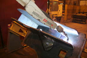
with a competitive advantage by providing better weld quality
and greater productivity compared to a semi-automatic
welding process.The Benefits of Automated Welding
The Best Applications for Automated Welding
Process Flow is Important
Quality Matters
Shift in Skill Set
The Next Step
Consumables for Robotic Welding
How to Choose Robotic Welding Consumables
What you should know to improve performance and reduce costs
Mind Your Extensions and Connections
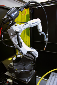
of an automated welding system, but they
can have a measurable impact on
downtime and day-to-day costs. Be
certain to carefully select and maintain
them to get the best performance
and minimize downtime.The Impact of Welding Wires on Contact Tip Selection
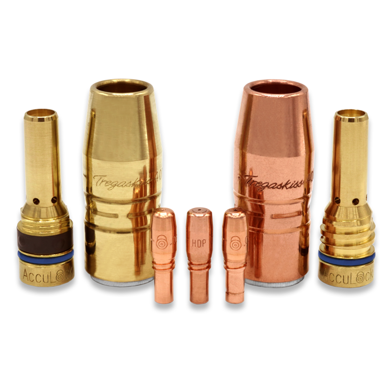
What is Your Mode of Welding?
Selecting the Right Nozzle … and Maintaining It
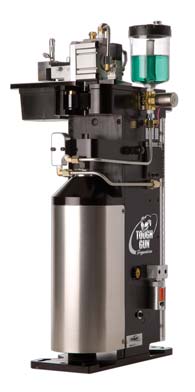
and contact tips.Other Considerations
Is Poor Conductivity Impeding Your Welding Performance
Is Poor Conductivity Impeding Your Welding Performance?
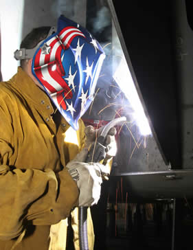
Accurate Troubleshooting
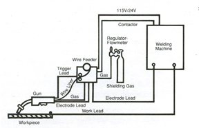
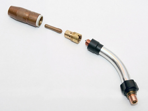
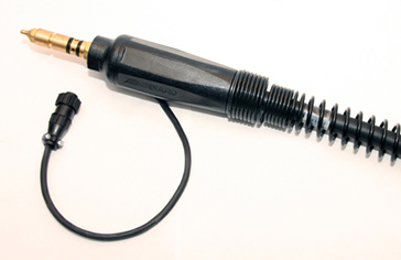
The Basics: MIG Troubleshooting
The Basics: MIG Troubleshooting
Keep Covered
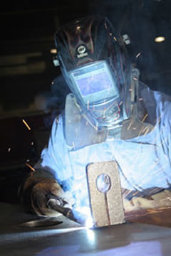
Don’t Be Undercut
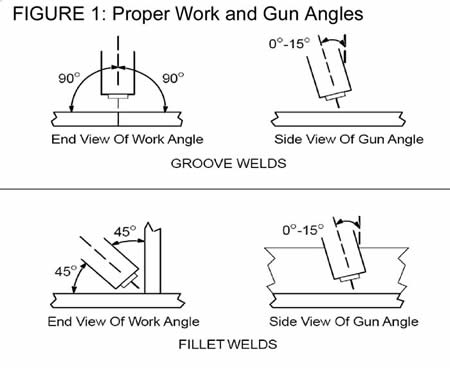
Keep Track of the Heat
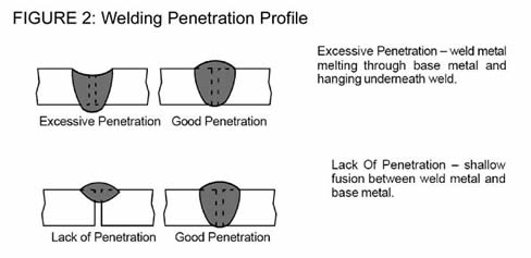
All About Wire
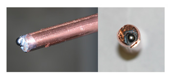
No Cure-All
Related Articles
Detroit-Area Company Increases Productivity and Supports Lean Initiatives with New Robotic MIG Gun
Detroit-Area Company Increases Productivity and Supports Lean Initiatives with New Robotic MIG Gun
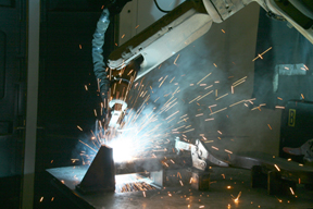
has helped Watson minimize downtime for neck
changeover, and it offers the welding capacity to weld
on a variety of parts and part thicknesses.Time to Fix What’s Broken
Durability, Flexibility and Accuracy
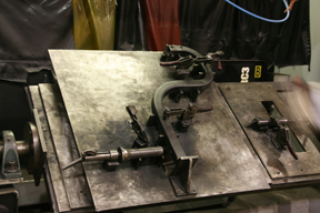
creates the tooling necessary to weld all
its components successfully.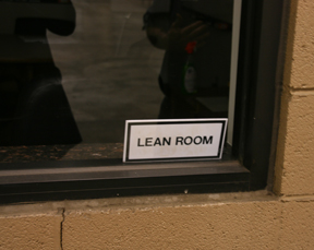
Watson, the company is “serious about lean” — so
much so that they have a dedicated workforce for it.Ownership and Inventory Made Easy
components, along with products for the automotive and
commercial industries — all of which are carefully and neatly organized on shelves and in bins for maximum efficiency.Lean and Productive
Strong Bond and Strong Community at San Diego Continuing Education
Strong Bond and Strong Community at San Diego Continuing Education
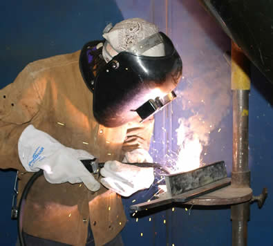
Partnering for Success
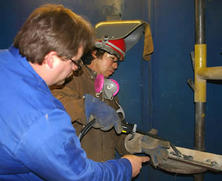
Reaching out to the Community
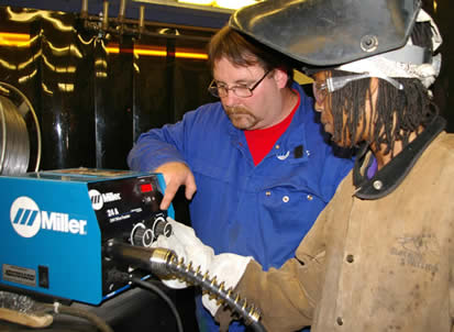
Air-Cooled vs. Water-Cooled MIG Gun: Which is Right for You
Air-Cooled vs. Water-Cooled MIG Gun: Which is Right for You?
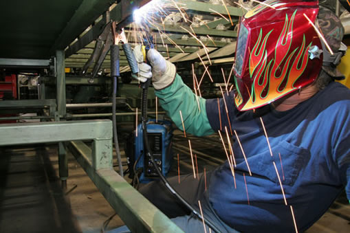
First Things First
Amperage Requirements
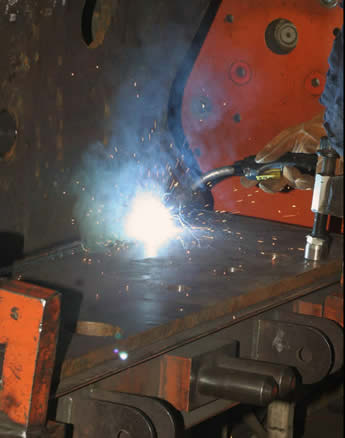
Duty Cycle
Gun Weight and Operator Comfort
Worksite Location
Cost
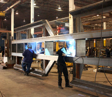
Conclusion
Thoughts for Improving Welding Operations in Today’s Automotive Industry
From Technology to Technical Support:
Thoughts for Improving Welding Operations in Today’s Automotive Industry
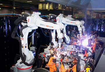
into the welding process can help ensure the necessary uptime
for automotive applications.Equipment Standardization
Single Arc Pulsed Technology
Streamline Vendors
Error Proofing
Best Practice Meetings
Preventive Maintenance
Coopetition
Built-in Buffers
Addressing Welding Challenges in Today’s Automotive Industry
Addressing Welding Challenges in Today’s Automotive Industry
Well-Managed Inventory Equals Greater Uptime
of best practices can help automotive companies “do more with less.”The Right Equipment Maintained Properly
Meeting the Demands
Is it Time to Automate? 5 Factors to Consider
Is it Time to Automate?
5 Five Factors to Consider
Factor #1: Plan Accordingly
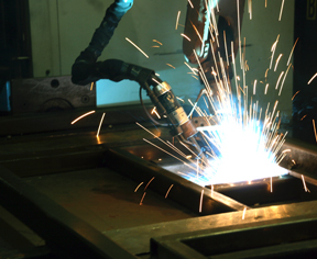
and creating a detailed plan is key to gaining the many
advantages of an automated welding system.Factor #2: Evaluate Your Application
Factor #3: Assess Your Facility
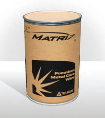
cost of purchasing larger wire packages and the
appropriate storage areas for them.Factor #4: Determine Your Available Personnel and Training
Factor #5: Justify the Expense
Final Thoughts
Handrails in Hell, Arizona
Handrails in Hell: Hot Az Hell Welding and Fabrication Puts Dura-Flux to the Test
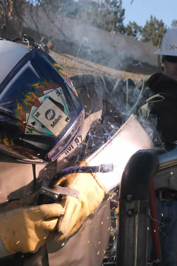
The key to success
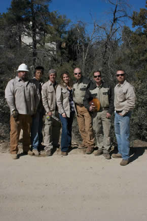
Everyone at Hot Az Hell Welding and Fabrication can perform multiple jobs, one of the secrets to their rapid growth and success since being founded in 2006.Focus on efficiency
Reliable equipment equals increased productivity
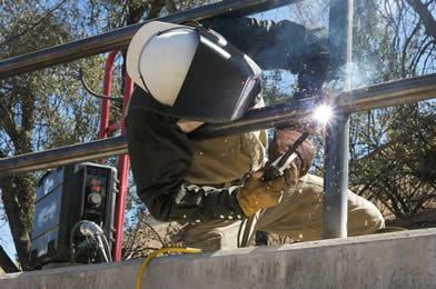
The Dura-Flux recently allowed Hot Az Hell Welding and Fabrication to install 200 linear feet of three-rail hand rails with only a single tip change – which was attributed to operator error.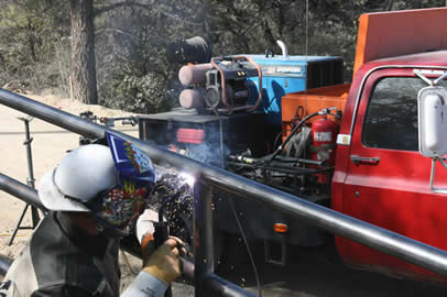
Avoid These 5 MIG Gun Myths to Optimize Performance
Avoid These 5 MIG Gun Myths to Optimize Performance
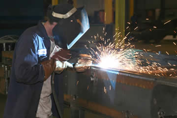
Myth #1 — MIG guns are all the same, so price should be the deciding factor when purchasing a new gun.
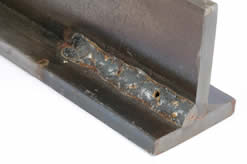
Myth #2 — Consumables aren’t very important to weld quality and performance.
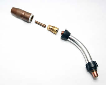
Myth #3 — Preventative gun and consumables maintenance is a waste of valuable time that could be better spent in production.
Myth #4 — It’s always better to err on the safe side and overmatch the gun amperage to the application.
Myth #5 — The MIG gun liner does not have a significant impact on welding performance.
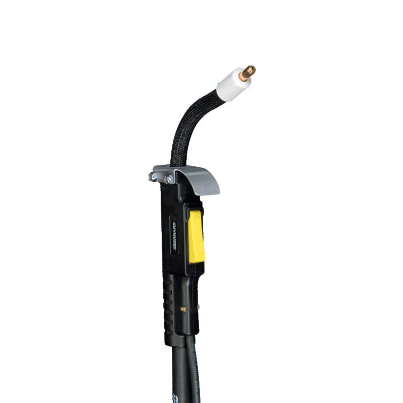
MIG Welding Shielding Gas Basics
MIG Welding Shielding Gas Basics
Choosing The Right Shielding Gas
of the weld bead, can be caused by inadequate shielding gas and can dramatically weaken
the weld. Carbon Dioxide (CO2)
Argon
Oxygen
Helium
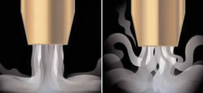
in shielding gas coverage. The photo on the left shows good coverage, while the coverage in the photo on the right allows
the air environment contaminate the shielding gas.Getting the Shielding Gas to the Weld Pool
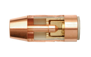
contact tip is seated in the diffuser and held in place
by the spatter guard inside the nozzle.Don’t Let Consumables Consume Your Profits
Don’t Let Consumables Consume Your Profits: Choose, Use and Troubleshoot Wisely
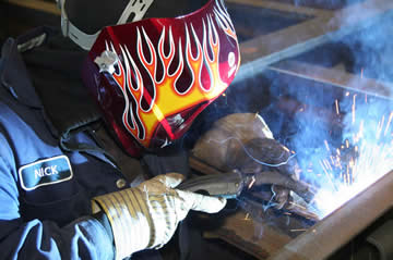
Choose Wisely
Use Wisely
Troubleshoot Wisely
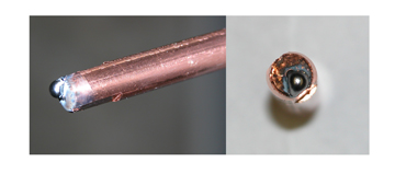
Contractor increases productivity…
Jolson Welding Improves Productivity with New MIG, FCAW Equipment
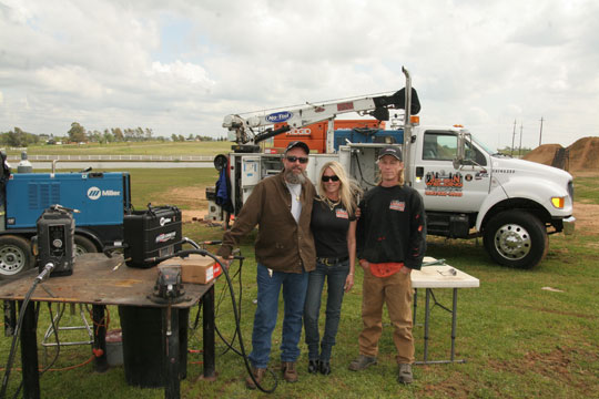
Making the Change
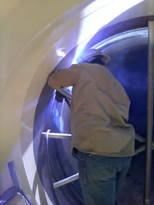
The result of the testing
The New Approach to Self-Shielded Welding
Gaining the Most Out of Gas-Shielded Welding
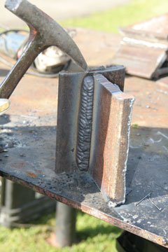
Tips For Avoiding Common Flux-Cored Problems & Improving Your FCAW Welds
Tips For Avoiding Common Flux-Cored Problems & Improving Your FCAW Welds
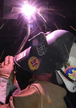
Tip One: Avoid Wire Feeding Problems
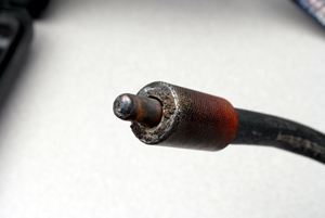
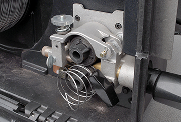
Tip Two: Stop Porosity and Worm Tracking
Tip Three: Eliminate Slag Inclusions
![]()
![]()
Tip Four: Prevent Undercutting and Lack of Fusion
Tip Five: Avoid Excessive Penetration or Lack of Penetration
Final Tips
Related Articles
Finding a MIG Gun That Fits
Finding a MIG Gun That Fits: Stay Cool and Comfortable While Welding
Selecting the Right Amperage
Getting a Handle On the Selection
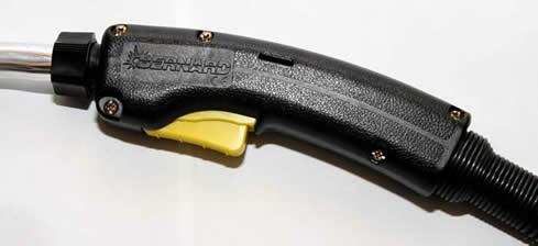
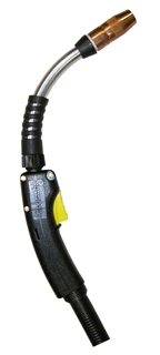
Staying Cool
Putting It All Together
Choosing Wisely Simple Ways to Save Money and Reduce Downtime
Choosing Wisely: Simple Ways to Save Money and Reduce Downtime by Selecting the Right MIG Gun Consumables

Line Up for the Best Performance
Tips for Making the Right Contact
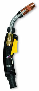
Know Your Nozzles
Your FAQs About FCAW…
Your FAQs About FCAW-SS Problems Answered
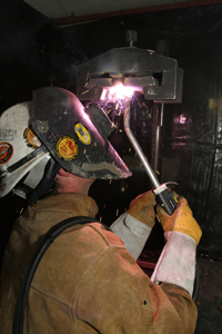
What are slag inclusions and how can I prevent them?
How can I prevent burnbacks?
Why does lack of fusion occur?
What are the causes of and solutions for bird-nesting?
What can I do to ensure I get the best joint penetration?
What can I do to prevent porosity?
More FAQs?
Maintaining Your MIG Gun… and Your Welding Costs
Maintaining Your MIG Gun… and Your Welding Costs
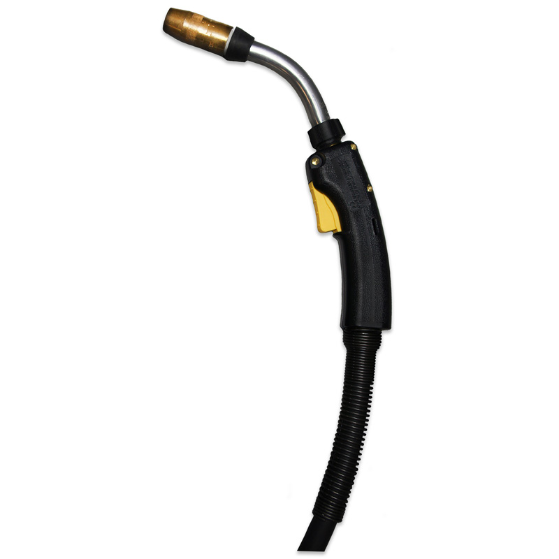
We all have the tendency to fall victim to the “bigger is better” philosophy. When it comes to purchasing a MIG gun, however, that thinking may cost you more money than is necessary for this equipment. It can also lead to costly downtime.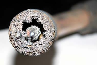
Regularly inspecting your MIG gun can be an important part of reducing costs and gaining good welding performance. Fortunately, preventive maintenance (PM) for a MIG gun doesn’t have to be time consuming or difficult. Consider these key factors.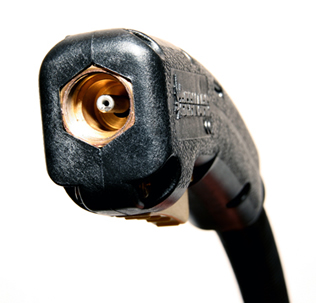
missing screws. Check that your MIG gun trigger is not sticking or otherwise malfunctioning. Replace these components as necessary.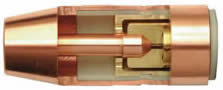
The Causes of GMAW Flaws
The Causes of GMAW Flaws … and the Cures to Help Welding Operators Get Back to Work Faster
Porosity
or the GMAW gun are free of leaks can help solve the problem.Burn Through
Incomplete Joint Penetration (Lack of Penetration)
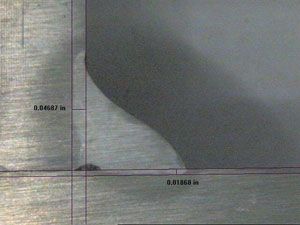
Undercutting
Hot Cracking
Incomplete Fusion
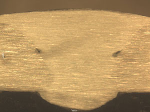
When the weld metal fails to completely fuse with the base metal or with the preceding weld bead in multi-pass applications, incomplete fusion can occur. Some people also refer to this weld flaw as cold lap or lack of fusion.10 Mistakes in Running a Welding Operation and How to Fix Them
10 Mistakes in Running a Welding Operation and How to Fix Them
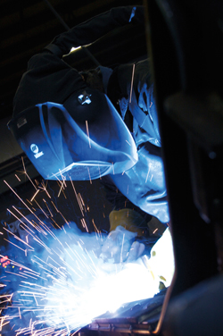
Mistake No. 1: Improper Filler Metal Storage and Handling
Mistake No. 2: Repurposing Old Equipment
Mistake No. 3: Using the Wrong Size MIG Gun
Mistake No. 4: Improper Preheat or Interpass Temperature Control
weld procedure altogether. Yet preheating is one of the biggest deterrents against cracking, as it slows down the cooling rate after welding. The type and thickness of the material being welded will determine preheat and interpass temperature. These requirements can be found in the application’s welding procedure, welding codes or other fabrication documents. For the best results, welding operators need to preheat the material completely through and extend the heated area to approximately three inches on either side of the weld joint. Welding should commence while the material is at or above the preheat temperature. Allowing the weldment to cool below the required interpass temperature may also lead to cracking.Mistake No. 5: Ignoring Preventive Maintenance
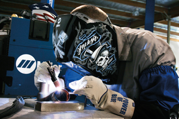
Mistake No. 6: Shielding Gas Inconsistencies
Mistake No. 7: Purchasing Filler Metals Based on Cost Only
Mistake No. 8: Improper Weld Preparation
Mistake No. 9: Disregarding MIG Gun Consumables
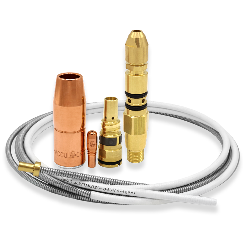
Mistake No. 10: Overlooking Training Opportunities
Keeping an Open Mind and Reaping the Benefits
Keeping an Open Mind and Reaping the Benefits: How One Company Reduced its Downtime and Costs Through a Simple Product Trial
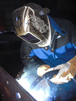
The Projects and Challenges
The First Solution
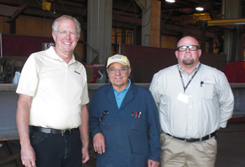
Finding Additional Benefits with New MIG Guns
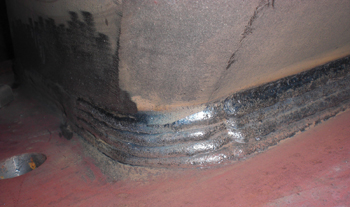
Reaping the Benefits
![]()
![]()