
Is Poor Conductivity Impeding Your Welding Performance?
Most people understand that the electrical circuit is at the heart of the welding operation. What you might not be aware of, however, is how easy it is for disruptions in this circuit to interfere with productivity, weld quality and equipment service life.
All of these factors are ultimately affected by conductivity: the ability of the electrical current to flow along the welding circuit. Conductivity can also be referred to through its inverse: resistance, or the interference of electricity to flow freely along the circuit. If the electrical current moves with very little resistance, the material is very conductive. Gold, for example, is one of the most conductive materials on earth (which is why it was used in early telephones and other electrical equipment), but its cost prevents its use in welding equipment.
Copper, aluminum and other metals are used in welding equipment because they strike a good balance between cost and conductivity. The copper used in welding equipment does a good job allowing the electrical current to flow. There is still a very small amount of resistance inherent in the properties of the material, but it is not enough to interfere with the welding operation. Excessive resistance along the circuit, however, can cause weld defects, reduce productivity and lead to premature equipment failure.
To understand exactly how conductivity impacts almost every aspect of your welding operation, it helps to think about the welding circuit like a garden hose. The water flowing through the hose is analogous to the electrical current in the circuit. If you squeeze the hose in one spot, it reduces the amount of water that is able to flow from the hose. Likewise, an area of electrical resistance, such as a worn out or dirty power pin connection, restricts electrical flow along the entire length of the circuit
When resistance prevents the electrons from continuing along the circuit, they convert their energy to heat, which is absorbed by the surrounding components. Heat causes plastic and metal components to expand and to contract when cooled, creating mechanical stress that can lead to premature equipment failure.
Interestingly, heat itself is a source of resistance, which is why high heat welding processes, such as with metal-cored wire, demand that the contact tip be recessed as far from the welding arc as practicable. As the contact tip absorbs the heat from the arc, it loses its ability to transfer the current to the wire, resulting in increasingly poor welding performance.
Excessive resistance anywhere along the circuit can result in a wide range of problems, including a sputtering or erratic arc, inconsistent weld appearance and frequent contact tip burn-back. These problems occur because resistance in the circuit reduces the amount of current that can flow to the welding arc. When the power source senses the reduced current at the arc, it sends a surge of voltage in order to overcome the restricted current flow. This increased voltage causes the popping and sputtering that leads to poor and inconsistent weld quality.
Accurate Troubleshooting
Being able to correctly identify and troubleshoot excessive electrical resistance is critical to reducing the equipment and rework costs.
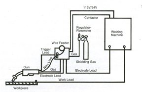
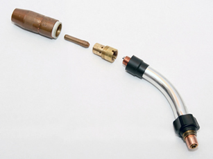
The mechanical connections between the welding components account for most interruptions in conductivity. These include: the connection between the power source and the gun’s power cable plug; the fittings and connections between the gun’s power cable, neck, diffuser, contact tip and welding wire; and the connections between the work lead, welding table and power source. Routinely check these connections before problems arise in order to avoid compounded problems down the road.
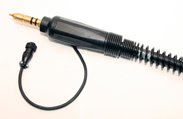
There are three main types of power cable terminations: compression, set screw and crimped. Compression fittings typically provide the best combination of durability and reparability. Set screw fittings are easily repaired, but often come loose and require frequent tightening. Crimped fittings provide good contact between the cable and gun, but are also susceptible to overheating and gradual degradation. Loose cable, gun and power source connections should be tightened to manufacturer specifications or replaced if damaged.
Because the welding wire wears the bore over time, the contact tip should be one of the first areas checked during troubleshooting. A contact tip that doesn’t maintain constant connection to the welding wire should be replaced, regardless of whether it is the primary source of the conductivity problem.
Paint and other surface contaminants can reduce the conductivity of the work lead connection. To ensure maximum electrical flow, attach the work lead clamp to clean, unpainted metal and as close to the weld joint as possible. If using rotating work leads, such as turntables and positioners, conductive grease can help increase the conductive surface area between the moving and non-moving parts.
The other most frequent source of interruptions in conductivity is frayed copper stranding within the gun or, less frequently, in the work lead cables. These strands can fray and break due to repeated bending and twisting, particularly on guns that don’t contain strain relief components at the connection points with the gun and power source. Also, thermal stresses can cause the copper stranding to become brittle, increasing the likelihood of fatigue failure.
For this reason, the gun cable should only be bent or twisted if absolutely necessary. The resistive heat caused by frayed cable stranding, in addition to causing poor weld performance, can also accelerate the degradation of the remaining intact strands and cause the eventual failure of the cable.
Unfortunately, it is difficult and often impractical to inspect the cable for damage as a preventative measure. Check the mechanical connections and fittings first if poor conductivity is the suspected source of a welding problem, and then proceed to check the condition of the cable.
It may be possible to cut and re-terminate the cable if the damage occurs near the connections to the power source or gun. Severe cable damage or damage near the middle of the cable may require replacement of the cable or the entire gun.
Welding technology has advanced substantially since the days of DC ‘buzz boxes,’ but one thing that has remained constant throughout the decades is the need to establish and maintain a robust electrical circuit. Resistance from loose fittings and connections will occur as a natural part of the wear and tear that welding equipment undergoes during normal use. However, knowing the common signs of poor conductivity and following a regular inspection routine will help ensure that built-up resistance doesn’t cause undue equipment and rework costs.