Is Poor Conductivity Impeding Your Welding Performance?
Most people understand that the electrical circuit is at the heart of the welding operation. What you might not be aware of, however, is how easy it is for disruptions in this circuit to interfere with productivity, weld quality and equipment service life.
All of these factors are ultimately affected by conductivity: the ability of the electrical current to flow along the welding circuit. Conductivity can also be referred to through its inverse: resistance, or the interference of electricity to flow freely along the circuit. If the electrical current moves with very little resistance, the material is very conductive. Gold, for example, is one of the most conductive materials on earth (which is why it was used in early telephones and other electrical equipment), but its cost prevents its use in welding equipment.
Copper, aluminum and other metals are used in welding equipment because they strike a good balance between cost and conductivity. The copper used in welding equipment does a good job allowing the electrical current to flow. There is still a very small amount of resistance inherent in the properties of the material, but it is not enough to interfere with the welding operation. Excessive resistance along the circuit, however, can cause weld defects, reduce productivity and lead to premature equipment failure.
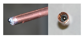
To understand exactly how conductivity impacts almost every aspect of your welding operation, it helps to think about the welding circuit like a garden hose. The water flowing through the hose is analogous to the electrical current in the circuit. If you squeeze the hose in one spot, it reduces the amount of water that is able to flow from the hose. Likewise, an area of electrical resistance, such as a worn out or dirty power pin connection, restricts electrical flow along the entire length of the circuit
When resistance prevents the electrons from continuing along the circuit, they convert their energy to heat, which is absorbed by the surrounding components. Heat causes plastic and metal components to expand and to contract when cooled, creating mechanical stress that can lead to premature equipment failure.
Interestingly, heat itself is a source of resistance, which is why high heat welding processes, such as with metal-cored wire, demand that the contact tip be recessed as far from the welding arc as practicable. As the contact tip absorbs the heat from the arc, it loses its ability to transfer the current to the wire, resulting in increasingly poor welding performance.
Excessive resistance anywhere along the circuit can result in a wide range of problems, including a sputtering or erratic arc, inconsistent weld appearance and frequent contact tip burn-back. These problems occur because resistance in the circuit reduces the amount of current that can flow to the welding arc. When the power source senses the reduced current at the arc, it sends a surge of voltage in order to overcome the restricted current flow. This increased voltage causes the popping and sputtering that leads to poor and inconsistent weld quality.
Accurate Troubleshooting
Being able to correctly identify and troubleshoot excessive electrical resistance is critical to reducing the equipment and rework costs.
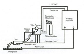
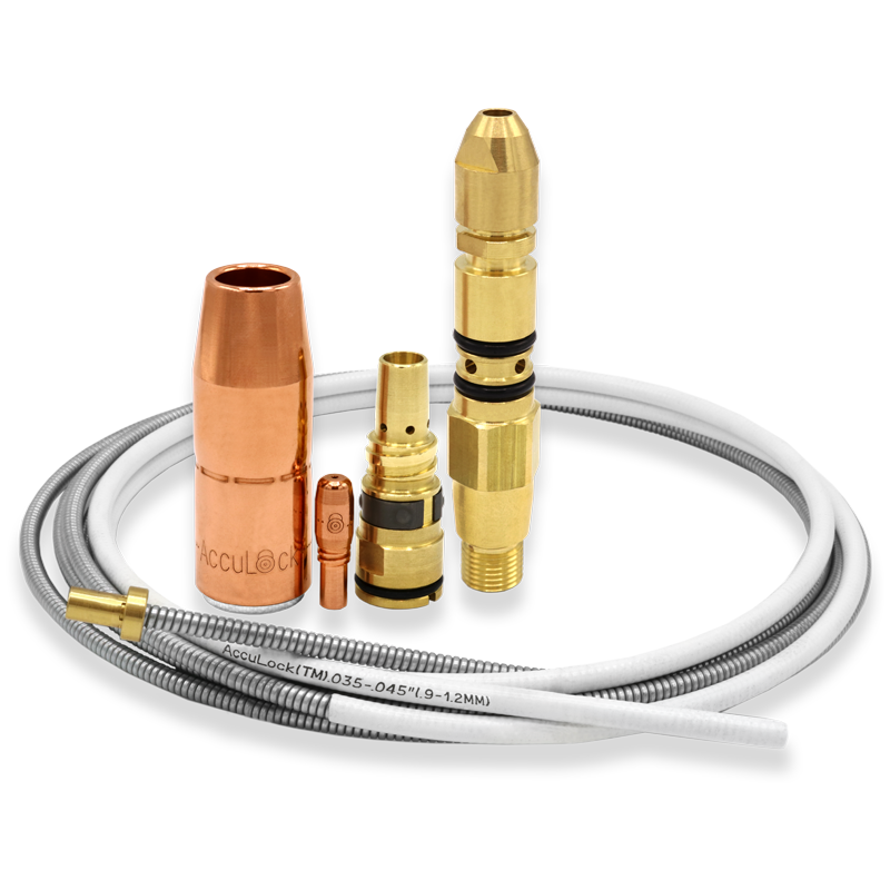
The mechanical connections between the welding components account for most interruptions in conductivity. These include: the connection between the power source and the gun’s power cable plug; the fittings and connections between the gun’s power cable, neck, diffuser, contact tip and welding wire; and the connections between the work lead, welding table and power source. Routinely check these connections before problems arise in order to avoid compounded problems down the road.
There are three main types of power cable terminations: compression, set screw and crimped. Compression fittings typically provide the best combination of durability and reparability. Set screw fittings are easily repaired, but often come loose and require frequent tightening. Crimped fittings provide good contact between the cable and gun, but are also susceptible to overheating and gradual degradation. Loose cable, gun and power source connections should be tightened to manufacturer specifications or replaced if damaged.
Because the welding wire wears the bore over time, the contact tip should be one of the first areas checked during troubleshooting. A contact tip that doesn’t maintain constant connection to the welding wire should be replaced, regardless of whether it is the primary source of the conductivity problem.
Paint and other surface contaminants can reduce the conductivity of the work lead connection. To ensure maximum electrical flow, attach the work lead clamp to clean, unpainted metal and as close to the weld joint as possible. If using rotating work leads, such as turntables and positioners, conductive grease can help increase the conductive surface area between the moving and non-moving parts.
The other most frequent source of interruptions in conductivity is frayed copper stranding within the gun or, less frequently, in the work lead cables. These strands can fray and break due to repeated bending and twisting, particularly on guns that don’t contain strain relief components at the connection points with the gun and power source. Also, thermal stresses can cause the copper stranding to become brittle, increasing the likelihood of fatigue failure.
For this reason, the gun cable should only be bent or twisted if absolutely necessary. The resistive heat caused by frayed cable stranding, in addition to causing poor weld performance, can also accelerate the degradation of the remaining intact strands and cause the eventual failure of the cable.
Unfortunately, it is difficult and often impractical to inspect the cable for damage as a preventative measure. Check the mechanical connections and fittings first if poor conductivity is the suspected source of a welding problem, and then proceed to check the condition of the cable.
It may be possible to cut and re-terminate the cable if the damage occurs near the connections to the power source or gun. Severe cable damage or damage near the middle of the cable may require replacement of the cable or the entire gun.
Welding technology has advanced substantially since the days of DC ‘buzz boxes,’ but one thing that has remained constant throughout the decades is the need to establish and maintain a robust electrical circuit. Resistance from loose fittings and connections will occur as a natural part of the wear and tear that welding equipment undergoes during normal use. However, knowing the common signs of poor conductivity and following a regular inspection routine will help ensure that built-up resistance doesn’t cause undue equipment and rework costs.
Like any welding process, MIG welding has its complications. Even so, there is no reason to let common problems slow you down. With a bit of knowledge and some solid troubleshooting skills, you can easily find the right solution to get back to welding—sooner than later. Consider the following guidelines to help you along the way. Porosity occurs when a gas pocket becomes caught in the weld metal. This discontinuity can appear at any specific point on the weld or along its full length, and/or on the surface or the inside of a weld. The result, regardless of the location, is always the same: a weaker weld. Inadequate shielding gas coverage is one of the most common causes of porosity. To correct this problem, first check the regulator or flow meter for adequate gas flow, increasing it if necessary, and check the gas hoses and the gun for leaks. Whether welding inside or outside, shield the arc and weld puddle from drafts with a welding screen. Next, confirm that the MIG gun nozzle is large enough for the application, as too small of a nozzle can prevent proper shielding gas flow. Keep the nozzle one-fourth to one-half inch away from the work piece, make certain it is free of spatter, and always use the correct contact tip recess. Slow your travel speed and hold the MIG gun near the bead at the end of the weld until the molten metal solidifies; pulling the gun away too soon can interrupt gas coverage and leave the setting weld vulnerable to the atmosphere. Additional causes of porosity include: using the wrong gas (always use a welding-grade shielding gas appropriate for the base metal and filler metal), using too much or the wrong type of anti-spatter (use the correct amount and type for your application) and extending the welding wire too far out of the nozzle (extend no more than one-half inch beyond the nozzle). Impurities in the base metal, such as sulfur and phosphorous in steel, or a dirty base metal can be further causes of porosity. If specifications allow, consider changing to a different composition of base metal, and always remove rust, grease, paint, coatings, oil, moisture and dirt prior to welding. Filler metals with added deoxidizers can help to “clean” the weld, but should never be solely relied upon to minimize porosity. Finally, replace any wet or contaminated shielding cylinders immediately. Undercutting occurs when a groove melts into the base metal next to the toe of the weld and the weld metal fails to fill that area. This discontinuity weakens the toe of the weld, increasing the chances of cracking. Correcting the problem is relatively simple: reduce the welding current, decrease the welding arc voltage and adjust your MIG gun angle toward the joint. Reduce your travel speed so the weld metal completely fills the melted-out areas of the base metal. When using a weaving technique, pause slightly at each side of the weld bead. When the weld metal fails to completely fuse the weld metal with the base metal or with the preceding weld bead in multi-pass applications, incomplete fusion can occur. Some people refer to this problem as lack of fusion. Generally, an incorrect MIG gun angle is the cause and you should adjust it accordingly. Follow these steps: If correcting the MIG gun angle does not remedy incomplete fusion, look to see if the welding puddle is too far ahead of the wire. If so, increase your travel speed and/or the welding current to correct the problem. Conversely, if you suspect insufficient heat input has caused incomplete fusion, select a higher voltage range and/or adjust the wire feed speed as necessary. Finally, always clean the surface of the base metal prior to welding to remove contaminants that may prevent the metal from fusing together. Another common MIG welding problem—spatter—occurs when the weld puddle expels molten metal and scatters it along the weld bead; this molten metal then cools and forms a solid mass on the workpiece. Excessive spatter not only creates a poor weld appearance, but it can also lead to incomplete fusion in multiple welding pass applications. Too fast of a wire feed speed, too high of a voltage setting, and too long of a welding wire extension, or stick-out, can cause spatter. Lowering the given settings and using a shorter stick-out can help. Like porosity, insufficient shielding gas and/or dirty base materials can cause spatter. As necessary, increase the shielding gas flow at the regulator and minimize drafts near the welding arc, clean and dry the welding wire, and remove all grease, dirt and other contaminants from the base metal. Other factors that can cause spatter are: the wrong size contact tip, a worn contact tip or the wrong tip to nozzle recess. Be certain you have the right contact tips, nozzles and recess parameters for the application. Excessive penetration occurs when the weld metal melts through the base metal and hangs underneath the weld. Excessive heat input is usually to blame for the problem. To correct this, select a lower voltage range, reduce the wire feed speed and increase your travel speed. Conversely, insufficient heat input can cause lack of penetration, or the shallow fusion between the weld metal and the base metal. Selecting higher wire feed speed, a higher voltage range and/or reducing travel speed are all viable remedies. Preparing the joint correctly also helps prevent lack of penetration—the preparation and design should permit access to the bottom of the groove and allow you to maintain proper stick-out and arc characteristics. Wire feed stoppages and wire feed system malfunctions can adversely affect the welding arc and create irregularities that may weaken the weld bead. Birdnesting, a tangle of wire that halts the wire from being fed, is a common problem. You can resolve birdnesting by flipping up the drive roll and pulling the wire back out of the gun. Next, trim the affected wire and re-thread it through the feeder and back to the gun. If the welding specifications allow, decrease the drive roll tension, use a larger diameter wire and/or reduce the distance the wire feeds (use shorter cables) to minimize the chance of birdnesting. Burnback is also very common. It results when a weld forms in the contact tip, and usually occurs because of too slow of wire feed speeds and/or from holding the MIG gun too close to the base metal during welding. To correct burnback, increase the wire feed speed and lengthen the distance of the MIG gun from the workpiece (the nozzle should be no further than one-half inch from the metal). Replace burnback-damaged contact tips by removing the nozzle and the contact tip (which may be melted to the wire), snipping the wire, installing the new contact tip and replacing the nozzle with one that has the appropriate tip recess for the application. Other causes of wire feeding problems include liner blockages, improperly trimmed liners (too short/burred/pinched) or the wrong size liner. To remedy these problems, replace any liner if you find a blockage, always trim the liner according to the manufacturer’s direction and be certain you are using the correct size liner for the welding wire diameter. Remember, quality MIG welds are the result of not only good welding technique, but also your ability to identify and solve problems quickly if they do occur. Continue arming yourself with some basic information and you’ll be able to tackle the most common problems associated with MIG welding without sacrificing time or quality.
Worldwide, companies serving the automotive industry have faced a unique set of challenges in the last several years. Still, as the economy begins to rebound, each must find ways to maintain their productivity and profitability — often with fewer employees than before the recent recession. A large part of maintaining that productivity is to ensure high levels of uptime in the robotic welding operations. Conventional problems like spatter, burn-through and poor part fit-up often hinder such attempts, as do issues like managing large amounts of inventory and contending with downtime to service welding equipment. Unfortunately, there is no single answer to these challenges. There are, however, some considerations that may help reduce suppliers’ pains and assist in other interrelated parts of the process. The recent increase in demand for production is causing some automotive suppliers, especially those in North America, to make capital investments that they previously postponed during the recession. When possible, standardizing on a single brand and style of welding power source, robotic controller, and GMAW gun and consumables during this investment can streamline inventory and maintenance procedures. For companies in organic growth mode with new programs and/or Greenfield operations, this standardization can help in long-term equipment re-deployment to other facilities, as well as streamline the manpower learning requirements. For companies that are in acquisition mode, however, this standardization may not be feasible. Instead, these suppliers should, at a minimum, consider standardizing on a single brand and style of robotic GMAW guns and consumables to minimize inventory. Doing so can also reduce the risk of improper consumable installation, which can lead to unscheduled downtime to rectify. Many automotive suppliers rely on tandem welding processes as a means to generate greater productivity. In recent years, however, advancements in single arc pulsed technology have proven very efficient in providing faster travel speeds and minimizing spatter. This technology, which effectively lowers the average amperage level during welding (by regularly switching the current between high peak amperages and low background amperages), is also quite easy to operate. Given the reduction in workforce in the automotive industry, combined with an overall shortage of skilled welders, this less complex (but highly efficient) technology has already proven beneficial for many automotive suppliers. Automotive suppliers, particularly those with multiple locations, may want to consider purchasing their robotic GMAW guns, peripherals and consumables from a single source vendor or welding distributor. Having multiple vendors may appear to provide cost savings up front; however, a per-item approach can actually increase the total spend. Instead, by single sourcing a product line, a company is better poised to maximize their purchasing power with one vendor and gain loyalty discounts. The vendor may also be more inclined to aid in new efficiencies and technologies. Plus, a trusted single source vendor can often help automotive suppliers assess their total consumable and robotic GMAW gun usage, streamline inventory and reduce costly paperwork at the same time. In addition to standardizing equipment when possible, using welding products that minimize the opportunity for errors is an important part of keeping the welding process flowing and reducing operator error. For example, nozzle detection (i.e. that doesn’t increase cycle time) can eliminate the potential of excessive rework or scrap. Avoiding errors in equipment installation is also critical, as missing or incorrectly installed components on the front end of a robotic MIG gun can cause them to become electrically alive, causing premature failure and poor welding performance. When possible, suppliers in the automotive industry should work with equipment manufacturers and vendors or welding distributors who can engage regularly in best practice meetings. These meetings can occur by conference call or in person, and can help determine what practices in the welding operation are working most effectively and what areas need improvement. Open issues can be prioritized amongst a group for time-phased solutions. These meetings can especially help companies with multiple locations, even globally, to identify opportunities for changes that could positively affect other facilities. They are also an excellent platform for brainstorming error-proofing ideas and serve to open communication among the parties involved in the success of a company’s welding operation. Even though preventive maintenance or PM may have become a commonplace buzzword in recent years, the fundamentals are still critical to providing good welding performance and reducing unscheduled downtime in the automotive industry. Companies should always take care to inspect connections in the GMAW gun, wire feeder, consumable and ground cables on a regular basis. Replacing worn components during scheduled downtime (at the beginning of a shift, for example) can help prevent problems during production. As of yet, “predictive maintenance” —– technology that alerts when consumables need to be changed – is not available. In the meantime, however, companies can instead track contact tip usage to gain an understanding of how often these components need to be replaced. Non-subjective analytical processes should be used to benchmark component longevity and performance. During Best Practice meetings, “Coopetition” can be an integral part of maintaining an effective welding operation for the greater good of the customer. This term refers, in short, to cooperation that occurs between competitive equipment manufacturers. The reality of any welding operation is that the manufacturer of the robotic GMAW gun or welding wire may be in direct competition with the company whose power sources are in an automotive supplier’s weld cell. Even so, finding equipment manufacturers who are willing to work together to address problems in the welding operation is key to resolving issues when they arise. A problem with the contact tip, for example, is usually a “barometer” of other things happening in the process. In short, it is very often a symptom of a problem, as opposed to the root cause. Having partners who are willing to put aside competitive differences for the good of resolving problems like these is important to gaining good welding performance. As is typical in automotive “just-in-time” applications, suppliers want to reduce instances of work-in-progress (WIP) and keep parts flowing (Takt time). To continue that work flow but still allow for any instances of stoppage in a robotic welding cell, suppliers may consider building a buffer into production. For example, if a company has a production line of 40 welding robots, breaking that line into fifths (five sections of eight robots), allows them to address any instances of consumable failure while causing a stoppage of only eight robots instead of shutting down production on all 40. That buffer can mean a significant difference in terms of lost production and money. And while no single one of these considerations can ensure the levels of productivity and profitability to which automotive suppliers strive as production demands increase, they can be a step in the right direction. Automotive suppliers should consider working with a trusted welding equipment manufacturer and vendor to discuss a plan for assessing their robotic welding operation and identifying opportunities for improvement.
The automotive industry has certainly begun to show signs of rebounding from the economic downturn; however, companies are now being asked to “do more with less” as production volumes approach the levels of several years ago. More than ever, companies require operational efficiencies to maintain process flow and avoid unscheduled downtime of automated equipment. Commonly, arc-welding process challenges have a significant impact on achieving production goals and maintaining efficiency. Typical contributors to arc-welding process inefficiencies include poor part fit-up, tool center point (TCP) repeatability, spatter and managing consumable changes. Effectively managing these elements are essential if companies are to meet their quality requirements and fulfill a high-volume production demand. As the automotive industry continues experience an upswing in production—up 12.16 percent year-over-year through March 19, 2011 (Automotive News)— maintaining an effective and efficient operation will become even more challenging. Reductions in the workforce over the last several years have left the industry with fewer employees to monitor welding operations and the overall shortage of skilled welders has compounded the challenge. Whereas 10 years ago a large automotive supplier may have had one welding technician for 20 robots, today that ratio has increased to as few as one welding technician for every 50 robots – or more. Clearly, the lack of resources creates challenges but eliminating non-value-added activity (or that which doesn’t contribute directly to throughput) can help overcome those. Practices such as equipment standardization, preventive maintenance and product selection can promote a Leaner operation and provide opportunities to improve process flow and operational efficiency. In recent years, the consolidation of automotive suppliers and facilities has resulted in welding operations made up of multiple styles and brands of welding equipment, including power sources, robotic controllers, robotic manipulators and GMAW guns. The outcome is often a wide breadth of products to manage and, with fewer resources, an increased potential for costly errors and unscheduled downtime. Not surprisingly, in an industry that requires repeatable, high-volume welds—some up to 500 parts in a single shift—consistency is critical and any deviation in quality could result in downtime, scrap or rework. Ideally, standardizing on a single GMAW gun brand can help companies in the automotive industry avoid unscheduled downtime for changing out incorrect consumables or reworking quality issues. It can also reduce the amount of time spent managing inventory and provide a built-in poka yoke (mistake-proofing) system by eliminating (or significantly reducing) the opportunities for incorrect installation. Some companies have found that such standardization, along with a vendor-managed consumable system works well and contributes positively to their goal of maintaining process efficiency and equipment utilization. The process of standardization may take time—replacing older GMAW guns as they wear, for example—but in the long term it can yield positive results in quality, performance and cost. It also allows the production team to have one point of contact for technical support should questions arise about the performance of a GMAW gun or consumable, as opposed to having to contact multiple manufacturers. To help with the transition to one GMAW equipment supplier, front-end conversion kits are widely available and allow companies to standardize on a single brand of consumables, regardless of the type of GMAW gun being used. These kits are a good alternative to replacing an entire fleet of GMAW guns, while still offering the benefits of standardized inventory. In some cases, there is an opportunity to maximize the value of welding consumables by using the same contact tips and nozzles for semi-automatic applications (such as those for repairs or rework) after they are too worn for the robotic application, which further reduces inventory. Most welding technicians, supervisors or operators in the automotive industry will attest to the fact that proper part fit-up is a constant concern. But not only do the parts that move into the weld cell need to be of the proper dimension and fit, the GMAW welding gun and consumables being used also need to provide accurate, repeatable and durable performance. Robotic GMAW guns are intended to weld at the same location every cycle by providing a consistent tool center point (TCP). Some products are more durable than others but they all require preventive maintenance to optimize performance and prevent unscheduled downtime for replacing items like contact tips or liners. Air-cooled robotic GMAW guns are the most durable product available. Many applications in the automotive industry, such as suspension components, use thin materials—2 to 4 millimeters—that are ideal for an air-cooled robotic GMAW gun since the typical operating range is approximately 200 to 300 amps at an average of 60 percent duty cycle. Water-cooled products improve performance at higher duty cycles yet they are inferior to air-cooled products from a durability perspective. This is primarily due to the addition of water channels and other mechanical requirements of a water-cooled design. In the automotive industry, it is rare to experience applications that truly require a water-cooled GMAW gun. Even for end users welding thicker base metal (truck frames, for example), they are still likely to be within the comfortable range of an air-cooled GMAW gun. In some cases, however, the addition of water-cooling will help manage excessive heat and prolong the life of welding consumables (e.g., nozzles and contact tips). In these instances, there exists an opportunity to use a hybrid air-cooled/water-cooled gun. This type of product has the underlying construction and durability of an air-cooled robotic GMAW while offering some of the benefits of a water-cooled solution. Regardless of the welding application, it is important for companies to use the most appropriate type of GMAW gun for the job and properly maintain the equipment to ensure a maximum return on investment. Good preventive maintenance procedures include inspection of all connections in the entire system: GMAW gun, wire feeder and ground cables, and more. Other opportunities include regular inspections for proper wire feeding and proactively replacing worn components during scheduled downtime, rather than during production. Such activities can occur prior to a shift beginning and may help avoid unnecessary interruptions to welding during production. As the automotive industry returns to the production levels of several years ago, taking steps to standardize inventory, implement good preventive maintenance techniques and select the right product are means by which companies can become more efficient and “do more with less.”
MIG (GMAW) welding with shielding gas and a solid wire electrode produces a clean, slag-free weld without no need stop welding to replace the electrode, as in Stick welding. Increased productivity and reduced clean up are just two of the benefits possible with this process. To achieve these results in your specific application, it helps to understand the role of shielding gas, the different shielding gases available and their unique properties. The primary purpose of shielding gas is to prevent exposure of the molten weld pool to oxygen, nitrogen and hydrogen contained in the air atmosphere. The reaction of these elements with the weld pool can create a variety of problems, including porosity (holes within the weld bead) and excessive spatter. Different shielding gases also play an important role in determining weld penetration profiles, arc stability, mechanical properties of the finished weld, the transfer process you use and more. Choosing MIG gun consumables that provide consistent and smooth shielding gas delivery are also important to making successful MIG welds. Many MIG welding applications lend themselves to a variety of shielding gas choices. You need to evaluate your welding goals and your welding applications in order to choose the correct one for your specific application. Consider the following as you make your selection: The four most common shielding gases used in MIG welding are Argon, Helium, Carbon Dioxide and Oxygen. Each provides unique benefits and drawbacks in any given application. The most common of the reactive gases used in MIG welding is Carbon Dioxide (CO2). It is the only one that can be used in its pure form without the addition of an inert gas. CO2 is also the least expensive of the common shielding gases, making it an attractive choice when material costs are the main priority. Pure CO2 provides very deep weld penetration, which is useful for welding thick material. However, it also produces a less stable arc and more spatter than when it is mixed with other gases. It is also limited to only the short circuit process. For companies that place an emphasis on weld quality, appearance and reducing post-weld clean up, a mixture of between 75 – 95 percent Argon and 5 – 25 percent CO2 may be the best option. It will provide a more desirable combination of arc stability, puddle control and reduced spatter than pure CO2. This mixture also allows the use of a spray transfer process, which can produce higher productivity rates and more visually appealing welds. Argon also produces a narrower penetration profile, which is useful for fillet and butt welds. If you’re welding a non-ferrous metal — aluminum, magnesium or titanium — you’ll need to use 100 percent Argon. Oxygen, also a reactive gas, is typically used in ratios of nine percent or less to improve weld pool fluidity, penetration and arc stability in mild carbon, low alloy and stainless steel. It causes oxidation of the weld metal, however, so it is not recommended for use with aluminum, magnesium, copper or other exotic metals. Helium, like pure Argon, is generally used with non-ferrous metals, but also with stainless steels. Because it produces a wide, deep penetration profile, Helium works well with thick materials, and is usually used in ratios between 25 — 75 percent Helium to 75 — 25 percent Argon. Adjusting these ratios will change the penetration, bead profile and travel speed. Helium creates a ‘hotter’ arc, which allows for faster travel speeds and higher productivity rates. However, it is more expensive and requires a higher flow rate than Argon. You’ll need to calculate the value of the productivity increase against the increased cost of the gas. With stainless steels, Helium is typically used in a tri-mix formula of Argon and CO2. All of your efforts selecting the right shielding gas will be wasted if your equipment isn’t getting the gas to the weld. The MIG gun consumables (diffuser, contact tip and nozzle) play a crucial role in ensuring that the weld pool is properly protected. If you choose a nozzle that is too narrow or if the diffuser becomes clogged with spatter, for example, there might be too little shielding gas getting to the weld pool. Likewise, a poorly designed diffuser might not channel the shielding gas properly, resulting in turbulent, unbalanced gas flow. Both scenarios can allow pockets of air into the shielding gas and lead to excessive spatter, porosity and weld contamination. When selecting MIG gun consumables, choose ones that resist spatter build up and provide a wide enough nozzle bore for adequate shielding gas coverage. Some companies offer nozzles with a built in spatter guard that also adds a second phase of shielding gas diffusion. This results in even smoother, more consistent shielding gas flow. Choosing the right shielding gas for your specific application will require a careful analysis of the type of welding you’re doing as well as your operational priorities. Using the guidelines above should provide a good start to the learning process. Be sure to consult your local welding supply distributor prior to making a final decision.
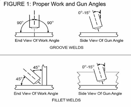
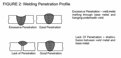
Weld flaws come in all shapes, sizes and degrees of severity. Yet one thing holds true regardless of the application or material on which they occur: They are a common, and costly, cause of downtime and lost productivity. They are also an occurrence that even the most skilled welder can experience. In the GMAW process, specifically, there are several typical weld flaws that can transpire. From porosity to undercut and burn through, each has multiple causes. Fortunately, there are also numerous cures that can help welding operators minimize their frustration over weld flaws and get back to work faster. When gas becomes trapped along the surface or inside of the weld metal, porosity occurs. Like other weld flaws, porosity results in a weak weld that must be ground out and reworked. Causes: Typically, inadequate or contaminated shielding gas is the culprit of porosity. Using a nozzle that is too small for the application, or a nozzle full of weld spatter, can also cause this weld flaw. Having a dirty base metal and/or extending the welding wire too far beyond the nozzle is an additional cause. On warm days, air currents from cooling fans can disrupt the shielding gas envelope around the weld puddle creating this problem. Another common cause is a poor seal or a loose fitting in the shielding gas channel through the welding gun. Any gas leaks have the potential to aspirate air into the gas flow. Cures: To correct porosity, ensure that that there is adequate gas flow (increasing it as needed), and replace any damaged gas hoses or GMAW gun components that may be causing leaks. Also, place a welding screen around the work area if welding outside or in an area inside that is particularly drafty. Check that the nozzle being used is large enough for the application and replace with a larger one if it is not. Remove any spatter build up in the nozzle. Extend the welding wire no more than 1/2 inch beyond the nozzle and make certain that the base metal is clean prior to welding. Slowing travel speed to gain greater shielding gas coverage can also combat porosity, as can keeping the nozzle within 1/4- to 1/2-inch of the base metal during welding. Just as its name implies, burn through results when the weld metal penetrates fully through the base metal, essentially “burning through” it. It is most common on thin materials, particular those that are 1/4 inch or less. Another weld flaw, excessive penetration (too much penetration into the weld joint), can very often lead to burn through. Causes: Excessive heat is the primary cause of burn through. Having too large of a root opening on the weld joint can also result in burn through. Cures: If burn through occurs, lowering the voltage or wire feed speed can help rectify the problem. Increasing travel speed helps, too, especially when welding on aluminum, which is prone to heat build-up. If a wide root opening is the suspected cause of burn-through, increasing the wire extension and/or using a weaving technique during welding can help minimize heat input and the potential for burn through. Incomplete joint penetration or lack of penetration results when there is shallow fusion between the weld metal and the base metal, rather than full penetration of the joint. It can often lead to weld cracking and joint failure. Causes: Insufficient heat input and improper joint preparation are the main causes of incomplete joint penetration. The shielding gas mixture and wire diameter can also be a factor. Cures: There are several cures for incomplete joint penetration, including using higher wire feed speed and/or voltages. Reducing travel speed also allows more weld metal to penetrate the joint, as does preparing and designing the joint properly. The joint should allow the welding operator to maintain the proper welding wire extension (no more than 1/2 inch beyond the nozzle) and still access the bottom of the weld joint. Make sure that the shielding gas or gas mixture, wire type and diameters are recommended for the application. Undercutting is a groove or crater that occurs near the toe of the weld. When this weld flaw occurs, the weld metal fails to fill in that grooved area, resulting in a weak weld that is prone to cracking along the toes. Causes: Excessive heat, as well as poor welding techniques, can both lead to undercutting on a weld joint. Cures: Reducing the welding current and voltage is the first step to rectifying undercutting. Using a weaving technique in which the welding operator pauses slightly at each side of the weld bead can also help prevent this weld flaw. Additional cures include reducing travel speed to a rate that allows the weld metal to fill out the joint completely and adjusting the angle of the GMAW gun to point more directly toward the weld joint. Hot cracking typically appears along the length of a weld or directly next to it almost immediately after the weld puddle solidifies. This weld flaw occurs at temperatures greater than 1,000 degrees Fahrenheit (538 Celsius). There are multiple variations of hot cracking including centerline, bead shape and crater cracks. Causes: Hot cracking can result from several factors. These include poor fit-up or joint design, creating too thin of welds and welding at too high of voltages. High levels of base metal impurities can also cause this weld flaw. In some cases, high levels of specific alloys (boron, for example) in filler metals can cause the problem. Cures: Having the proper joint design and good part fit up is one way to help prevent hot cracking, as it keeps the weld puddle the appropriate size and minimizes the chance of the throat of the weld being too thin. In the case of crater cracking, in particular, using a backfill technique (backing up to fill in the joint fully) can minimize cracking by adding throat thickness to the crater weldment. Careful filler metal selection and shielding gas selection is also imperative. Causes: Most often the cause of incomplete fusion is an incorrect gun angle, although contaminants on the base metal can also cause this weld flaw. In some instances, insufficient heat can be the culprit. Cures: First, clean the base metal properly prior to welding, making sure it is free of dirt, oil, grease or other debris. Next, welding operators should place their GMAW gun at an angle of zero to 15 degrees in order to access the groove of the weld joint fully and keep the arc on the leading edge of the weldpuddle. Increase travel speed as necessary to keep the arc from getting too far ahead of the weld puddle. For joints requiring a weaving technique, holding the arc on the sidewall for a moment can help prevent incomplete fusion. Make certain, too, that there is enough heat input to fuse the weld metal and base metal fully. Increase the voltage range and adjust the wire feed speed as necessary to complete the weldment. Remember, even the most skilled welding operators can experience weld flaws. The key to keeping them from affecting productivity and increasing costs in the welding operation is to identify and rectify the problems as quickly as possible. Proper maintenance of the welding equipment is also imperative. Repair or replace any worn or defective items.
With so many factors to monitor — equipment, weld procedures, filler metals and consumables — it’s inevitable that mistakes will occur in most welding operations on any given day. Human error dictates that a welding operator can easily set a power source and wire feeder to the wrong parameters or trim and install a MIG gun liner improperly. But there are other mistakes that can occur in welding operations on a regular basis — ones that many companies may not even realize that they are making. The reality is, however, that these mistakes can have a significant impact on quality, productivity and a company’s bottom line. Fortunately, they don’t have to happen. Consider these top 10 mistakes involved in running a welding operation, along with some recommendations for solving them. Storing filler metals in an area where they are prone to accumulating moisture or exposed to other contaminants (e.g., dirt, oil or grease) can have an adverse effect on their welding performance. To prevent damage, companies should store filler metals in a dry, clean area with a relatively constant temperature until they are ready for use. Spools and coils of wire that are kept on the wire feeder for an extended period should be covered securely with a plastic bag or removed from the wire feeder and stored in the original packaging. An enclosed wire feeder can also protect against contaminants. Such precautions prevent damage that can lead to poor weld quality, and ultimately, rework. It is important for companies to use the best equipment for the job. Repurposing old or dilapidated power sources, welder/generators or wire feeders can cause quality issues, not to mention downtime and additional costs for troubleshooting problems that inevitably arise from using dated equipment and technology. Instead, companies should consider the newer technologies available in the marketplace, recognizing the advantages these can offer in terms of improving weld quality and productivity. In most cases, newer equipment can provide companies with a quick return on investment and greater long-term savings – in a relatively short payback period. Newer technologies often offer benefits like improved power efficiency, better deposition rates, lower weld prep time and faster training, all of which ultimately add up to greater arc-on time and productivity. Performing a thorough cost-savings analysis before buying new equipment can help companies assess their potential return on investment, as well as justify the capital expenditure. Using a too-low or too-high amperage MIG gun can lead to unnecessary costs for purchasing and replacing this equipment. Welding operators rarely spend the entire day welding or welding continuously, as there is downtime for part preparation, movement and/or fixturing. For that reason, it may be possible to use a lower amperage MIG gun or one with a lesser duty cycle on some applications. For example, using a lighter and smaller 300-amp MIG gun instead of a 400-amp model can provide welding operators with greater maneuverability and reduce downtime for fatigue. Lower amperage MIG guns tend to cost less, as well. Conversely, on higher amperage applications and/or those that require longer periods of welding, it is important to use a higher amperage gun. Skimping and purchasing a lower amperage MIG gun in this situation can lead to overheating, premature failure and greater long-term costs. Companies should consult with a trusted welding distributor for MIG gun recommendations for their application. It is not uncommon for companies to preheat too little or skip this portion of the Preventive maintenance (PM) is a frequently overlooked part of the welding operation, but it is critical to preventing unscheduled downtime and keeping repair costs low. A well-performed PM program can also help increase productivity, extend equipment life and create a workplace philosophy that encourages shared responsibility for, and interest in, preserving the integrity of the welding equipment. Companies should develop a regular timetable to inspect their power sources, wire feeders and MIG gun or TIG torches during scheduled downtime in production. Between welding shifts is often enough time to perform routine inspections. Checking consumables regularly for spatter build-up — and replacing these components as needed — is also an important part of a viable PM program. Using the correct type and/or mixture of shielding gas can help companies prevent weld defects, minimize excessive spatter and reduce costs for rework or post-weld cleanup. Shielding gases also determine arc characteristics and weld penetration on a given application. Straight CO2 provides good weld penetration, but it is prone to spatter and has a less stable arc than mixtures that include argon. High argon mixtures (a minimum of 85 percent argon for solid wire or as low as 75 percent for metal-cored wires) are the best choice. These mixtures can be used in the spray transfer process to promote higher deposition rates and generate less spatter. For TIG welding, the appropriate argon/helium mixture can improve speed, quality and arc characteristics. For both MIG and TIG welding operations, companies should purchase their shielding gas from a reputable welding distributor and be certain that it meets the purity requirements for their application. All gas delivery systems should be free of contaminants that could enter the weld puddle and welding operators should use the correct shielding gas flow rate. Too little gas flow won’t properly shield the molten weld pool, while too much flow can cause turbulence and aspirate air into the weld puddle. Protecting the weld puddle from drafts is also critical. Due to the initial up-front cost savings, the temptation may be great for companies to purchase less expensive filler metals. However, doing so can often lead to greater long-term costs and lower productivity levels. It is not uncommon, for example, to experience downtime associated with poor wire feeding, excessive spatter or, potentially, weld defects when using lower quality filler metals. Companies may also find themselves experiencing an excessive amount of time for non-value-added activities (those that do not directly contribute to their throughput), such as applying anti-spatter and post-weld grinding or rework. For that reason, it is important to look at the total cost of using particular filler metals, as opposed to the per-unit cost. If more expensive, higher quality filler metals can minimize labor costs for non-value-added activities and provide better weld quality and/or greater productivity, then the higher up-front cost makes good sense in the long run. Skipping steps in weld preparation can lead to weld defects, rework or scrapped parts. Welding operators should always take care to clean the base material before welding to prevent contaminants like dirt, oil or grease from entering the weld puddle. Similarly, monitoring part fit-up is a critical part of the pre-weld process. Welding operators should carefully assess the weld joints to ensure there are no excessive gaps, as poor part fit-up can lead to issues like burn-through or distortion on all materials, but particularly when welding on materials like aluminum or stainless steel. Clamping or fixturing a part in the correct position is also a good practice to help protect materials like stainless steel against distortion or buckling. It is not uncommon for companies to overlook the importance of their MIG gun consumables. Unfortunately, that oversight can lead to a host of problems, including unscheduled downtime for changeover and/or rework of weld defects caused by a poorly performing contact tip, nozzle or liner. To help avoid problems, select consumables with a tapered design that locks conductive parts together to reduce heat buildup. Contact tips with coarse threads are a good way to speed up replacement and make sure installation is accurate. Look for consumables where the diffuser locks and aligns the liner with the contact tip and power pin for flawless wire feeding. These systems also offer error-proof liner installation with no measuring required; the liner is simply locked in and trimmed flush with the power pin at the back of the gun. As with other parts of the welding operation, investing time and money in training can yield significant long-term benefits for companies. Not only do welding operators benefit individually from process and equipment training, but in many cases it can also help them optimize the welding operation for greater efficiency. Too, proper training can give companies a competitive edge over those who have less-skilled labor and it promotes greater teamwork among employees. Typically, training opportunities are available through equipment and filler metal manufacturers or through welding distributors. In some cases, working with a local technical college can lead to training for specific applications and markets, allowing companies to bring in welding operators who are already trained for a given application and better promote their position in a given industry. Making mistakes is human nature, but with some careful consideration, it is easy to avoid some of the more common ones associated with running a welding operation. Measuring out long-term savings, versus cutting costs up front, is a particularly good way to avoid pitfalls that could lead to excessive downtime, quality issues or lost productivity. And it can have an excellent impact on a company’s bottom line.
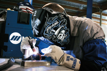
It’s tough to stay cool in the hot summer months, let alone when you are “under the hood” welding. Unfortunately, that heat can take a toll on your body, mind and performance. In addition to affecting your mental acuity – causing loss of concentration or, in extreme cases, confusion – excessive heat can also affect your motor skills, cause irritability and increase fatigue. Consuming liquids throughout the day is a critical part of staying cool. It is also helpful to supplement that approach with smart equipment selection and other cooling options. Consider these tips. As a general rule, selecting the lightest, most flexible MIG gun for the application is the best choice. In the case of a 400-amp application, a MIG gun rated at 300 amps may suffice for your application. That is because MIG gun amperages reflect the temperatures above which the handle or the cable on a MIG gun becomes uncomfortable. They do not indicate the point at which the MIG gun risks damage or failure. Also, you spend time in the day doing other things besides welding – moving parts, prepping materials or fixturing them. It’s highly unlikely that you will be operating the MIG gun at full amperage and full duty cycle at all times. Duty cycle is defined by the amount of arc-on time in a 10-minute period that the equipment can be operated at maximum capacity. Some MIG guns will offer 100 percent duty cycle, while others are rated 60 percent or below. It is important to research the MIG gun’s duty cycle prior to purchasing it in order to ensure it offers the necessary capacity for the application. But in most cases you don’t have to match your MIG gun amperage to the exact amperage of your application to get the job done. A lower amperage MIG gun can often suffice and keep you cooler. Selecting a MIG gun with the appropriate handle, neck and cables for your application can also help you stay cool. Typically, as a MIG gun’s amperage decreases so too does the size of the gun handle and the cable. That decrease in size and weight can help minimize the amount of energy you exert and reduce heat stress. Decide what type of MIG gun handle is most comfortable for you. MIG gun manufacturers often offer handles in curved and straight models. Regardless of the one you choose, make sure it is a lightweight, comfortable style that also meets the MIG gun and application’s amperage and duty cycle requirements. Typically, a smaller handle will be easier for you to maneuver. Additionally, some MIG gun manufacturers offer ventilated handles, which help reduce heat and are more comfortable to hold when welding for longer periods of time. In some instances, a water-cooled MIG gun may provide the smaller size desired for an application and would be a good choice to reduce fatigue on higher amperage applications, especially in a shop setting. When selecting power cables, choose the smallest and shortest power cable possible that can still meet the needs of your application. Smaller and shorter power cables are lighter and more flexible, and can help reduce your fatigue. They can also minimize clutter in the workspace and prevent excessive coiling that may be cumbersome to unravel or that could lead to poor wire feeding. An added advantage is that smaller and shorter cables tend to be less expensive, as well. Also, consider using a MIG gun with a rotatable or flexible neck to minimize unnecessary movement. Flexible necks can be easily adjusted to fit different welding angles. This feature helps minimize additional straining to reach a particular weld joint, and reduces the risk of fatigue or injury. Similarly, rotatable necks are a good option for welding out-of-position (including overhead), as they can be adjusted to reach the weld joint without changing the gun handle or its position. Bernard offers neck couplers, too, which allow you to connect multiple necks together to reach especially difficult joints more comfortably. Cooling vests are one option for beating the summer heat, but these can make some people uncomfortable and actually increase fatigue. Instead, you may want to consider a lighter cooling option like a cooling belt. For example, the CoolBelt™ from Miller Electric Mfg. LLC (an Illinois Tool Works company that Bernard is a division of) provides constant airflow over the welder’s head and face. The fan on the CoolBelt is secured on the lower back. Air flows upward through a piece of tubing that fits into your helmet; it’s then dispersed through the vents. The CoolBelt can reduce the temperature as much as 17 degrees. One advantage of the CoolBelt, compared to a cooling vest is its weight — it is significantly lighter so it helps improve stamina throughout the workday. Additionally, the CoolBelt doesn’t obstruct your range of motion, allowing you to perform more efficiently. Find Additional Safety Gear to Meet Your Personal Protection Needs
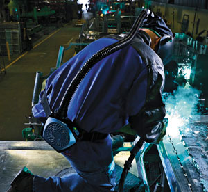
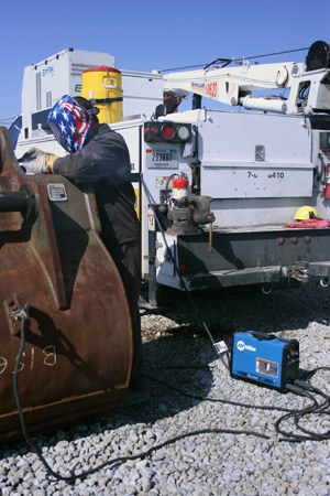
For companies faced with training new welders, it is important to instill good habits early in the process. Doing so helps ensure the welders are well prepared not only to create quality welds, but also to contribute positively to the operation’s productivity. It can also help the welders gain the confidence they need to become increasingly proficient. Following are 10 important things to teach new welders, to help them improve their skills and stay safe in the process. 1. Make safety a priority: It is critical that welders protect themselves from the heat and electricity generated by the welding process with the proper personal protective equipment (PPE). The arc is dangerous to both the eyes and skin. PPE includes: flame-resistant gloves, safety glasses, a welding helmet and a long-sleeved welding jacket. Flame-resistant clothing and steel-toed shoes are also recommended. Both the American Welding Society (AWS) and OSHA offer guidelines for PPE for specific environments. Be sure to use enough ventilation, local exhaust at the arc, or both to keep the fumes and gases below the Permissible Exposure Limit (PEL)/Threshold Limit Value (TLV)/Occupational Exposure Limits (OELs) in the breathing zone and the general area. Always train new welders to keep their heads out of the fumes. Explain the importance of reading and understanding the manufacturer’s instructions for equipment, your company’s safety practices, and the safety instructions on the label and the material safety data sheet for the filler metals being used. Routinely check for proper ground connections and stand on a dry rubber mat (indoors) or a dry board (outdoors) during welding to minimize the possibility of electrical shock 2. Install consumables properly: Good conductivity (the ability for the electrical current to flow along the welding circuit) helps gain good weld quality. New welders should always install their consumables – diffusers, nozzles, contact tips – according to the manufacturer’s recommendation, making sure that each component is securely tightened. In a gas metal arc welding (GMAW) operation, for example, the connection between the GMAW gun neck and diffuser needs to be secure to prevent shielding gas leaks. Secure connections also provide the surface area necessary to carry the electrical current throughout the GMAW gun to create a stable arc. Good connections also help prevent weld defects, support consistent productivity and reduce the risk of premature consumable failure due to overheating. 3. Cleanliness is critical: Dirt, oil, grease and other debris can easily enter the weld pool causing contamination that leads to poor weld quality and costly rework. Excessive oxidation and moisture can compromise quality weld. New welders need to learn proper cleaning procedure for the base material they are welding. In some cases, wiping the base material with a clean, dry cloth may suffice. However, welding on aluminum, for example, requires the use of a stainless steel wire brush designated for aluminum to clean out the joint before welding. A wire brush removes dirt and any of the oxides that may still reside on material surface. Regardless of the material, it is important to follow the proper instructions for cleaning before welding. 4. Always follow welding procedures: Welding procedures are the “recipe” needed to create consistent welds and should be followed at all times. The procedures for a given application have been carefully determined and qualified by experts to ensure that the recommended parameters are capable of yielding the desired results. Weld procedures include the required shielding gas mixture, recommended gas flow rate, and voltage and amperage ranges. These procedures also provide information on the type and diameter of filler metal to use, as well as the proper wire feed speed in the case of a GMAW or flux-cored arc welding (FCAW) application. 5. Understand the importance of filler metals:New welders can benefit from familiarizing themselves with the attributes of various types of wires, including flux-cored and metal-cored wires, as well as the techniques for welding with each type. For example, they should learn whether their filler metal requires a “push” or “pull” technique. Following old adages like, “If there’s slag, then you drag,” can help; it indicates that flux-cored wires, which produce slag, should be operated using a pull technique. New welders should also become familiar with the manufacturer’s specification sheet for additional operating recommendations. Learning to handle and store filler metals properly is also critical for new welders to learn. They should always wear clean gloves when handling filler metals and if they are responsible for storing them, should do so in a clean, dry environment. 6. Stay comfortable: Keeping cool and comfortable during the welding process can help welders lessen the chance of injuries associated with repetitive movement and reduce overall fatigue. When possible, new welders should learn to minimize cumulative strength moves, material handling or constant motion. They should also use a GMAW gun with a comfortable handle and cable style, as these factors contribute to the equipment’s maneuverability. New welders should be encouraged to play an active role in improving workspace ergonomics. Typically, the more input a welder offers about the job, the more satisfied he or she will be. Plus, that involvement can help ensure greater safety compliance and lower workers’ compensation costs for injuries. 7. Know the material properties: Every material has different mechanical and chemical properties. Helping new welders understand the difference between materials — particularly how they react to heating and cooling — is a key component of training. For example, austenitic stainless steel conducts heat at around half the rate of mild steel, but has a much higher rate of thermal expansion when welded; it also has a more localized heat affected zone (HAZ) that can lead to buckling when the weld cools. Welders who are aware of such properties can take precautions such as clamping to prevent distortion. Similarly, many materials require pre- and post-weld heat treatments to control the cooling rate and prevent cracking. When welders are familiar with such material attributes, they’re better prepared to make necessary adjustments during the welding process. 8. Visually inspect the welds:Knowing how to conduct an accurate visual inspection of a completed weld is the first step in quality control. It is also the quickest and least expensive method of inspection. New welders should learn how to identify weld defects that have porosity, for example, since the presence of this weld defect on the surface often indicates a similar problem throughout the weld. Identifying the defect early on helps prevent the time and cost associated with other testing methods, including x-ray or NDT (non-destructive testing) inspections. Other defects that new welders should learn to identify include lack of penetration (high, ropey welds), excessive penetration (sunken welds) and undercutting (characterized by a notch in the base material). It is important that welders inspect for weld cracks, which are among the most common weld defects to occur. 9. Learn how to troubleshoot: Identifying and rectifying welding problems quickly is a key skill for new welders to learn. Good troubleshooting skills not only help reduce downtime, but they also contribute to good weld quality and productivity. Such skills can also help reduce costs associated with rework. New welders can benefit from learning how to adjust gas flow rates properly and/or identify gas leaks in order to solve instances of porosity. They should also know how to make adjustments to amperage and voltage settings if they encounter issues such as lack of penetration, excessive penetration or undercutting. Identifying welding problems associated with worn consumables is also important, since poor conductivity can result in an unstable arc and lead to a variety of weld defects. 10. Maintenance makes a difference: From the power source to the GMAW gun and consumables, every part of the welding system requires maintenance to keep it operating efficiently and effectively. New welders should become familiar with proper maintenance procedures — preferably preventive ones — as part of the ongoing upkeep of the entire welding system. Regularly checking that the connections throughout the length of their gun or torch are tight is important, as is visually inspecting the front-end consumables for signs of wear. In the case of a GMAW gun, the welder should replace nozzles or contact tips that have spatter buildup on them to prevent issues such as poor gas coverage or an erratic arc that will likely lead to weld defects. Welders should regularly check the power source, primary power line, gas cylinders and gas distribution system to ensure that they are working properly. They also need to replace faulty gas regulators or cables and hoses that show signs of wear, cracks or damage.The Basics: MIG Troubleshooting
The Basics: MIG Troubleshooting
Keep Covered
Don’t Be Undercut
Keep Track of the Heat
All About Wire
No Cure-All
Related Articles
Thoughts for Improving Welding Operations in Today’s Automotive Industry
From Technology to Technical Support:
Thoughts for Improving Welding Operations in Today’s Automotive Industry
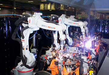
into the welding process can help ensure the necessary uptime
for automotive applications.Equipment Standardization
Single Arc Pulsed Technology
Streamline Vendors
Error Proofing
Best Practice Meetings
Preventive Maintenance
Coopetition
Built-in Buffers
Addressing Welding Challenges in Today’s Automotive Industry
Addressing Welding Challenges in Today’s Automotive Industry
Well-Managed Inventory Equals Greater Uptime
of best practices can help automotive companies “do more with less.”The Right Equipment Maintained Properly
Meeting the Demands
MIG Welding Shielding Gas Basics
MIG Welding Shielding Gas Basics
Choosing The Right Shielding Gas
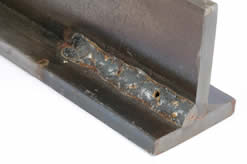
of the weld bead, can be caused by inadequate shielding gas and can dramatically weaken
the weld. Carbon Dioxide (CO2)
Argon
Oxygen
Helium
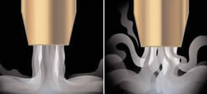
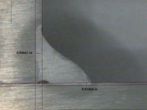
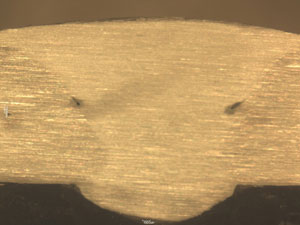
in shielding gas coverage. The photo on the left shows good coverage, while the coverage in the photo on the right allows
the air environment contaminate the shielding gas.Getting the Shielding Gas to the Weld Pool
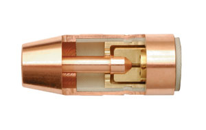
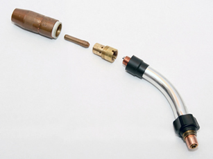
contact tip is seated in the diffuser and held in place
by the spatter guard inside the nozzle.The Causes of GMAW Flaws
The Causes of GMAW Flaws … and the Cures to Help Welding Operators Get Back to Work Faster
Porosity
or the GMAW gun are free of leaks can help solve the problem.Burn Through
Incomplete Joint Penetration (Lack of Penetration)
Undercutting
Hot Cracking
Incomplete Fusion
When the weld metal fails to completely fuse with the base metal or with the preceding weld bead in multi-pass applications, incomplete fusion can occur. Some people also refer to this weld flaw as cold lap or lack of fusion.10 Mistakes in Running a Welding Operation and How to Fix Them
10 Mistakes in Running a Welding Operation and How to Fix Them
Mistake No. 1: Improper Filler Metal Storage and Handling
Mistake No. 2: Repurposing Old Equipment
Mistake No. 3: Using the Wrong Size MIG Gun
Mistake No. 4: Improper Preheat or Interpass Temperature Control
weld procedure altogether. Yet preheating is one of the biggest deterrents against cracking, as it slows down the cooling rate after welding. The type and thickness of the material being welded will determine preheat and interpass temperature. These requirements can be found in the application’s welding procedure, welding codes or other fabrication documents. For the best results, welding operators need to preheat the material completely through and extend the heated area to approximately three inches on either side of the weld joint. Welding should commence while the material is at or above the preheat temperature. Allowing the weldment to cool below the required interpass temperature may also lead to cracking.Mistake No. 5: Ignoring Preventive Maintenance
Mistake No. 6: Shielding Gas Inconsistencies
Mistake No. 7: Purchasing Filler Metals Based on Cost Only
Mistake No. 8: Improper Weld Preparation
Mistake No. 9: Disregarding MIG Gun Consumables
Mistake No. 10: Overlooking Training Opportunities
Stay Cool When Welding In The Summer Heat
Stay Cool When Welding In The Summer Heat
Tip One: Don’t go over amperage
Tip Two: Get a good handle
Tip Three: Stay light and flexible
Tip Four: Consider a cool option
Teaching New Welders to Improve Quality and Productivity
Teaching New Welders to Improve Quality and Productivity
![]()
![]()