Tico Adopts Bernard MIG Welding Guns & Consumables
Using Bernard® Q-Gun™ semi-automatic air-cooled MIG guns and Centerfire™ consumables, Tico Terminal Trucks and Trailers improved productivity and reduced welding costs.
Learn what Graham Corporation has to say about Bernard® MIG guns and consumables.
Bernard® MIG welding consumables help Taylor Machine Works save time by reducing contact tip changeover in its forklift welding operations. Since converting to Centerfire™ consumables, the company has gone from requiring multiple contact tip changes per day to only one on average per welder. The contact tips can be changed without tools, which saves time, plus they are heavier duty than Taylor’s previous brand, so they last longer. During the original trial of the consumables, Taylor even had one welder go 27 days without changing a contact tip! The gas diffusers and nozzles are also long lasting, so Taylor’s welders can spend more time welding and have less downtime for changeover.
Taylor Machine Works saves money by welding its forklifts with Bernard® MIG guns — all parts are replaceable, and the necks adjust to fit tight joints. The company’s previous MIG welding guns required downtime to take apart for maintenance and repair and were typically disposed of instead. The Bernard MIG guns make it quick to connect new parts, including swapping out necks. The necks are also rotatable so welders can adjust them to new angles to make it more comfortable to weld in hard-to-reach areas.
Tulsa Welding School’s Houston campus needs reliable equipment that can handle any process. Bernard® MIG guns and consumables are the answer. You can count on Bernard BTB semi-automatic air-cooled MIG guns to deliver industrial-grade performance and reliability in the most demanding environments as well as optimize welder ergonomics and weld access. Bernard contact tips, nozzles and diffusers are easy to use and high performing – they provide better arc starts, less spatter and more consistent welds – and also last up to three times longer than competitive brands.
Blinn College welding school instructors and students agree – Bernard® MIG guns and consumables are the welder’s best choice in dependability and easy to use. You can count on Bernard BTB semi-automatic air-cooled MIG guns to deliver industrial-grade performance and reliability in the most demanding environments as well as optimize welder ergonomics and weld access. Bernard contact tips, nozzles and diffusers are easy to use and high performing – they provide better arc starts, less spatter and more consistent welds – and also last up to three times longer than competitive brands.
Watch as we compare the time it take to change Bernard® Centerfire™ consumables on our BTB MIG Gun compared to our competitor.
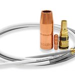
As you support more inexperienced welders, choosing equipment with fewer points of failure and simplified maintenance can reduce training and shorten your troubleshooting list. Learn more about Bernard® AccuLock™ S consumables.
Meet Sam, a semi-automatic MIG Welding Supervisor at an Industrial Company. Sam’s faced with increasing manufacturing growth putting production throughput and quality targets at an all time high. Everyday Sam wastes valuable time troubleshooting welding issues related to poor wire-feeding such as birdnesting, burnbacks and erratic arc, which all leads to poor weld quality. What if there was a solution for Sam? Introducing AccuLock (Semi-Auto) Consumables: Shorten Your Troubleshooting List: With AccuLock Consumables, SAM (and you) can… Load and Lock for Better Productivity, reduced troubleshooting, downtime and rework. Load and Lock with Bernard® AccuLock™ S consumables.
Challenged by increasing welder retirements and turnover while orders keep growing year over year? As you support more inexperienced welders, choosing equipment with fewer points of failure and simplified maintenance can reduce training and shorten your troubleshooting list. Bernard® AccuLock™ S consumables provide error-proof liner replacement every time — no measuring required!
Bernard® AccuLock™ S liners are locked and concentrically aligned to both the contact tip and the power pin without the use of fasteners to guarantee optimized wire feeding, which eliminates welding liner misalignment and gaps from your troubleshooting list.
Have you ever timed the difference between changing a rear-loading liner and a QUICK LOAD® Liner? We have! As the clock counts away, it took 2:05 minutes to change a QUICK LOAD Liner. As the robot using the QUICK LOAD Liner is already up and welding, the rear-loading liner continues to be installed. There are many benefits to using a QUICK LOAD Liner in addition to reducing downtime. A gun that stays connected to the feeder during liner replacement increases safety, reduces scrap and reduces wear. It also increases safety as there is no need to climb up to boom-mounted feeders or enter robotic cells. It reduces scrap wire as liners are removed and replaced over the wire. Reducing wear on the gun power pin, worn o-rings can cause gas leakage and poor weld quality. It took 3:31 minutes to change the rear loading liner — that’s 40% more production downtime! This was an ideal setup with an easily accessible feeder rear-loading liner replacement downtime increases as access to the feeder becomes more challenging. QUICK LOAD Liner Less Downtime, Less Waste, More Safety. Watch as we compare the time it takes to replace a liner. QUICK LOAD® liners are able to be replaced in half the time of a conventional rear-loading liner.
Changing a conventional liner can cost you in more ways than one. The Tregaskiss® QUICK LOAD® liner AutoLength™ system can help you eliminate those costs.
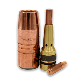
Tregaskiss® AccuLock™ R consumables are designed for increased tip life, which can reduce your replacement frequency and related planned downtime. The longer lifespan of AccuLock contact tips means fewer human interactions within your welding cells and fewer accidental errors as a result. With contact tip cross-threading issues also virtually eliminated, you’ll spend less time troubleshooting and more time on proactive weld quality and productivity initiatives.
Tregaskiss® AccuLock™ R consumables are designed for increased tip life, which can reduce your replacement frequency and related planned downtime. AccuLock HDP contact tips can increase life by an additional 10x or more in pulse welding applications.
Tregaskiss® AccuLock™ R consumables are designed for increased tip life, which can reduce your replacement frequency and related planned downtime. AccuLock HDP contact tips can increase life by an additional 10x or more in pulse welding applications. In most cases, your current tip and diffuser can be replaced with no impact to tool center point (TCP), making this upgrade low effort, low risk, and high payoff.
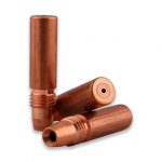
Contact tips are often referred to as the smallest fuse in the fuse box that is your robotic welding cell. But this small fuse can have a big impact on productivity. In terms of overall efficiency, the contact tip is key. Contact tips depend upon repeatability to be effective in the welding process. Learn more about the different types of available — and how choosing the right one for your application can improve results and save money. How do contact tips affect efficiency? When an operation changes contact tips every few hours, there is an obvious effect on productivity. It requires the weld cell to be shut down, and the operator may have to enter the cell to change out the tip. If the robot is buried inside the welding line, contact tip changeover takes even longer. Not only are these changeovers inefficient, but they also introduce the potential for mistakes. Every time a human interacts with the robot, there’s a risk of incorrect consumable installation or other improper adjustments that can lead to poor quality welds and costly rework. Choosing the right tip depends on the results you’re looking for and the needs of the application. In the automotive industry, for example, choosing a quality contact tip is critical since unplanned downtime is the enemy of a high-volume multi-robot operation. Contact tips in these applications need more wear resistance. A high-quality contact tip provides a longer life and a more consistent and stable arc. Longer tip life results in more robot uptime, less time wasted on non-value-added labor for tip changeovers and reduced human interaction with the robot that could lead to error. But the contact tip itself isn’t the only factor impacting tip life — the welding wire, part fit-up, robot programming and grounding also contribute. Different types of contact tipsThere are several types of contact tips available. Understanding the differences can help you select the best choice for your operation. 1. Copper contact tips: Contact tips made from this material are the most conductive to transfer welding current. But copper is also the softest option and will keyhole (or wear the bore unevenly) much faster. If keyholing is a pain point in your operation, this may not be the best choice. The initial cost of copper contact tips tends to be cheaper than other options. 2. Chrome-zirconium contact tips: This alloy provides better wear resistance and longer life than copper tips, holding up better to the demands and increased arc-on time of robotic welding. They are slightly less conductive than copper tips, but they are still sufficient for most robotic applications. 3. HDP contact tips: HDP tips can last 10 times longer than copper tips — and up to 30 times in some cases — depending on the application and waveform being used. Operations may be able to go from changing contact tips every two hours to only changing tips once a week. HDP contact tips are engineered to endure wear better, providing increased resistance to arc erosion in pulsed welding, as well as spray transfer and CV MIG. The precise fit between the tip and the wire also results in good arc stability to help produce high-quality welds. Because HDP contact tips reduce the impact of the welding current decline over time, they can provide a more stable and consistent arc over the life of each contact tip. These tips work best in applications that use high-quality copper-coated solid wire. Common pitfalls with contact tips 1. Only considering price: Many operations may look only at the price per tip when they purchase contact tips. But it’s important to look beyond the initial price and consider the big picture, which includes the downtime and labor required for changeover, along with any quality issues that may be happening in the weld cell. If a contact tip lasts three times as long, the robot can continue to weld instead of being down for a tip changeover — and there is less human interaction inside the cell . 2. Ignoring ID tolerance issues: The size and cast of the welding wire are important in making a decision about contact tips. Some tips need to be undersized for the welding wire used, while some tips need to match the wire size. And the same exact wire will vary in the necessary contact tip size depending on if the wire comes in a small spool or a 1,000-pound barrel. For most copper and chrome-zirconium tips, it’s recommended to undersize the contact tip by a single wire size when using a 500-pound barrel or greater of wire due to the wire cast. With smaller sizes of wire packaging, use contact tips that match the wire size. The goal is to maintain a clean, consistent contact between the wire and the tip so the weld current is conducted as efficiently as possible. 3. Using poor quality wire: In most cases, poor quality welding wire will lead to poor results from your contact tips. This is due to the lubrication on the wire, as well as the consistency of the wire diameter; inconsistent wire diameter wears the tip faster. Choosing a higher quality wire can improve tip life and produce better results. Also, be aware that wires without a copper coating and cored wires wear tips much faster. Using copper-coated solid wires typically slows contact tip wear. 4. Not being open to change: Some companies think the status quo is fine because they aren’t experiencing issues. They change tips in the robotic welding cell every couple of hours, even if those tips don’t need to be changed. Looking at the true length of their current tips or investing in higher-quality tips could optimize efficiency and the overall process — saving unplanned downtime and reducing the need for non-value-added labor hours. Analyzing the robotic operation So how can companies best analyze their robotic welding operation to determine when to change to a different type of contact tip? Contact tips react differently to different applications, so an important first step is to run trials with varying quality levels of tips. This will provide an accurate comparison and a level set for expectations. Run each tip to failure, including the current brand, rather than proactively changing the tip on a set schedule. Be sure to log the time each part lasted. Ideally, run multiple contact tips in any trial to eliminate any outliers. This type of trial can help to identify how much labor time is spent on tip changeovers, how much robot uptime can be achieved and what failures are occurring with each type of contact tip. If an operation previously experienced 10 burnbacks a day and reduces that to zero by using a higher quality contact tip, this can help eliminate unplanned downtime. Optimizing contact tip efficiency in robotic welding In many cases, equipment-based solutions can be a means to gain success in the robotic welding operation. They can mitigate costly risks and eliminate issues that lead to inefficiencies. And often, these issues are related to a small but significant part of the robotic welding process — the welding consumables. Changing over consumables can be a time-consuming part of maintaining the welding cell, especially if it is done multiple times during a shift. Changeover can also negatively impact productivity and quality if the consumables are installed incorrectly. Unfortunately, given the industry’s current lack of skilled welders, that may be a common occurrence. Welders simply have less experience with proper installation processes. To address this problem, many companies tend to spend more time and money on training and troubleshooting. They may even have to find workarounds to problems in the weld cell as employees get up to speed. All of this occupies resources. Welding consumables — the contact tip, gas diffuser and nozzle — can be a major source of downtime in robotic welding operations, unplanned or planned. During installation, cross-threading of contact tips by less experienced welders is a common occurrence that can result in unplanned downtime. Cross-threading leads to multiple problems beyond the lost productivity for contact tip changeover. First, it can negatively affect tool center point (TCP), causing the robot to weld off-seam and create quality issues like lack of fusion or poor penetration. Personnel overlooking the robotic welding cell then need to stop production to address rework and/or scrap the part. Cross-threading can also create a keyhole, or uneven wear, in the bore of the contact tip. A keyhole the size of only half the diameter of the wire can result in the robot welding off-seam. Many times, a cross-threaded contact tip will stick inside the welding gas diffuser. Without another gas diffuser readily available, the operator has to make a trip to the tool crib for a new one. Meanwhile the robot is offline and not producing parts. Plus, a company incurs costs for both the contact tip and the diffuser’s replacement. Companies that invest in power sources with a pulsed waveform capability — particularly in the automotive industry — often schedule planned downtime. Pulse waveforms improve productivity and quality by increasing travel speeds, providing a more consistent arc and reducing spatter. However, the pulsing action of the arc electrically and mechanically erodes the contact tip, leading to faster wear. It is necessary to plan downtime as a preemptive strike against contact tip failures before the chance of associated weld quality issues arise. Both unplanned and planned downtime cost money and occupy available labor for non-value-added activities — tasks that don’t support throughput and productivity. There is a new welding consumables technology that can help. To address the issue of cross-threaded contact tips, Tregaskiss designed its AccuLock™ R consumables. The design is intended to support higher throughput, provide a long service life and ensure good weld quality. The AccuLock contact tip features a long tail that concentrically aligns within the diffuser before the threads engage. The threads are also coarse, so they require minimal rotations to install. This design virtually eliminates the risk of cross-threading and provides three key benefits to the robotic welding operation: The contact tips also have greater mass at the front compared to other designs, along with a taper that mates securely with the gas diffuser. The tapered surfaces ensure optimal conductivity, reduce heat and keep the consumables locked in place. These features — combined with the fact that 60% of the contact tip is buried in the diffuser, away from the heat of the arc — make the consumables last longer. Extending the product life means there is less need for changeovers. AccuLock R consumables can also address the accelerated wear of contact tips caused by pulsed waveforms. In addition to offering the contact tips in copper and chrome zirconium, Tregaskiss has an AccuLock HDP option. The HDP contact tips last more than 10 times longer than copper tips in pulsed MIG welding applications. As a result, companies can reduce unplanned downtime for contact tip changeover — and make those changeovers faster because of the easy-to-install design. AccuLock R consumables can be implemented easily. Switching from many other consumables typically doesn’t affect TCP or robotic programming; however, it is best to consult directly with Tregaskiss to confirm this is the case. For companies that have both robotic welding and semi-automatic welding operations, the AccuLock R consumables can simplify complex inventories. The contact tips are part of a Common Consumable Platform™ and can be used across a wide range of Tregaskiss® robotic and fixed automatic MIG guns, as well as with Bernard® semi-automatic MIG guns (ranging from 200 to 600 amps). This common contact tip can reduce inventory costs and lessens the opportunity for operators to install the wrong consumable. The AccuLock R gas diffuser also has a blue o-ring to distinguish it from other diffusers. When companies find equipment solutions, like the AccuLock R consumables, that help reduce troubleshooting and downtime in their robotic welding operations, opportunities can increase. The ability to improve productivity and quality is at the forefront of those. But there may also be more time available to optimize the weld cell, make positive changes to workflow or material handling and seek out cost savings.In some cases, companies may also uncover issues in the weld cell that were previously masked by frequent contact tip changeovers. Now, however, there is more time address those to generate greater efficiencies in the operation. In short, with the right consumables, there is more time to focus on reaching improvement targets and increasing throughput — and on implementing training that can help achieve those goals.
MIG welding gun configurators, like the Bernard® BTB semi-automatic air-cooled MIG gun configurator, allow you to choose specific styles or types of consumables to match the demands (amperages and waveforms) of your application. Know the wire size and type when choosing the size and style of contact tip. Joint access, operating temperatures and arc-on time are important considerations in choosing the right welding nozzle. Having the right MIG gun liner helps minimize downtime to address wire feeding issues. It is important that you always trim the liner to the proper length. Consider these tips: Note, selecting the same welding consumables across multiple weld cells, when possible, can help with inventory management and can be more cost-effective. Visit the Bernard® MIG gun configurators
MIG welding consumables are a critical but often overlooked part of the welding operation. Unfortunately, without a clear understanding of the problems that can arise with consumables — and the best way to fix them — companies stand to lose productivity, jeopardize quality and increase costs. In some cases, the biggest issue is choosing the wrong consumable for the job. Consider this real-life example: A company with 90 arcs is using five contact tips per day, per welder — that adds up to 450 contact tips a day. By simply changing to a more robust consumable system, the company could potentially use one contact tip per welder every three to four days. The savings in reduced downtime and purchasing costs in this situation is significant. So how can companies avoid common pitfalls? A willingness to look at the impact of welding consumables on the overall operation — not just the product purchase price — is key. Training is also a vital part of success. Welding operators and maintenance personnel should know how to properly select, install and maintain consumables and troubleshoot problems when they arise. Or better yet, understand how to prevent them in the first place. Welding nozzles play an important role in the welding operation, directing shielding gas to the weld pool to protect it from contaminants. Incorrect contact tip recess within the welding nozzle is among the biggest problems. The more the contact tip is recessed, the longer the wire stickout, which can lead to an erratic arc and increased spatter in the nozzle. It can also negatively impact shielding gas coverage. In approximately 90% of applications, a 1/8-inch contact tip recess provides the best shielding gas coverage with a welding wire stickout that helps support consistent arc stability. Using the wrong welding nozzle for the application can cause downtime for changeover due to premature failure. For a standard welding application (100 to 300 amps), a copper nozzle provides good heat resistance. Copper nozzles also resist spatter buildup. For higher-amperage applications (above 300 amps), a brass welding nozzle is the better choice. Brass does not anneal as fast as copper, so the welding nozzle will maintain its hardness longer under higher temperatures. Choosing the wrong shape and size of nozzle can be problematic. Too large of a nozzle can make it difficult to obtain the joint access needed to complete a sound weld. Long or short tapered nozzles work well for restricted joints. However, there is an increased risk of spatter buildup due to the narrower bore, which can shorten the consumable’s life. To gain good gas coverage, use a longer nozzle when possible. MIG welding contact tips provide the current transfer to the welding wire to create an arc. Using a contact tip with an inside diameter (ID) that’s too small can lead to poor wire feeding and, potentially, a burnback. Using a tip with too large of an ID can cause the welding wire and arc to wander. Every consumables manufacturer has proprietary formulas for gauging contact tip ID and implementing it into their design. Select a high-quality contact tip for consistent tolerances, and match the contact tip ID to the diameter of the welding wire to gain the best electrical conductivity. This happens because the contact tip ID is actually slightly larger than the specified measurement. For example, pairing a contact tip with an ID of 0.035 inch and a wire with the same diameter allows the wire to feed smoothly through the bore, connecting enough to generate a stable welding arc. The wrong contact tip outside diameter (OD) can also cause problems. For higher amperage applications, use a contact tip with a larger OD to better withstand heat. 1. Copper contact tips provide good thermal and electrical conductivity for light- to medium-duty applications. 2. Chrome zirconium contact tips are harder than copper ones and are good for higher-amperage applications. They are also a good option if a company experiences ongoing instances of keyholing — oblong wear on the bore that can lead to an unstable arc and premature contact tip failure. 3. Contact tips are available in the marketplace that feature proprietary materials and design. These tips cost more than copper or chrome zirconium contact tips but have been shown to last more than 10 times as long. They are designed for pulsed, spray transfer or CV MIG welding. Cross-threading the contact tip is another issue that can lead to downtime. When a contact tip isn’t threaded properly during installation, or if the welding operator introduces dirt or debris to the threads, the gas diffuser can be damaged during installation. This will require replacement and increase costs. To avoid cross-threading, look for contact tips with coarse threads that install with fewer turns. The welding liner has a single and relatively simple purpose: to guide the welding wire from the wire feeder through the power cable to the contact tip. However, it is capable of causing significant problems if it isn’t installed properly. Trimming a liner incorrectly is the most common installation error. A liner that is too short lessens the support of the welding wire as it passes through the length of the gun. This can lead to micro-arcing or the formation of small arcs within the contact tip. Micro-arcing causes welding wire deposits to build up in the tip, resulting in an erratic arc and burnbacks. In more extreme cases, micro-arcing can cause MIG gun failure due to increased electrical resistance throughout the front-end consumables and gun neck. It may also prompt the welding operator to increase voltage in an effort to rectify poor welding performance, which can cause the gun to overheat. On the other hand, a too-long welding liner can lead to kinking and poor wire feeding. When trimming a conventional welding liner, avoid twisting it and use a liner gauge to ensure the proper measurement. There are also consumable systems available that provide error-proof liner installation and require no liner measuring. The gas diffuser locks the liner in place while concentrically aligning it with the power pin and contact tip to eliminate any gaps. The welding operator or maintenance personnel feeds the liner through the neck of the gun, locks it in place and cuts the liner flush with the back of the power pin. As with contact tips, remember that quality matters when it comes to welding liners. Always select a stiffer liner, so it is capable of supporting the wire as it feeds from the spool through the power pin and the length of the gun. Paying close attention to MIG gun consumables is important to gaining good welding performance. That means looking at the overall quality of the products being purchased; the manner in which they are inventoried, stored and handled; and how they are being installed. Always follows the consumable manufacturer’s recommendations, and when in doubt, contact their customer service or a trusted welding distributor for help.
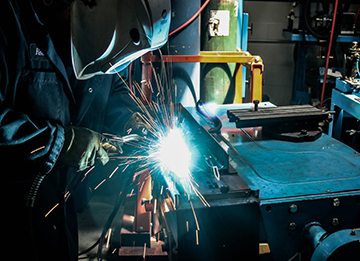
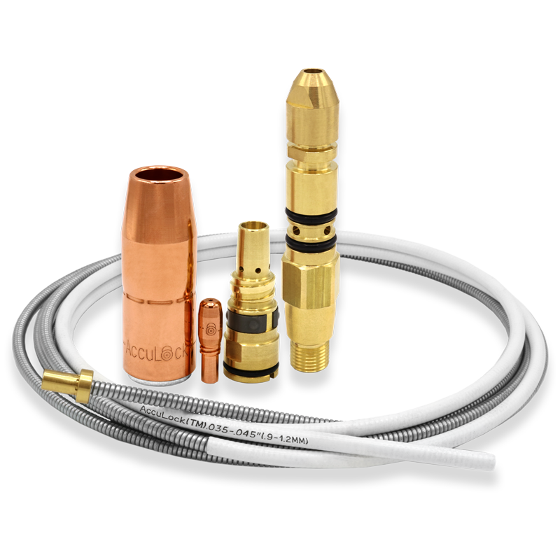
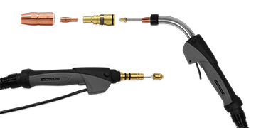
When MIG welding consumables aren’t properly installed or maintained, it can result in wire- feeding issues and weld quality problems. Troubleshooting and correcting these challenges can cost hundreds of dollars — and hours per day — in a manufacturing operation. As the industry faces a shortage of skilled welders and those entering the profession have less experience, it may be more common for welders to incorrectly install MIG gun consumables and liners. Consumables that simplify the installation process can help eliminate errors, reduce downtime for changeover and troubleshooting, and decrease costs. Learn how new consumables available in the marketplace can help address wire-feeding problems and the role they play in maximizing throughput and productivity. Not addressing poor consumable performance can result in, among other problems, lower-quality parts and expensive rework. Wire-feeding issues are some of the most common complaints in the welding industry. Often, improper trimming or installation of the MIG gun liner is the cause of these problems. As with other consumables, the MIG gun liner wears out over time and must be changed periodically. Typically, replacement liners are longer than necessary and must be trimmed appropriately for the style and length of the MIG gun. Trimming the liner to the proper length can be difficult. In some cases, the welder may change the liner without taking the time to complete the proper steps of installation or may not know the proper steps. This can result in a host of problems. A liner that is cut too short can lead to the issues a lot of welders experience: wire chatter, erratic arc and burnback. A too-long liner, which happens less frequently, results in a tight fit and can cause the wire to weave and curve as it feeds through the gun. If the operator continues to weld without diagnosing the cause of any of these problems, it may result in bad welds that require rework or result in scrap. It seems to be common in the industry that welders typically change the contact tip at the first sign of trouble with the welding gun, and this may help for a short-term fix. But if the liner is the root cause, the problem will repeat itself, leading the welder to use more tips than if a correctly trimmed liner was installed. This increases costs due to wasted consumables and downtime for changeover. In some operations, welders don’t install or trim liners. Instead, MIG guns are taken to a maintenance department whenever a liner must be changed. This adds downtime and costs and decreases throughput in the operation. Solutions that are designed to address liner trim length errors and poor wire feeding can reduce troubleshooting, downtime and rework — ultimately saving money. The AccuLock™ S consumables system from Bernard® take the guesswork out of liner trimming and installation in semi-automatic welding operations. The system offers an error-proof liner replacement process that eliminates measuring and incorrectly trimming liners. In contrast to most MIG gun liners that load from the back of the gun, AccuLock S liners load through the neck at the front of the gun. The liner is then locked and trimmed flush with the power pin at the back of the gun, which eliminates the need to measure. This design also eliminates doubt about proper liner length — and the time spent troubleshooting liner trimming issues — because operators can simply look at the back end of the gun to see that the liner is correctly trimmed and in place. With traditional MIG guns, welders can’t see if a liner is cut too short, since the end of the liner that’s been trimmed is hidden under the nozzle and gas diffuser. A welder would have to remove all the consumables to see the liner inside the gun. In addition, the system optimizes wire feeding because the liner is locked and concentrically aligned to both the contact tip and the power pin without the use of fasteners. Capturing the liner at both ends of the gun keeps the liner from extending and contracting based on gun position — and it allows for a flawless wire-feeding path. Typically, the longer the welding gun, the more the cable bends and twists. Even when a traditional liner is perfectly cut and installed, the liner gets pushed forward and back inside the gun as it’s used, since the liner is affixed at the back end of the gun but free floating at the front end of the gun. This liner movement can result in wire chatter and erratic arc. When the liner is affixed at both ends of the gun, as with the AccuLock S consumables system, welders are assured the liner won’t pull back, or push into the contact tip — allowing for smooth, uninterrupted delivery of the wire to the weld pool. And because the liner is concentrically aligned with the contact tip, it creates less mechanical wear on the tip’s interior diameter, possibly leading to longer life by reducing the risk of keyholing associated with misaligned liners and contact tips. Reducing keyholing also lessens the opportunity for an erratic arc, excessive spatter and burnback, all issues that shorten contact tip life. Additional features of the new consumables system also contribute to optimized MIG gun performance: Cool, connected contact tip: Sixty percent of the AccuLock contact tip is buried in the gas diffuser to protect it from heat damage. As the shielding gas flows through the gun, it cools the contact tip tail inside the gas diffuser, which helps reduce heat and wear. These features differ from traditional tips that screw onto the gas diffuser with little to no portion of the contact tip exposed directly to the shielding gas as it exits the diffuser to the arc. A tapered design of the consumables tightly locks the conductive parts together to minimize electrical resistance and further reduce heat buildup. Versatile nozzle: A patent-pending nozzle design allows operators to choose thread-on or slip-on — with the same nozzle part number. Typically, nozzles are either thread-on or slip-on style, a choice that often comes down to welder preference. A thread-on nozzle is locked in, while a slip-on nozzle can be adjusted to different heights and easily pulled off. With AccuLock S consumables, the same nozzle can be used as a slip-on or thread-on nozzle, and the change is determined by using a different diffuser. This allows operations to greatly simplify their consumables inventory and changeover, with fewer parts to manage. In addition, a steel retaining ring and friction lock on the diffuser help prevent the nozzle from unthreading or loosening when it’s threaded on. This also helps eliminate the potential for gas leaks at the back of the nozzle or insufficient gas coverage of the weld — a common occurrence when traditional thread-on nozzles loosen over time. Coarse threads: The AccuLock contact tip features coarse threads, making it less likely to become cross-threaded and also requires fewer turns to install or remove — speeding up tip replacement. One full turn disengages the contact tip from the diffuser. Significant time and money can be spent troubleshooting weld quality problems and wire- feeding issues, such as erratic arc, bird-nesting and burnback. In addition, many welding operations are dealing with increasing welder retirements and turnover, which can increase troubleshooting time associated with less experienced welders installing consumables. The AccuLock S consumables system is designed to eliminate liner trimming errors and optimize wire feeding to help operations reduce downtime, costs and rework — maximizing throughput and efficiency.
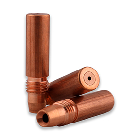
Optimizing the robotic weld cell helps improve productivity, allowing a manufacturing facility to save time and money. It can be especially beneficial in applications that use pulsed gas metal arc welding (GMAW-P), a process that results in rapid wear to the welding gun’s front-end consumables. While the choice of contact tip for the GMAW gun may seem like a small factor in the entire operation, consider how much time it takes for an operator to enter the weld cell and change the contact tip — and how many times per day the tip is changed in most robotic welding operations. For example, copper contact tips are changed on average four times per shift. In a three-shift operation averaging 10 minutes per tip change, that equates to spending two hours per day changing contact tips. What else could a welding operator be doing with this time to create value in the manufacturing operation? There are contact tip innovations that help significantly reduce the downtime spent on changeover — time that can be spent on other tasks in the operation, such as increasing production up-time. In addition, when the operator spends less time in the weld cell, it reduces the potential of health and safety incidents and the possibility of weld quality issues through altering weld settings and parameters such as tool center point. For these reasons, it’s important to consider the total cost of ownership when selecting the right contact tip for a robotic welding operation. As more manufacturing applications use thinner, lighter and more corrosion-resistant materials to meet industry demands, this increases the use of GMAW-P processes, which offer benefits for welding thin-gauge materials. Pulsed waveform technology continues to develop, offering faster travel speeds, reduced spatter levels and high weld quality in many robotic applications. However, pulsed processes typically require a higher frequency of contact tip changeover due to the energy of the process. Faster contact tip deterioration is caused by peaks in pulse waveforms where the energy/heat is five times greater than in traditional constant voltage (CV) GMAW. Because of this, arc erosion is a common failure for contact tips in GMAW-P. Contact tip failure increases an operation’s costs, due to the increased frequency of downtime related to tip changeover. A new contact tip design has resulted in tips with improved resistance to arc erosion that last much longer in pulsed welding. Contact tips made from copper or copper chrome zirconium are commonly used in many welding applications. However, adoption of a GMAW-P process can double contact tip replacement frequency and related downtime when using copper or chrome zirconium tips. A new innovative technology on the market today can significantly extend the time between contact tip changeover, thanks to a combination of proprietary materials and tip design. HDP contact tips from Tregaskiss last more than 10 times longer than copper or chrome zirconium tips, allowing operations to go from changing contact tips two to four times each shift to only changing the tips once every third shift or longer. HDP contact tips are engineered to resist wear better than other materials and designs previously used for contact tips, providing increased resistance to arc erosion in pulsed welding, as well as spray transfer and CV GMAW. The precise fit between the tip and the wire also results in good arc stability to help produce high-quality welds, and because the degradation of welding current from the power source to the contact tip is reduced, it provides a truer representation of the pulsed waveform program. The tips currently come in .035, .040 and .045 sizes and can be used with standard nozzles and TOUGH LOCK® retaining heads as well as with air-cooled guns or water-cooled guns. HDP contact tips can be used with Tregaskiss guns, as well as guns from other MIG welding gun manufacturers. Because the tip bore is sized so tightly to the welding wire, it’s best to use the HDP Contact Tip with good-quality welding wire that has a large cast. A high-quality wire typically has a consistent wire diameter, which promotes better feeding and optimized performance. Typically, operations conduct contact tip changeovers on a preventive maintenance schedule to avoid unplanned downtime in the manufacturing process. The necessary frequency of contact tip changeover varies based on many factors including application, wire type and quality, waveform and base material. Many robotic welding operations have 100 welding arcs or more and run three shifts per day. In robotic welding operations, copper tips are changed on average four times per shift — or 12 times per day. Chrome zirconium tips are changed about half as often, or six times per day. A scheduled contact tip change typically takes 10 to 15 minutes to complete. Compare this to real-world results from several manufacturing operations using HDP contact tips. For example, one manufacturing operation converted to HDP contact tips in a solid wire GMAW-P application. The operation produces 600 parts per shift, and the previous chrome zirconium contact tip required changeover every 60 to 80 parts — or about 10 times per shift. In the company’s trial, one HDP contact tip was still running after 2,500 parts under the same parameters. Another manufacturing operation running a standard GMAW process tried HDP contact tips on a line of 18 robots. Where previous contact tip usage for the operation was 216 per day — or about 1,500 tips per week — one HDP contact tip lasted an entire week on each cell, totaling 18 tips per week. In addition to the significant productivity gains the new contact tip design provides, there are other benefits for arc stability, productivity and operator safety. Reduced frequency in contact tip changeover not only increases throughput while saving time and money due to downtime, it also reduces the risk of safety incidents, since every time an operator enters the weld cell it increases the risk of injury. Also, each time someone touches the welding gun, there is the risk putting it out of alignment. The less frequently an operator must enter the cell, the less chance there is for human error that can disrupt tool center point that reduces part quality. Frequently changing the contact tip can cover up other issues within the weld cell. When the contact tip is changed less often, other issues such as wire feeding problems, wire routing or a loose ground can come to the forefront. With standard contact tips, changing the tip out is often the first go-to fix when there is a problem in the weld cell — even if something else is the root cause. With a longer-lasting contact tip that is not changed as frequently, other issues that may not have been noticed before can now be fixed to improve the overall efficiency of the weld cell. It’s important to consider total cost of ownership when evaluating contact tips and other consumables. The upfront cost of a contact tip is just one factor in total overall costs. A longer-lasting contact tip may be more expensive upfront, but it can provide significant payback in time and labor savings and reduced downtime. In considering a switch in consumables, an operation should also be sure there is time to conduct a trial, which should always be part of changing the type of consumable or contact tip. The numbers will often speak for themselves when vetting the option and analyzing return on investment. An operation may think the welding process is optimized, but that may not be the case if operators must frequently enter the weld cell to change the contact tip. As manufacturing operations look for ways to improve production efficiency and throughput in automated welding, choosing the right contact tip for the gun is one solution. A contact tip designed to provide significantly longer tip life saves time and money in necessary changeover and reduces the frequency of people entering the weld cell. New contact tips on the market can last days in GMAW-P applications compared to standard copper tips that may only last a few hours. *Other parameters: 450 ipm wire feed speed, 40-45 ipm travel speed, 90/10 mixed gas, 240-260 average amps on a Tregaskiss robotic MIG gun with a 22-degree neck.
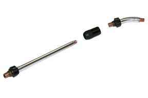
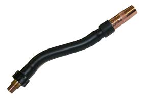
Optimizing MIG welding gun performance in specific applications can be a matter of choosing different components for the gun. Selecting the right MIG gun neck improves access to the weld joint, increases operator comfort and can reduce costs in the operation. The biggest factor when choosing a gun neck is to ensure it provides proper access and visibility to the work. In some applications, the weld joint may be difficult to reach, or it may require you to reach down into a groove. A gun neck should provide optimal access to the weld joint — so you can do your best work while maintaining proper ergonomics. In addition to joint accessibility, several other factors play a role in the decision, including the welding process and parameters, the welder’s height and whether the gun has a curved or straight handle. Keep the following considerations in mind to choose the right MIG gun neck for your application. Certain welding processes and filler metals generate much greater heat during welding, so take that into account when choosing a gun neck. Pulsed welding processes, the use of metal-cored wires and even certain materials, including stainless steel and aluminum, all generally create more heat during welding. The welding parameters — including amperage, volts, joint configuration and distance from the welder to the joint — also impact the amount of heat produced and felt by the welder. In applications with high heat, a standard short gun neck can cause the heat to radiate through the glove and into the welder’s hands. It’s recommended to use a longer gun neck in these situations to keep the heat farther away. Another good rule of thumb to remember is the larger the wire diameter being used, the longer the gun neck should be. Standard necks for MIG guns are available in a range of options, with varying angles and material types. • Aluminum armored necks can withstand abuse and offer outstanding heat dissipation. They are typically available in fixed and rotatable styles, and some models require no tools to rotate. These necks, which come in 30-, 45-, 60- and 80-degree angle options, are a good all-purpose choice for many welding applications. • Black polymer armored necks, available in a 60-degree angle, contain a thick copper wall with a conductor tube interior, so they don’t radiate or reflect heat as quickly. This insulation from the heat makes them a good choice for higher-amperage welding applications. Be aware that black polymer armored necks can become brittle and break since the high temperatures, over time, can break down the exterior tube. Choosing between these standard neck options is often a balance of application requirements and welder preference. The same is true for choosing a neck angle. The style of the gun handle, however, is also a determining factor in selecting the right neck angle. When using a curved handle, it’s often more comfortable to use a 60-degree neck than a 45-degree neck. With a straight handle, a 45-degree neck is typically better suited due to natural hand placement. A welder’s height also impacts proper neck angle: A taller welder may want to use a 60-degree neck, while a shorter welder may prefer a 45-degree neck for comfort. A neck coupler is an accessory that allows a flex neck to be added to the top of an existing standard neck. This can be used when a longer neck with flexibility is needed to get into hard-to-reach areas. to-reach or narrow areas. Some flex necks have a bend radius up to 80 degrees. These necks are typically available in 6- and 8-inch lengths for straight and curved handles. Because flex necks can be changed, rotated or bent without tools, this saves time and labor. In applications where a standard neck can’t provide proper access to the weld joint, consider using a flex neck, which can be bent into a desired shape or angle to access hard-to-reach areas. Some flex necks can also be used with an easily removable jump liner for quick changeover. Jump liners replace only the most commonly worn and clogged liner area in the neck bend, to reduce downtime for liner changeover. A jump liner connects the standard liner at the back of the neck and runs through the neck up to the contact tip. Because a jump liner allows for quick and easy neck change-out, the gun can be easily adapted to fit multiple applications. For example, flex necks and rotatable necks are frequently used in shipbuilding. A welder may be in the ship’s hull and need multiple neck styles to access different weld joints. Instead of bringing several welding guns to the work area, a jump liner allows the welder to quickly unscrew one neck and thread another one on without changing or trimming the liner. An operation can also reap cost savings, since jump liners are less expensive than standard liners and quicker to install. When available standard or flex necks don’t provide proper weld joint access, specialty necks can be created. Multiple lengths and bends are available for limited access positions and improved operator comfort. These necks are specially designed by manufacturers to fit the specifications of the application. Because producing a quality weld hinges on optimal access to the joint, in some cases a custom neck can provide the best accuracy and results. Many neck options are available for MIG welding guns, including rotatable, flex, various bend angles and lengths, neck couplers and custom necks. Choosing the right style can improve your comfort and maneuverability — especially with hard-to-access welds. When you’re unable to reach your weld joints comfortably using a standard neck, consider adding a specialty or custom neck to your toolkit.
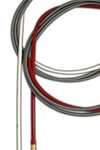
A MIG gun liner is an important consumable because it can make a significant difference in gun performance and the time and money an operation spends in unplanned downtime. Proper installation of the liner is critical to its ability to guide the wire through the welding cable and up to the contact tip. Improper liner installation — which includes trimming the liner too short or having a liner that is too long — can result in a number of problems, such as birdnesting, wire feeding issues and increased debris in the liner. These issues can result in costly rework and operator downtime for maintenance and repairs, which impacts productivity. Also, wasted wire due to issues like birdnesting can drive up costs for a company. The installation process is somewhat similar for all types of MIG gun liners, with some variations. Here are some general steps to consider when installing a new MIG gun liner. There are some variances in the installation process, depending on the type of liner being used. Follow these steps when installing a front-loading liner. The only difference in this installation process is that there is no receiver in the back of the power pin. The receiver is built into the module pin. The installation process also varies when retrofitting a gun from a conventional liner to a front-loading liner. Here are a few additional things to remember: The quality of the liner also can impact welding performance, productivity and operator downtime, so it’s important to buy quality liners from a trusted manufacturer. Choosing the correct size of liner for the wire being used is another way to help maximize performance. While liners may seem like a small part of the welding operation, it’s important to be mindful of the impact they can have on quality, performance and costs. Liners perform a vital function in the MIG welding process, and the proper installation and maintenance of liners can help reduce costly rework, operator downtime and wasted wire.
Customer Testimony | Graham Corporation Adopts Bernard MIG Guns and Consumables
Graham Corporation Adopts Bernard MIG Guns and Consumables
Customer Testimony | Bernard MIG Welding Consumables Save Time and Last Longer
Bernard MIG Welding Consumables Save Time and Last Longer
Customer Testimony | Bernard Replaceable MIG Gun Parts Save Money, Improve Performance
Bernard Replaceable MIG Gun Parts Save Money, Improve Performance
Customer Testimony | Welding students in Tulsa benefit from Bernard MIG guns and consumables
Welding Students in Tulsa Benefit from Bernard MIG Guns and Consumables
Customer Testimony | Blinn Instructors Choose Bernard MIG Guns and Consumables for Dependable Welding Equipment
Blinn Instructors Choose Bernard MIG Guns and Consumables for Dependable Welding Equipment
Video | Bernard Centerfire Changing Consumables Challenge
Bernard Centerfire Changing Consumables Challenge
Video | Bernard AccuLock S Consumables for the Inexperienced Welders
Bernard AccuLock S Consumables for the Inexperienced Welders
Video | Bernard AccuLock S Consumables for Better Productivity
Bernard AccuLock S Consumables for Better Productivity
Animation | Bernard AccuLock S Consumables No Measuring Required
Bernard AccuLock S Consumables | No Measuring Required
Animation | Bernard AccuLock S Consumables Dual Locked Liner
Bernard AccuLock S Consumables | Dual Locked Liner
Video | Tregaskiss QUICK LOAD Liner Replacement Race
Tregaskiss QUICK LOAD Liner Replacement Race
Animation | Tregaskiss QUICK LOAD Liner AutoLength System
Tregaskiss QUICK LOAD Liner AutoLength System Animation
Video | Tregaskiss AccuLock R Consumables for Better Throughput
Tregaskiss AccuLock R Consumables for Better Throughput
Video | Tregaskiss AccuLock HDP Contact Tips
Tregaskiss AccuLock HDP Contact Tips
Animation | Tregaskiss AccuLock R Consumables
Tregaskiss AccuLock R Consumables Animation
Selecting Contact Tips for Robotic Welding
Selecting Contact Tips for Robotic Welding
The job of the contact tip is to transfer the welding current to the arc and guide the welding wire as consistently as possible. If either of these two factors degrade, the overall welding process also degrades, affecting quality.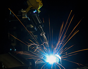
fuse in the fuse box that is your robotic
welding cell. But this small fuse can have
a big impact on productivity.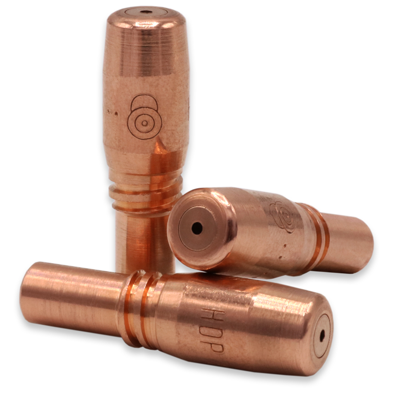
Once you understand the types of contact tips available, there are numerous factors to consider when choosing the right tip for your application. Here are some common mistakes operations make when choosing contact tips so you can avoid the same pitfalls:
If contact tips are being removed proactively even when there is no keyholing, burnbacks or erratic arcs, there could be potential to get more life out of contact tips.
It’s important to look beyond the purchase cost and consider the big picture to best evaluate the potential productivity, as well as weld quality and efficiency gains of certain contact tips. The benefits can be especially significant in robotic welding applications, where regular contact tip changeovers can be greatly reduced.AccuLock R Consumables Reduce Downtime in Robotic Welding
AccuLock R Consumables Reduce Downtime in Robotic Welding
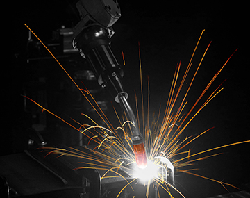
Consumable challenges
A new consumables solution

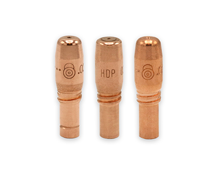
Making the change
Selecting the Right MIG Welding Consumables
Selecting the Right MIG Welding Consumables
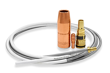
Selecting contact tips
Welding nozzle options
MIG gun liner selection
This article is the third in a three-part series discussing how configuring a MIG gun can improve the welding operation, as well as what to consider in the process. Read article one, Configuring a MIG Welding Gun for Your Application and article two, How to Choose MIG Welding Gun Parts.Common Problems With MIG Welding Consumables and How to Fix Them
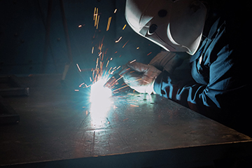
Making sense of welding nozzles
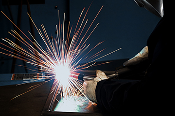
Avoiding contact tip downfalls
Pay close attention to the contact tip material to avoid premature failure. Consider these options:
Getting it straight about liners
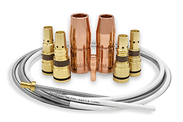
Final considerations
MIG Welding Consumables Reduce Wire Feeding Issues and Downtime
MIG Welding Consumables Reduce Wire Feeding Issues and Downtime
The cost of poor consumable performance
Error-proof liner replacement
Optimize wire feeding
Maximize performance and life
Reduce wire-feeding and weld quality issues
New HDP Contact Tips Provide Robotic Pulsed MIG Welding Benefits
New HDP Contact Tips Provide Robotic Pulsed MIG Welding Benefits
Demands of GMAW-P
Contact tip advancements
Significant productivity gains

Additional benefits
Return on investment
Be sure to look at the big picture in terms of productivity and efficiency improvements for the entire operation.Improve productivity and efficiency
What MIG Gun Neck is Right for You?
What MIG Gun Neck is Right for You?
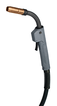
Feeling the heat
Standard necks
Flex necks
Specialty necks
Final thoughts
Steps for Proper MIG Gun Liner Installation
Steps for Proper MIG Gun Liner Installation
Step-by-step installation
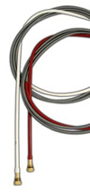
That way, once all of the consumables are back on at the front of the gun, the wire is already in the gun and ready to be pulled through.
Installing a front-loading QUICK LOAD Liner
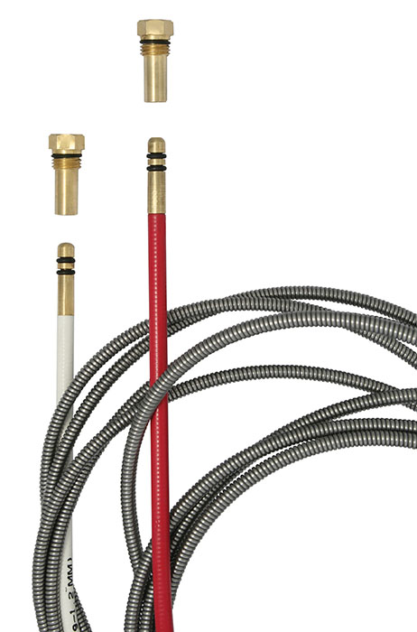
1. Unravel the liner (which comes coiled) and stick the brass end — the end that goes into the receiver at the back of the gun — over the wire and through the neck.
2. Feed the liner through the front of the gun using short strokes, to avoid kinking the liner. The front-loading liner will click or snap into place once it hits the receiver in the power pin.
3. Once that is complete, put the liner gauge on top of the liner and follow the standard installation steps above.Installing a front-loading liner with the spring-loaded module
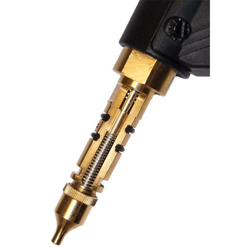
Retrofitting a gun
Proper liner installation can help optimize performance


