Tips for Proper Liner Installation to Help Optimize MIG Gun Performance
MIG gun consumables are often one of the most overlooked portions of the welding operation. However, choosing the right consumables, and using and maintaining them properly can make a significant difference in gun performance and weld quality.
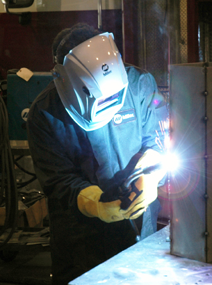
Consumables comprise the front-end part of the gun and include the nozzle, retaining head, contact tip and liner. A MIG gun liner spans from the front of the gun through to the power pin and is the conduit through which the welding wire feeds. Proper installation of the liner is critical to its ability to guide the wire through the welding cable and up to the contact tip.
Improper liner installation — which includes trimming the liner too short or having a liner that is too long — can lead to a number of problems, such as birdnesting, wire feeding issues and increased debris in the liner. These issues can result in costly rework and operator downtime for maintenance and repairs, which impacts productivity. Also, wasted wire due to issues like birdnesting can drive up costs for a company.
Various types of liners for the job
There are several liner types available for semi-automatic applications. Choosing one is often up to the preference of the welding operator or maintenance personnel. Each type has advantages and disadvantages for specific applications and can offer compatibility with varying gun styles and sizes.
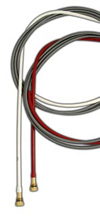
Conventional liners are installed through the back of the gun and are longer than the cable, often up to 25 feet long. These are frequently used in the industry; so many welding operators are familiar and comfortable installing this type of liner.
A disadvantage of conventional liners is the lengthy changeover process. In the cases of liner replacement, this may require the welding operator to climb over robotic tooling or transfer systems to remove the gun from the wire feeder. In the case of semi-automatic MIG guns that are connected to boom-mounted feeders, the welding operator may need to climb several feet into the air to change liners. Another disadvantage of conventional liners is that they can’t account for changes in length as the cable grows and shrinks with twisting (due to the fact that MIG gun cables are wound in a helix pattern). This can lead to the liner not being seated properly inside the retaining head, resulting in wire chatter and feeding issues.
Front-loading liners are, as the name implies, installed from the front of the gun. This offers timesaving advantages, since the welding operator does not have to leave the front of the gun for changeover, which can reduce downtime. Front-loading liners have the same disadvantage as conventional liners, since they can’t grow or shrink with the cable as it twists and moves. Jump liners are a type of front-loading liner. Whereas standard front-loading liners are full length, jump liners are shorter — often about 1 foot long — and replace only the part of the liner that wears the quickest, typically at the neck of the gun.
Front-loading liners that have a spring-loaded module inserted into the power pin allow for up to 1 inch of motion as the cable twists and the liner moves forwards and backwards. This type of liner reduces the opportunity for gaps at the front of the gun and helps to compensate if the liner is trimmed too short.
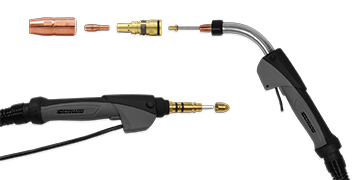
Systems like the Bernard® AccuLock™ S Consumables for semi-automatic MIG guns feature a nozzle, contact tip, diffuser and liner design that work in conjunction to provide error-proof liner installation and replacement. The AccuLock™ S Liner loads through the neck at the front of the gun, then is locked and concentrically aligned to both the contact tip and power pin. The liner is then trimmed flush with the power pin — no measuring required — and reinstalled to the wire feeder. This eliminates gaps and misalignments at the front and back of the MIG gun liner for flawless wire feeding.
Step-by-step installation
The installation process is somewhat similar for all three types of liners, with some variations. Here are some general steps to consider when installing a new MIG gun liner.
These steps are the same for both semi-automatic and robotic MIG guns:
1. Before removing the consumables, make sure the gun is straight and the cable is flattened. This makes it easier to feed the liner all the way through.
2. Trim the wire at the front of the gun to remove the bead of molten wire that often forms after welding.
3. Remove all of the front-end consumables so the liner can be fed through the gun.
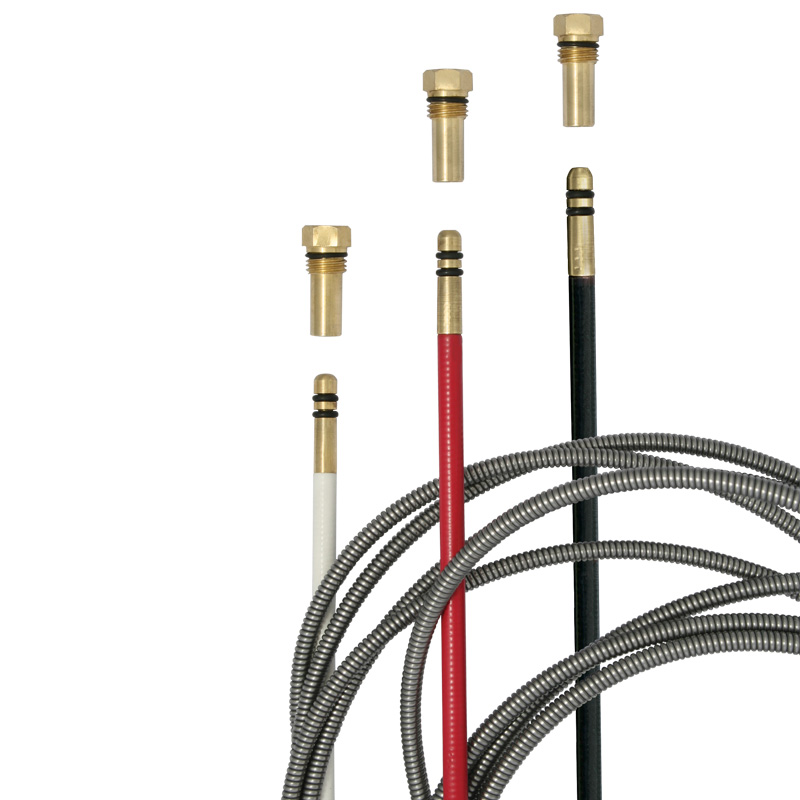
4. For a conventional liner installation, remove the power pin from the feeder at the back of the gun and cut the wire. This allows the wire and a conventional liner to be removed from the back of the gun.
5. If using a conventional liner, feed the liner through the back of the gun, threading it into the power pin. Reinsert the power pin back into the feeder, and feed a few inches of wire through the back of the power pin. That way, once all of the consumables are back on at the front of the gun, the wire is already in the gun and ready to be pulled through. (See below for variations for front-load liners and front-load liners with spring-loaded modules)
6. Because the liner is longer than the gun assembly (designed to accommodate varying gun and cable lengths), there will be a foot or so of liner sticking out the front of the gun, so it’s necessary to trim the liner to the correct length. Conventional liners and front-loading liners often come with a plastic liner gauge that has a 3/4-inch stick-out. This can be fed over the top of the liner and pressed up flush against the neck, so the liner can be trimmed to the end of the gauge.
7. Hit the trigger, to pull the wire up, and at the same time purge the gun with shielding gas.
There are some variances in the installation process, depending on liner type. Here are some differences to note:
• When installing a front-loading liner, unravel the liner (which comes coiled) and stick the brass end — the end that goes into the receiver at the back of the gun — over the wire and through the neck. Feed the liner through the front of the gun using short strokes, to avoid kinking the liner. The front-loading liner will click or snap into place once it hits the receiver in the power pin. Once that is complete, put the liner gauge on top of the liner and follow the standard installation steps above.
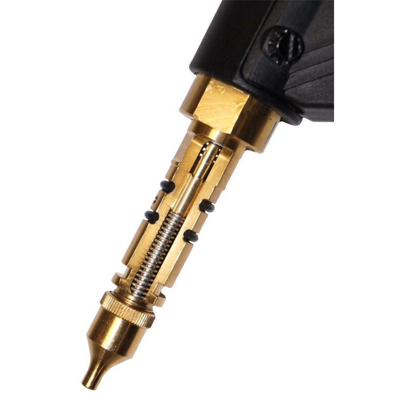
• When installing a front-loading liner with the spring-loaded module, the only difference is that there is no receiver in the back of the power pin. The receiver is built into the module pin. While feeding the front-loading liner into the gun using short strokes, the liner will engage with the receiver inside of the module’s power pin. When this happens, the welding operator can feel the liner spring back toward the front of the gun. This is a good sign, because it means the liner is properly engaged.
Place the liner trim gauge over the front-loading liner until it is flush against the neck. Push the liner back into the gun until it bottoms out against the spring-loaded module, then trim the liner flush to the end of the liner trim gauge. After trimming, remove the liner trim gauge and release the liner. Note that the liner will spring back and stick out of the neck by approximately 1-3/4 inch, which is normal, as installing the consumables will compress the liner into its proper position.
The installation process also varies when retrofitting a gun from a conventional liner to a front-loading liner, or when completing a liner changeover, as compared to installing a new liner in a new gun. When it’s not the first time the liner is being installed, there are a few additional things to remember:
• When retrofitting a gun from a conventional liner to a front-loading liner, the first installation will be from the back of the gun, since a receiver is needed on the back in order to accept the front-loading liner.
• After following all of the standard steps above and removing the conventional liner and wire from the gun, install the end of the front-loading liner with the O-rings on it into the receiver and unravel the liner. Feed the front-loading liner in, just as with a conventional liner, through the back of the gun, and thread the receiver into the power pin.
When installing a liner as part of the AccuLock S Consumables Series, follow the same steps as when installing other types of liners, removing the front-end consumables and old liner. Then replace the new liner through the neck, and with the gun lying straight, push the liner through until the brass liner lock bottoms in the neck. To lock and center the liner, reinstall the gas diffuser and nozzle, and place the power pin cap over the liner, torquing it to 60 in-lbs (7Nm). Then simply trim the liner flush with the power pin at the back — no need to measure the liner.
Proper liner installation can help optimize performance
The quality of the liner also can impact welding performance, productivity and operator downtime, so it’s important to buy quality liners from a trusted manufacturer. Choosing the correct size of liner for the wire being used is another way to help maximize performance. While liners may seem like a small part of the welding operation, it’s important to be mindful of the impact they can have on quality, performance and costs. Liners perform a vital function in the MIG welding process, and the proper installation and maintenance of liners can help reduce costly rework, operator downtime and wasted wire.
Additional Resources


