
From Consumables to Cables:
Troubleshooting Robotic Welding
system, it is critical to identify the problem
as quickly and accurately as possible. Look
first at the variables that have most recently
changed, as these may be the culprits.
Companies invest in robotic welding to increase throughput and profitability — so there is a lot at stake when something goes wrong in the process. Unplanned downtime for troubleshooting problems in the weld cell can add up to significant costs. In some cases, companies may hire more employees to address production issues or create workarounds in an effort to mitigate issues that are slowing down or stopping the robotic welding process.
Most often, when a problem occurs with a robotic welding system, it’s valuable to ask first: What has recently changed in the process? Has the operator recently reprogrammed the robot? Or was the system restarted after a long shutdown? What about the consumables — has anything changed with them and have they been installed correctly?
Quite often, looking at the most recently changed variable in the process can help narrow down the point of trouble. The issue may be something as simple as a loose or cross-threaded contact tip or more complex like an incorrect tool center point (TCP). Whichever the case, it’s important to have good troubleshooting skills to help narrow down the focus and get the robotic welding system back on line sooner. It’s also important to have the right equipment, including welding consumables.
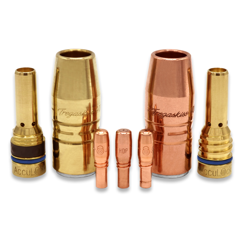
Poor Consumable Performance and/or Premature Failure
The longevity of consumables — nozzles, contact tips, diffusers and liners — in a robotic welding application depends in part on the material being welded, the welding parameters and the consumable style and material. High-amperage, high-deposition-rate applications, for example, tend to be harsher on consumables than those with lower amperages. Pulsed welding operations are also very harsh on consumables, particularly contact tips. Using a contact tip with a hardened insert can help the component last longer — 10 times longer, in fact — by better resisting electrical and mechanical wear.
Still there can be multiple causes for poorly performing consumables and/or premature failure.
For instance, a cross-threaded contact tip can lead to quality issues due to poor TCP, lack of fusion or poor weld penetration. It can also cause the contact tip to keyhole or wear unevenly. To prevent this, look for a contact tip with a long tail that concentrically aligns the contact tip within the gas diffuser before the threads engage. This design, along with coarse threads on the contact tip, helps prevent cross-threading. Such easy-to-install consumables are ideal for companies who may have less experienced welding operators on staff — and they can minimize downtime for troubleshooting incorrectly installed contact tips.
A loose connection between consumables can be the culprit. Loose connections increase electrical resistance, causing the consumables to generate additional heat that can shorten their lifespan and/or cause them to perform poorly. Be certain to tighten consumables properly upon installation, per the manufacturer’s instructions, and check them periodically during routine pauses in welding. For companies that weld thick materials or long welds, it is especially important to make sure that consumables are tightened properly, as the rework for quality issues caused by poorly performing ones can generate much more costly rework than an application that produces multiple smaller parts.
Issues with the contact tip are also not uncommon, particularly burnbacks. These are often the result of a liner being trimmed too short. Welding operators should follow the manufacturer’s instructions for trimming and installation, and when possible use a liner gauge to confirm the correct liner length.
Contact tips designed with greater mass at the front and those that are buried further within the gas diffuser can help withstand heat better to prevent premature failure. Consumables with tapered connections also provide excellent conductivity so there is less heat buildup that could cause additional wear. When contact tips last longer, there is less need for downtime for changeover and less risk of installation errors.
If the robotic welding system utilizes a nozzle cleaning station (also called a reamer) and consumable issues occur, such as spatter build-up, check to see that this equipment is working properly. Also be certain that the reamer is cleaning the consumables at a frequency that is appropriate for the application. It may be necessary to increase the frequency of cleaning and/or anti-spatter spray application throughout the programmed welding cycle.
If weld defects — like porosity or lack of fusion — are occurring frequently, it might also be indicative of an issue with the consumables. Check to see that the contact tip and nozzle are free of dirt and debris. Replace them as necessary.
Premature Cable Failure
Premature power cable failure can occur in both through-arm robotic welding systems, where the cable feeds through the arm of the robot, or in standard robotic welding systems (also referred to as over-the-arm). The power cable may become kinked or worn, causing the failure — or in extreme cases, it may even snap.
If any of these situations occur, it is important consider the path the robot is programmed to follow, as well as the length of the power cable being used. First, be certain that the robot’s movements have not been programmed to be too fast or abrupt. Aggressive movements can cause the power cable to snap. Or in some cases, it may cause it to flop around, allowing the power cable to rub against the robot or tooling, or catch on components — both instances that can lead to premature failure.
Also, check that the power cable being used is not too short for the application or too long. If it is too short, the power cable will stretch beyond its capacity during routine robotic movements, leading to greater wear. Conversely, if the power cable is too long it may be prone to kinking or becoming pinched by the robot’s arm.
Poor Wire Feeding

help extend consumable life. Should any
problems occur with the equipment,
check that the reamer is positioned
accurately and is applying the correct
mount of anti-spatter solution.
Poor wire feeding in a robotic welding application can lead to equally poor weld quality. Issues with the liner, including debris build-up, can often cause the problem. Be certain to change out the liner during routine maintenance to prevent debris build-up from the welding wires and the environment. Blowing compressed air through the liner also helps. Ideally, consider using a robotic MIG gun with an “air blast” feature, which blows the air through the liner during a scheduled time in the robotic program (for example, during a reaming or cleaning cycle).
An improperly functioning wire feeder — specifically the drive rolls — can also cause poor wire feeding. Over time, these components can become worn and may not guide the welding wire properly. Or the drive rolls may not be tightened correctly. Inspect the drive rolls for signs of wear and replace them as necessary.
Welding operators can also determine whether the drive rolls are the problem through a process of elimination. Namely, by conducting a “two finger” test — disengage the drive rolls, grasp the welding wire and pull it through the gun. It should be able to pull easily through. If it does then it’s possible that the drive rolls are the cause of the poor wire feeding. If the wire does not pull through easily, it indicates a problem outside of the wire feeder and drive rolls, such as debris in the liner or another such restriction within the robotic MIG gun. It may even be the result of having too small of a contact tip in place.
Welding operators should also look for kinks in the power cable, as these can also lead to wire feeding problems.
Poorly Performing Peripherals
Peripherals — in particular, reamers — can help companies optimize their robotic welding performance and extend the life of their consumables. If a welding operator notices that there is an excessive build-up of spatter on the consumables, however, it may indicate a problem with the reamer.
There are typically three reasons for a reamer to function poorly. The first relates to the taught position of the robotic MIG gun nozzle in relation to the reamer. That is, where the robot clamps to the reamer. The position should be exactly perpendicular to the cutting blade on the reamer. Any misalignment of the nozzle during cleaning could lead to partial cleaning of the nozzle and excessive spatter build-up. As a first step in troubleshooting, check that the taught position is correct.
Secondly, if using anti-spatter solution, check that the spray location is correct. Is the solution fully coating the inside of the nozzle? If not, adjust the location accordingly. The nozzle should be coated until it is slightly damp on the inside and the outside should be covered to within three-quarters of an inch from the bottom of the nozzle. And while it seems like an obvious troubleshooting step: Always be sure to check that there is anti-spatter solution in the sprayer!
Lastly, be certain the proper cutting blade is in place and that it is sharp.
Trouble with TCP
In addition to speed, one of the greatest advantages of a robotic welding system is the repeatability that it provides, and the subsequent quality of the welds. If a welding operator begins to notice inconsistent welds or welds that are off-location, it may be a problem with the TCP.
TCP is the focal point of a tool. In the case of a robotic welding system, it refers to the location of the robotic MIG gun and how it corresponds with the position of the welding wire in the joint (gun-to-work distance).
Most often, issues with TCP occur after a collision, during which the neck of the robotic MIG gun becomes bent. To rectify the problem, welding operators should use a neck-checking fixture or neck alignment tool to make sure the neck is bent to the proper angle. It is also important to check that the neck is installed correctly. If the neck isn’t fully seated, it may extend too far and lead to TCP problems. To protect against future issues, it may also be helpful to program a TCP check to verify the proper position.
Welding operators, however, shouldn’t assume that welds that are off-location are always caused by an incorrect TCP. In some cases, they can be the result of improper fixturing, fixturing that allows the part to move or a loose robot base. Or there may be a variation in the part itself.
To differentiate between a TCP problem and other problems that could cause off-location welds, first take the neck off the robot, implement a TCP check via the robotic program and verify that everything is on-location. If everything checks out properly, the problem is likely a part or position variation.
Final Considerations
When something goes wrong in a robotic welding system, it is critical to identify the problem as quickly and accurately as possible. Not only can swift troubleshooting ensure that the operation returns to producing quality, repeatable parts, but it can also help prevent unnecessary costs for replacing components that may not need replacing. Always start with the simplest solutions first and consider keeping a checklist for setup and maintenance procedures. Having a quick reference point can help facilitate the troubleshooting process by identifying potential variables that have changed during the course of routine operations.