Customizing Your GMAW Gun for the Job
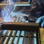
The heat and repetitive motions that accompany gas metal arc welding (GMAW) can take their toll. Customizing your GMAW gun to match your application, however, can make a big difference in improving your comfort, and gaining the best welding performance.
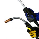
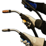
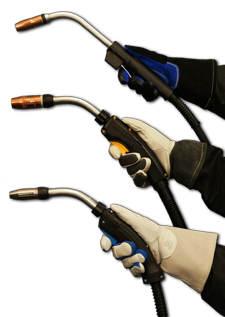
A GMAW gun’s trigger, handle, neck and power cable design all impact how long you can comfortably weld without experiencing fatigue or stress.
By ensuring your comfort, you lessen the chance of injuries associated with repetitive movement and reduce overall fatigue. To help, some manufacturers offer online systems to help you configure a gun to your exact specifications.
This article has been published as a web-exclusive on thefabricator.com. To read the entire story, please click here.
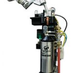
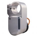
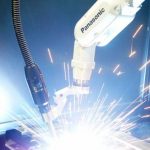
Peripherals — equipment that is integrated into the robotic welding process to make it more effective — can significantly boost the return on investment you achieve from your welding robot. And incorporating and operating peripherals successfully doesn’t have to be difficult. To help, it is important to understand how your peripherals are intended to function and employ some best practices for using them. All robotic welding systems require some form of collision detection to prevent damage to both the robotic MIG gun and the robot arm in the event of an impact. Impacts can occur when the robotic MIG gun collides with an incorrectly positioned work piece or out-of-position tooling, or when the gun strikes an item that has inadvertently been left in the welding cell. Some robotic systems incorporate robot collision detection software. Systems that do not have built-in collision detection, however, should always be paired with a clutch — an electronic component that attaches to the robotic MIG gun to protect it and the robot from heavy damage in the event of a collision. In some cases, you may choose to add a clutch to a system that utilizes collision software as backup protection for the robot. Always make sure the clutch works with the weight of the load created by the robotic MIG gun and front-end consumables. If the gun is not properly supported and the robot moves rapidly to another spot on the other side of the part, the extra weight can move the clutch out of its optimal position. If a clutch gets triggered from a collision, reset it by pulling it towards you and letting it snap back into position. After, be sure to check your tool center point (TCP) to ensure the robotic MIG gun is properly aligned for precise welding of the joint. If it is off center, validate that the clutch is in its home position. If you have robotic welding applications that require consistent welding wire stick-out — the distance the wire extends from the end of the contact tip — a wire cutter is a recommended peripheral. As the name implies, a wire cutter cuts the welding wire to a specified length or stick-out and also removes any balling at the end of the wire. Most wire cutters can cut a range of different types of welding wire, including stainless steel, flux-cored and metal-cored, usually up to 1/16-inch diameter. They can often be mounted on a nozzle station or used remotely as needed. In conjunction with a wire brake, the wire cutter can ensure that the stick-out remains consistent for robots with touch sensing capabilities that help locate the joint. Another key peripheral is a neck inspection fixture, which tests the tolerance of a robotic MIG gun’s neck to the TCP so you can re-adjust it after an impact or after bending due to routine welding. The advantage of adding a neck inspection fixture to a robotic weld cell is twofold. One, it ensures the neck meets the specifications to which the robotic welding system has been programmed and, once the tolerance has been determined, you can simply adjust the neck accordingly. This can prevent costly rework due to missed weld joints and can also prevent downtime required to reprogram a robot to meet welding specifications with an existing bent neck. Second, a neck inspection fixture can save you time, money and confusion when exchanging necks from one robotic MIG gun to another. Having this ability is especially advantageous if you maintain a large number of welding robots. You can simply remove a bent neck and change it with a spare that has already been inspected and adjusted, and put the robot back in service immediately. One of the most important peripherals you should consider for your robotic welding system is a nozzle cleaning station or reamer. A nozzle cleaning station removes spatter from the robotic MIG gun nozzle and clears away the debris that accumulates in the diffuser during the welding process. This helps lengthen the life of the robotic gun consumables, as well as the gun itself. A clean nozzle also reduces problems that could lead to rework and helps the robot create better quality welds. During installation, be sure your reamer is on a sturdy base or otherwise securely fastened and not moving around during the reaming cycle. Ideally, the nozzle cleaning station should be placed in close proximity to the welding robot so it is easily accessible when cleaning is necessary. You should program the reaming process to run in between cycles — either during part loading or tooling transfer — so it does not add to the overall cycle time per part. Always keep the covers on your reamer. The electronics within a reamer can be easily ruined by moisture from the atmosphere. Also, remember to use clean, filtered and lubricated air in your reamer. If “dirty” air goes into the reamer, it will clog up the valves. If you don’t have a lubricator installed on the reamer, use an alternative method to lubricate the air that goes through the motor. It is important that your reamer matches the diameter of the nozzle and that the blade does not hit the diffuser or nozzle when it goes through a ream cycle. Be sure you are using the right blade for the nozzle you have and that your nozzle is set at the correct depth within the jaws of the reamer. A reamer can be used by itself or in conjunction with a sprayer that applies an anti-spatter compound to protect the nozzle, diffuser and work piece from spatter. Make sure the nozzle is the correct height away from the spray block and that the duration of the spray is about a half a second. Too much anti-spatter compound can ruin the insulator on your nozzle, and can lead to unnecessary costs for replacement. The compound may also build up on the nozzle, the robot and the parts being welded, resulting in additional cleanup. Frequently check that the sprayer and sprayer head is free of debris; if spatter gets inside the sprayer head, it will cause the spray plume to be distorted, which will create inconsistent coverage. If you are using a multi-feed anti-spatter system, be sure you have a good quality hose, such as a urethane hose, and that it is protected from any spatter that may hit it and create a hole. Also, securely fasten the hose with clamps at every connection to prevent leaks. You may consider using a spray containment unit to capture excess anti-spatter compound. If so, weekly inspections are recommended; remove any spatter or debris that may have fallen to the bottom. Failing to do so can prevent the unit from draining, which will cause the containment unit to overflow and create a mess. The decision to invest in robotic welding equipment is significant. It requires time, knowledge and a trusted relationship with a robotic welding equipment manufacturer to find the right system. The same holds true for peripherals. Although these devices do add to the initial cost of automating, they can lead to measurable cost savings and profits in the long run. But remember, the goal in robotic welding is repeatability and increased productivity, and any additional equipment that can help achieve these results may be worth your investment.
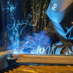
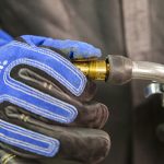
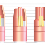
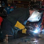
Implementing and operating a robotic welding system requires attention to detail to gain high productivity and consistent quality. It’s equally important to do whatever you can to protect your investment for the long term — from the robot to the MIG gun and more. In some cases, robotic peripherals are an additional means to help and can provide added safety, in the case of a clutch. As a safety device for your robotic MIG gun, a clutch attaches to the robotic MIG gun and protects it — and the robot arm — from damage. If the robot crashes, the clutch will send a signal back to the robot that alerts it to shut down. Not only does this help prevent further damage to the robotic arm, but it also protects your gun and your front-end consumables. While many newer robots are equipped with collision detection software that serves the same function as a clutch, older robots, which are still very commonly used, are not. Regardless of whether you’re operating a new or older robot, everyone knows your robotic welding system is only as good as the uptime it offers. It’s essential to keep as much arc-on time as possible. When selecting a clutch, you need to choose one that can hold whatever load is going to be on it. For example, if the front end of the gun is extremely heavy and requires significant air movement, some clutches may not be able to support it or may require an adjustment to their sensitivity settings. Also, look for obvious size constraints and make sure the clutch fits within your molding application and tooling. When setting up your clutch be sure to check your tool center point (TCP). Putting on a clutch should not significantly change the TCP. If it’s off, be sure to validate that the clutch is in its home position. Also, when replacing a clutch, make sure the TCP is within specifications. Similarly, always reset the clutch to its home position and recheck the tool center point after a crash. If the tool center point is off, look first to make sure no other damage occurred to another component during the crash. It could indicate that the neck bent out of position, for example, and needs to be straightened with a neck checking fixture or replaced. If all components are undamaged and the deflection is still off, you’ll need to trip the clutch again by pulling it back and snapping it back into place. Typically, the only reason a clutch will fail is if its electrical switch inside fails. If that happens, it will no longer send a signal back to the robot, which will shut down the entire system. In order to ensure the switch is working properly, you can either conduct a continuity check in the open and closed position of the switch using a multimeter or manually trip it by bumping the neck with your hand. If the clutch is working properly, it will send a signal back to the robot that indicates there is a problem. This type of check can be done as part of your preventative maintenance whenever the robot is set up and in a stopped position. Remember, as with any part of the robotic welding system, knowledge is key. Peripherals like clutches serve a distinct purpose in helping make robotic welding successful. Keep in mind some of these tips to help you get the most out of this equipment. Want to improve your MIG welding? By following these seven tips, you can take your MIG welding operation to the next level and ensure you are as safe, efficient and professional as any other shop. Never forget that welding, when done improperly, can be hazardous. Electric shock, fumes and gases, arc rays, hot parts, noise and a host of other possible hazards come along with the territory. The ultraviolet and infrared light rays can also burn your skin — similar to a sunburn but without the subsequent tan — and your eyes. This is why the best MIG welding operator knows how to stay safe. Welding helmets, gloves, close-toed shoes and clothes that fully cover exposed skin are essential. Make sure you wear flame-resistant natural fibers such as denim and leather, and avoid synthetic materials that will melt when struck by spatter, potentially causing burns. Also, avoid wearing pants with cuffs or shirts with pockets, as these can catch sparks and lead to injuries. Keep in mind that heavy-duty MIG welding often produces a lot of heat, sparks and spatter, and requires a lower degree of dexterity than some other forms of welding. Therefore, using thick, stiff leather gloves that provide a higher level of protection is smart. Similarly, choose leather footwear that covers your entire foot and leaves as little room as possible for spatter to fall along your ankle line. High-top leather shoes and work boots often provide the best protection. Finally, always be sure you have adequate ventilation per OSHA recommendations and check material safety data sheets (MSDS) for each metal being welded and filler metal being used. Use a respirator whenever required by the MSDS. Before you get started, conduct online research to see what the best practices are for the specific wire you have or contact a trusted filler metal manufacturer. Doing so not only tells you what the manufacturer’s recommended parameters are for your diameter wire, but also what the proper wire feed speed, amperage and voltage is, along with the most compatible shielding gas. The manufacturer will even tell you what electrode extension or contact-to-work distance (CTWD) is best suited for the particular wire. Keep in mind that if you get too long of a stickout, your weld will be cold, which will drop your amperage and with it the joint penetration. As a general rule of thumb, since less wire stickout typically results in a more stable arc and better low-voltage penetration, the best wire stickout length is generally the shortest one allowable for the application. Before you start welding, make sure all of your connections are tight — from the front of the MIG gun to the power pin attaching it to the power source. Also be certain there is no spatter buildup on your consumables and that you have a ground cable as close to the workspace as possible. Whenever possible, hook the ground cable on the weldment. If that is not possible, hook it to a bench. But remember: The closer it is to the arc, the better. If you have a questionable ground, it can cause the gun to overheat, impacting contact tip life and weld quality. In addition, regularly clean any shavings from the welding wire or debris that collects on your consumable parts and in your liner using clean compressed air. Improper drive roll selection and tension setting can lead to poor wire feeding. Consider the size and type of wire being used and match it to the correct drive roll. Since flux-cored wire is softer, due to the flux inside and the tubular design, it requires a knurled drive roll that has teeth to grab the wire and to help push it through. However, knurled drive rolls should not be used with solid wire because the teeth will cause shavings to break off the wire, leading to clogs in the liner that create resistance as the wire feeds. In this case, use V-grove or U-groove drive rolls instead. Set the proper drive roll tension by releasing the drive rolls. Then increase the tension while feeding the wire into your gloved hand until the tension is one half-turn past wire slippage. Always keep the gun as straight as possible to avoid kinking in the cable that could lead to poor wire feeding. Contact tips can have a significant impact on MIG welding performance since this consumable is responsible for transferring the welding current to the wire as it passes through the bore, creating the arc. The position of the contact tip within the nozzle, referred to as the contact tip recess, is just as important. The correct contact recess position can reduce excessive spatter, porosity, insufficient penetration, and burn-through or warping on thinner materials. While the ideal contact tip recess position varies according to the application, a general rule of thumb is that as the current increases, the recess should also increase. See Figure 1. Always know what gas your wire requires — whether it’s 100 percent CO2 or argon, or a mix of the two. While CO2 is considerably cheaper than argon and good for penetrating welds on steel, it also tends to run cooler, making it usable for thinner materials. Use a 75 percent argon/25 percent CO2 gas mix for even greater penetration and a cleaner weld, since it generates less spatter than straight CO2. Here are some suggestions for shielding gases for common types of wire: Solid Carbon Steel Wire: Solid carbon steel wire must be used with CO2 shielding gas or a 75 percent CO2/25 percent argon mix, which is best used indoors with no wind for auto body, manufacturing and fabrication applications. Aluminum Wire: Argon shielding gas must be used with aluminum wire, which is ideal for stronger welds and easier feeding. Stainless Steel Wire: Stainless steel wire works well with a tri-mix of helium, argon and CO2. For the best control of your weld bead, keep the wire directed at the leading edge of the weld pool. When welding out of position (vertical, horizontal or overhead welding), keep the weld pool small for best weld bead control, and use the smallest wire diameter size you can. A bead that is too tall and skinny indicates a lack of heat into the weld joint or too fast of travel speed. Conversely, if the bead is flat and wide, the weld parameters are too hot or you are welding too slowly. Ideally, the weld should have a slight crown that just touches the metal around it. Keep in mind that a push technique preheats the metal, which means this is best used with thinner metals like aluminum. On the other hand, if you pull solid wire, it flattens the weld out and puts a lot of heat into the metal. Finally, always store and handle your filler metals properly. Keep product in a dry, clean place — moisture can damage wire and lead to costly weld defects, such as hydrogen-induced cracking. Also, always use gloves when handling wires to prevent moisture or dirt from your hands settling on the surface. When not in use, protect spools of wire by covering them on the wire feeder, or better yet, remove the spool and place it in a clean plastic bag, closing it securely. As with any welding process, it takes time and practice to gain the best performance when MIG welding. Following some of these simple steps can help along the way.
When choosing a gas metal arc welding (GMAW) gun, there are several factors to consider. After all, welding is simply the result of one large electrical circuit — and the gun reflects that. The general rule is to select the lightest, most flexible gun for the application. The following considerations impact that selection: duty cycle, amperage requirement and work site location. Striking the right balance between gun size and capacity can increase the efficiency of a welding operation and decrease the risk of issues that could damage the equipment — including overheating. No matter the cause, there are several signs that precede catastrophic gun failure. Knowing these signs and taking steps to prevent them can minimize the cost for unnecessary downtime, reduce gun and consumable replacement costs, and prevent weld quality issues. Consider some simple troubleshooting tips and best practices.
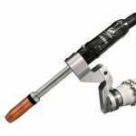
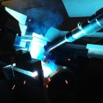
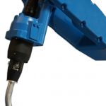
In recent years, the industry has seen advancements in robotic welding technologies that help companies improve productivity and quality and gain a competitive edge. The transition from conventional robots to through-arm robots is among those advancements. These robots require the use of through-arm robotic MIG guns. As the name suggests, the cable assembly of a through-arm MIG gun runs through the arm of the robot, improving its overall durability. The through-arm design naturally protects the power cable and makes it less prone to snag on fixturing, rub against the robot or wear out from routine torsion — all of which can lead to premature cable failure. Since through-arm robotic MIG guns don’t require a mounting arm like conventional robotic MIG guns do, they provide a smaller work envelope. This makes them particularly advantageous when working in tight spaces. Here are the top 10 things to consider when selecting, installing and maintaining a through-arm robotic MIG gun: When choosing a through-arm robotic MIG gun, look for one that offers good power cable rotation. For example, some manufacturers place a rotating power connection on the front of the cable that allows it to rotate 360 degrees. This ability provides stress relief for the cable and power pin, and allows for greater maneuverability for a wider range of applications. It also helps prevent cable kinking that could lead to poor wire feeding, conductivity issues, or premature wear or failure. Choosing a through-arm robotic MIG gun is similar to choosing a conventional robotic MIG gun, except that through-arm guns are sold with predetermined cable lengths. It is still important, however, to choose a gun with power cables that are constructed of durable components and materials to help prevent wear or failure. Always know your robot make and model when placing an order for a new gun to ensure you make the proper selection. Always select the proper amperage of gun and be certain it has the appropriate duty cycle for the given application. Duty cycle is the amount of arc-on time within a 10-minute period; a gun with a 60 percent duty cycle, for example, can weld for six minutes within that period without overheating. As a rule, most manufacturers offer guns up to 500 amps, in both air- and water-cooled models. Check if the robot that the through-arm gun is installed on has collision detection software. If not, identify a clutch that will pair with the gun to help ensure the robot remains safe if it collides with a workpiece or tooling. For through-arm robotic MIG guns, it is important to note that the power cable needs to be installed in a slightly different manner than a conventional over-the-arm robotic MIG gun. Installing a through-arm robotic MIG gun incorrectly can lead to a host of problems, not the least of which is cable failure. Incorrect installation can also cause weld quality issues, such as porosity, due to poor electrical connections; premature consumable failure caused by poor conductivity and/or burnbacks; and, potentially, failure of the entire robotic MIG gun. To prevent such problems, it is imperative to consult the manufacturer’s instructions for each specific MIG gun. When installing a through-arm robotic MIG gun, first position the robot with the wrist and top axis at 180 degrees, parallel to each other. Install the insulating disc and spacer the same as with a conventional over-the-arm robotic MIG gun. Be certain that the power cable position is also correct. The cable should have the proper “lie” with the robot’s top axis at 180 degrees. In addition, it’s important to avoid a very taut power cable, as it can cause undue stress on the power pin. It can also cause damage to the cable once the welding current passes through it. For that reason, it’s important to make sure the power cable has approximately 1.5 inches of slack when installing it. (See Figure 1.) The stud on the front of the power cable needs to be fully inserted into the front connector of the through-arm robotic MIG gun. To achieve this result, always install the stud into the front housing prior to bolting the front end onto the robot wrist. By pulling the cable through the wrist and making the connections in front of the gun, it’s easy to slide the whole assembly back (once the cable is fastened) and bolt it onto the wrist. This extra step will ensure the cable is seated and will allow for maximum continuity and maximum power cable life. Be certain to position the wire feeder in close enough proximity to the robot that the power cable on the through-arm robotic MIG gun will not be stretched unnecessarily after installation. Having a wire feeder that is too far away for the length of the power cable can cause undue stress on the cable and front-end components. Consistent preventive maintenance is key to the longevity of any robotic MIG gun, including the through-arm style. During routine pauses in production, check for clean, secure connections between the MIG gun neck, the diffuser or retaining heads, and the contact tip. Also, check that the nozzle is secure and any seals around it are in good condition. Having tight connections from the neck through the contact tip helps ensure a solid electrical flow throughout the gun and minimizes heat buildup that could cause premature failure, poor arc stability, quality issues and/or rework. In addition, regularly check that the welding cable leads are secured properly and assess the condition of the welding cable on the robotic MIG gun, looking for signs of wear, including small cracks or tears, and replace as necessary. Spatter buildup can cause excessive heat in the consumables and MIG guns, and block shielding gas flow. Visually inspect consumables and the through-arm robotic MIG gun on a regular basis for signs of spatter. Clean the gun as needed and replace consumables as necessary. Adding a nozzle cleaning station (also called a reamer or spatter cleaner) to the weld cell can also help. Like its name implies, a nozzle cleaning station removes spatter (and other debris) that builds up in the nozzle and diffuser. Using this equipment in conjunction with a sprayer that applies an anti-spatter compound can further protect against spatter accumulation on the consumables and the through-arm robotic MIG gun.
Companies invest in robotic welding systems to improve productivity, gain more consistent weld quality and reduce costs. Robotic welding can also set companies apart from the competition by allowing for faster completion and delivery of products. Because of the cost for investing in this equipment, it is important to take steps to protect the system and ensure it is operating at its maximum potential. Keep in mind these best practices and troubleshooting tips to help you avoid downtime and increase throughput in your operation.
Planned downtime for preventive maintenance in the welding operation is not time wasted. Rather, it is a crucial part of keeping production flowing smoothly and avoiding unplanned downtime. Proper maintenance can extend the life of consumables and equipment, and help prevent issues such as birdnesting or burnback that can lead to costly and time-consuming troubleshooting and rework. Keep in mind a few simple maintenance tips and best practices to get the most from your MIG gun and consumables. Prior to welding, ensure all connections are tight and that consumables and equipment are in good condition and free from damage. Start with the front of the gun and work your way back to the feeder. A tight neck connection is essential to carry the electrical current from the welding cable to the front-end consumables. Loose connections at either end of the neck can cause poor electrical conductivity, leading to weld defects and, potentially, overheating of the gun. When using a rotatable neck — one that allows the gun neck to be rotated to the desired position for welding, for increased flexibility and operator comfort — make sure the hand nut on the neck is tight and that the neck is secure in the cable fitting. Also, be sure to visually inspect the handle and trigger to check there are no missing screws or damage. The cable should be free of cuts, kinks and damage along the outer cover. Cuts in the cable can expose the internal copper wiring and create a potential safety hazard to the welding operator. In addition, these issues can lead to electrical resistance that causes heat buildup — and ultimately cable failure. In checking the feeder connection, make sure the power pin is fully inserted and tightly connected, otherwise it can cause birdnesting of the wire at the feeder. A loose connection can also cause electrical resistance at the joint, which could lead to an overheated gun. A clean liner that is the correct size is important in producing quality welds. The liner is often both the most difficult part of the gun to inspect and maintain, and one of the most frequent sources of weld troubles. A liner that is cut too short can cause wire feeding problems. Follow the manufacturer’s instructions for proper trimming and installation of the wire for the best results. Also, take care to keep the liner off the floor during installation to avoid picking up dirt and debris that could enter the weld pool and cause defects. A dirty liner reduces shielding gas flow, which can lead to porosity in the weld. Fragments of welding wire can also chip off and accumulate in the liner. Over time, this buildup can cause poor wire feeding, birdnesting and burnback. To maintain your liner, periodically blow clean compressed air through it to clear out dirt and debris. This task can be done in a few extra minutes during wire changeovers or when removing the wire from the gun — and helps save considerable time in troubleshooting problems later. MIG gun front-end consumables are exposed to heat and spatter and therefore often require frequent replacement. However, performing some simple maintenance can help extend consumable life and improve gun performance and weld quality. The gas diffuser provides gas flow to the weld pool and also connects to the neck and carries the electrical current to the contact tip. Make sure all connections are tight, and check the diffuser’s O-rings for cracks, cuts or damage. The nozzle’s main role is to focus the shielding gas around the weld pool. Watch for spatter buildup in the nozzle, which can obstruct gas flow and lead to problems due to inadequate shielding coverage. Use welper pliers to clean spatter from the nozzle. The contact tip is the last point of contact between the welding equipment and the welding wire. Keyholing of the contact tip is a concern to watch for with this consumable. This occurs when the wire passing through the tip wears an oblong-shaped slot into the diameter of the tip. Keyholing can put the wire out of center and cause problems such as an erratic arc. If you are experiencing wire feeding issues, try changing the contact tip or switching to a larger-size contact tip. Tips that look worn should be replaced. Taking the time for preventive maintenance can pay off in less downtime in the long run. Along with that, always remember to properly store your MIG gun consumables to help you achieve the best results and extend the life of your equipment. When not in use, the gun should be stored in a coiled position, either hanging or lying flat, such as on a shelf. Do not leave MIG guns on the floor of the shop, where there is a chance the cable could be run over, kinked or damaged. Ultimately, the better care you take care of this piece of equipment, the better results you can achieve in the weld cell.
MIG welding is considered among the easiest welding processes to learn and is useful for a variety of applications and industries. Since the welding wire constantly feeds through the MIG gun during the process, it doesn’t require frequent stopping, as with stick welding. The result is faster travel speeds and greater productivity. The versatility and speed of MIG welding also make it a good option for all-position welding on various metals, including mild and stainless steels, in a range of thicknesses. In addition, it produces a cleaner weld that requires less cleanup than stick or flux-cored welding. To maximize the benefits this process offers, however, it is imperative to select the right MIG gun for the job. In fact, this equipment’s specifications can significantly impact productivity, downtime, weld quality and operating costs — as well as welding operators’ comfort. Here is a look at different types of MIG guns and some key factors to consider when making the selection. It is important to select a MIG gun that offers adequate amperage and duty cycle for the job in order to prevent overheating. Duty cycle refers to the number of minutes in a 10-minute period that a gun can be operated at its full capacity without overheating. For example, a 60 percent duty cycle means six minutes of arc-on time in a 10-minute span. Because most welding operators don’t weld 100 percent of the time, it is often possible to use a lower amperage gun for a welding procedure that calls for a higher-amperage one; lower-amperage guns tend to be smaller and easier to maneuver, so they are more comfortable for the welding operator. When evaluating a gun’s amperage, it is important to consider the shielding gas that will be used. Most guns in the industry are tested and rated for duty cycle according to their performance with 100 percent CO2; this shielding gas tends to keep the gun cooler during operation. Conversely, a mixed-gas combination, such as 75 percent argon and 25 percent CO2, makes the arc hotter and therefore causes the gun to run hotter, which ultimately reduces duty cycle. For example, if a gun is rated at 100 percent duty cycle (based on the industry-standard testing with 100 percent CO2), its rating with mixed gases will be lower. It is important to pay attention to the duty cycle and shielding gas combination — if a gun is rated at only 60 percent duty cycle with CO2, the use of mixed gases will cause the gun to operate hotter and become less durable. Deciding between a water- or air-cooled MIG gun depends largely on the application and amperage requirements, welding operator’s preference and cost considerations. Applications that involve welding sheet metal for only a few minutes every hour have little need for the benefits of a water-cooled system. On the other hand, shops with stationary equipment that repeatedly weld at 600 amps will likely need a water-cooled MIG gun to handle the heat the applications generate. A water-cooled MIG welding system pumps cooling solution from a radiator unit, usually integrated inside or near the power source, through hoses inside the cable bundle, and into the gun handle and neck. The coolant then returns to the radiator, where a baffling system releases the heat absorbed by the coolant. The ambient air and shielding gas further disperse the heat from the welding arc. Conversely, an air-cooled system relies solely on the ambient air and shielding gas to dissipate the heat that builds up along the length of the welding circuit. These systems, which range from 150 to 600 amps, use much thicker copper cabling than water-cooled systems. By comparison, water-cooled guns range from 300 to 600 amps. Each system has its advantages and disadvantages. Water-cooled guns are more expensive upfront, and can require more maintenance and operational costs. However, water-cooled guns can be much lighter and more flexible than air-cooled guns, so they can provide productivity advantages by reducing operator fatigue. But because water-cooled guns require more equipment, they can also be impractical for applications that require portability. While a lower-amperage gun can be appropriate for some applications, be sure it offers the necessary welding capacity for the job. A light-duty MIG gun is often the best choice for applications that require short arc-on times, such as tacking parts or welding sheet metal. Light-duty guns typically provide 100 to 300 amps of capacity, and they tend to be smaller and weigh less than heavier-duty guns. Most light-duty MIG guns have small, compact handles as well, making them more comfortable for the welding operator. Light-duty MIG guns offer standard features at a lower price. They use light- or standard-duty consumables (nozzles, contact tips and retaining heads), which have less mass and are less expensive than their heavy-duty counterparts. The strain relief on light-duty guns is usually composed of a flexible rubber component and, in some cases, may be absent. As a result, care should be taken to prevent kinking that may impair wire feeding and gas flow. Also note, overworking a light-duty MIG gun can lead to premature failure, so this type of gun may not be appropriate for a facility that has multiple applications with various amperage needs. At the other end of the spectrum, heavy-duty MIG guns are the best choice for jobs that require long arc-on times or multiple passes on thick sections of material, including many applications found in heavy equipment manufacturing and other demanding welding jobs. These guns generally range from 400 to 600 amps and are available in air- and water-cooled models. They often have larger handles to accommodate the larger cables that are required to deliver these higher amperages. The guns frequently use heavy-duty front-end consumables that are capable of withstanding high amperages and longer arc-on times. The necks are often longer as well, to put more distance between the welding operator and the high heat output from the arc. For some applications and welding operations, a fume extraction gun may be the best option. Industry standards from the Occupational Safety and Health Administration(OSHA) and other safety regulatory bodies that dictate allowable exposure limits of welding fumes and other particulates (including hexavalent chromium) have led many companies to make the investment. Similarly, companies that seek to optimize welding operator safety and attract new skilled welding operators to the field may want to consider these guns, as they can help create a more appealing work environment. Fume extraction guns are available in amperages typically ranging from 300 to 600 amps, as well as various cable styles and handle designs. As with all welding equipment, they have their advantages and limitations, best applications, maintenance requirements and more. One distinct advantage to fume extraction guns is that they remove the fumes at the source, minimizing the amount that enters the welding operator’s immediate breathing zone. Fume extraction guns can, in combination with many other variables in the welding operation — welding wire selection, specific transfer methods and welding processes, welding operator behavior and base material selection — help companies maintain compliance with safety regulations and create a cleaner, more comfortable welding environment. These guns operate by capturing the fumes generated by the welding process right at the source, over and around the weld pool. Various manufacturers have proprietary means of constructing guns to conduct this action but, at a basic level, they all operate similarly: by mass flow or the movement of material. This movement occurs by way of a vacuum chamber that suctions the fumes through the handle of the gun and into the gun’s hose through to a port on the filtration system (sometimes informally referred to as a vacuum box). Fume extraction guns are well-suited for applications that use solid, flux-cored or metal cored welding wire as well as those conducted in confined spaces. These include, but are not limited to, applications in the shipbuilding and heavy equipment manufacturing industries, as well as general manufacturing and fabrication. They are also ideal for welding on mild and carbon steel applications, and on stainless steel applications, as this material generates greater levels of hexavalent chromium. In addition, the guns work well on high amperage and high deposition rate applications. When it comes to cable selection, choosing the smallest, shortest and lightest cable capable of handling the amperage can offer greater flexibility, making it easier to maneuver the MIG gun and minimize clutter in the workspace. Manufacturers offer industrial cables ranging from 8 to 25 feet long. The longer the cable, the more chance it can get coiled around things in the weld cell or looped on the floor and possibly disrupt wire feeding. However, sometimes a longer cable is necessary if the part being welded is very large or if welding operators must move around corners or over fixtures to finish the task at hand. In these cases, where operators are moving back and forth between long and short distances, a steel mono coil cable might be the better choice. This type of cable doesn’t kink as easily as standard industrial cables and can provide smoother wire feeding. A MIG gun’s handle and neck design can impact how long an operator can weld without experiencing fatigue. Handle options include straight or curved, both of which come in vented styles; the choice often boils down to welding operator preference. A straight handle is the best choice for operators who prefer a trigger on top, since curved handles for the most part do not offer this option. With a straight handle, the operator can rotate the neck to place the trigger on top or on bottom. In the end, minimizing fatigue, reducing repetitive motion and decreasing overall physical stress are key factors that contribute to a safer, more comfortable and more productive environment. Choosing a MIG gun that offers the best comfort and operates at the coolest temperature allowed by the application can help improve arc-on time and productivity — and, ultimately, increase the profitability of the welding operation.
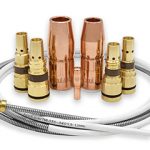
Although MIG gun consumables may seem like small part in the welding process, they can have a big impact. In fact, how well a welding operator selects and maintains these consumables can determine how productive and effective the welding operation is — and how long the consumables last. Below are a few best practices that every welding operator should know when it comes to choosing and maintaining nozzles, contact tips, retaining heads and gas diffusers, and cable. Because nozzles direct the shielding gas to the weld pool to protect it from atmospheric contamination, it is critical that gas flow is unobstructed. Nozzles should be cleaned as often as possible — at least every other welding cycle in a robotic welding operation — to prevent spatter buildup can lead to poor gas shielding or cause short-circuiting between the contact tip and nozzle. Always ream nozzles and remove all spatter with the proper designed cutting blade to prevent damage to the nozzle and to avoid permanently altering it. Even when using a reamer or nozzle cleaning station, periodically inspect the nozzle for spatter adhesion, blocked gas ports and carburized contact surfaces before and after each use. Doing so is added protection to prevent poor gas flow that could affect weld quality. Often, if spatter adheres to a nozzle, it means that nozzle’s life is over. Consider using a quick spray of anti-spatter solution at least every other reaming session. When using this liquid in conjunction with a reamer, be careful that the sprayer never sprays the insert, because the solution will deteriorate the ceramic compound or fiberglass inside the nozzle. For high-temperature robotic welding applications, heavy-duty consumables are recommended. Keep in mind that, while brass nozzles often collect less spatter, they are also less heat resistant than copper. However, spatter more readily adheres to copper nozzles. Choose your nozzle compound according to the application — decide whether it’s more efficient to frequently change over bronze nozzles that burn out faster or consistently ream copper nozzles that last longer but collect more spatter. Typically a contact tip wears out in one area or on one side first, depending on the welding cycle and how tight the| wire is. Using contact tips that can be rotated within the gas diffuser (or retaining head) can help extend the life of this consumable —and possibly even double its service life. Always inspect contact tips and gas diffusers before and after each use to ensure all of the connections are in place and snug. When using an anti-spatter liquid, periodically check gas ports in the gas diffuser for blockage, and regularly inspect and replace the O-rings and metal retaining rings that hold the nozzle in place. Old rings can cause nozzles to fall down or shift positions at the point of connection to the gas diffuser. Next, be sure all of the parts match. For example, when using a coarse threaded contact tip, make sure it is paired with a threaded diffuser that matches. If the robotic welding operation calls for a heavy-duty retaining head, be sure to pair it with heavy-duty contact tips. Lastly, always select the proper diameter contact tip for the wire being used. Note, that some mild steel or stainless steel wire might call for a contact tip with a smaller inside diameter as compared to the wire size. Never hesitate to consult tech support or a sales person to determine which contact tip and gas diffuser combination will best suit the application. Always check the torques of the body tube and end fittings regularly, as loose fitting cables can cause overheating and lead the robotic MIG gun to prematurely fail. Likewise, periodically check all cables and ground connections. Avoid rough surfaces and sharp edges that can cause tears and nicks in the cable jacket; these can also cause the gun to prematurely fail. Never bend cables more than suggested by the manufacturer. In fact, sharp bends and loops in the cable should always be avoided. Often the best solution is to suspend the wire feeder from a boom or trolley, thereby eliminating a large number of bends and keeping the cable clear of hot weldments or other hazards that could lead to cuts or bends. Also, never immerse the liner in cleaning solvents because it will corrode the cable and outer jacket, reducing the life expectancy of both. But do periodically blow it out with compressed air. Finally use anti-seize on all threaded connections to ensure electricity transmission flows smoothly and everything all connections remain tight. Remember, by selecting complementary consumable components and taking good care of them, it is not only possible maximize the efficiency and productivity of the robotic welding operation, but also it is possible to reduce downtime and increase profits. In many cases, MIG gun consumables may be an afterthought in the welding process, as concerns with equipment, workflow, part design and more dominate the attention of welding operators, supervisors and others involved in the operation. Yet, these components — particularly contact tips — can have a significant impact on welding performance. In a MIG welding process, the contact tip is responsible for transferring the welding current to the wire as it passes through the bore, creating the arc. Optimally, the wire should feed through with minimal resistance while still maintaining electrical contact. The position of the contact tip within the nozzle, referred to as the contact tip recess, is just as important. It can influence quality, productivity and costs in the welding operation. It can also affect the amount of time spent performing non-value-added activities, such as grinding or blasting parts that do not contribute to the operation’s overall throughput or profitability. Contact tip recess affects a number of factors that in turn can influence weld quality. For example, stickout or electrode extension (the length of the wire between the end of the contact tip and the work surface) varies according to contact tip recess — specifically, the greater the contact tip recess, the longer the wire stickout. As the wire stickout increases, voltage increases and amperage decreases. When this occurs, the arc may destabilize, causing excessive spatter, arc wander, poor heat control on thin metals and slower travel speeds. Contact tip recess also affects radiant heat from the welding arc. Heat buildup leads to an increase in electrical resistance in the front-end consumables, which reduces the contact tip’s ability to pass the current along to the wire. This poor conductivity can cause insufficient penetration, spatter and other problems that could result in an unacceptable weld or lead to rework. Also, too much heat generally reduces the working life of the contact tip. The result is higher overall consumable costs and greater downtime for contact tip changeover. Because labor is almost always the greatest cost in a welding operation, that downtime can add up to unnecessary increases in production costs. Another important factor impacted by contact tip recess is shielding gas coverage. When the contact tip’s recess positions the nozzle farther away from the arc and weld puddle, the welding area is more susceptible to airflow that can disturb or displace shielding gas. Poor shielding gas coverage leads to porosity, spatter and insufficient penetration. For all of these reasons, it’s important to utilize the correct contact recess for the application. Some recommendations follow. The diffuser, the tip and the nozzle are the three primary parts that comprise MIG gun consumables. The diffuser attaches directly to the gun neck and carries current through to the contact tip and directs the gas into the nozzle. The tip connects with the diffuser and transfers the current to the wire as it guides it through the nozzle and to the weld puddle. The nozzle attaches to the diffuser and serves to keep the shielding gas focused on the welding arc and puddle. Each component plays a critical role in overall weld quality. Two types of contact tip recess are available with MIG gun consumables: fixed or adjustable. Because an adjustable contact tip recess can be changed to varying ranges of depth and extensions, they have the advantage of being able to meet the recess demands of different applications and processes. However, they also increase the potential for human error, since welding operators adjust them by maneuvering the position of the nozzle or via a locking mechanism that secures the contact tip at a given recess. To prevent variations, some companies prefer fixed-recess tips as a way to ensure weld uniformity and achieve consistent results from one welding operator to the next. Fixed recess tips are commonplace in automated welding applications where a consistent tip location is critical. Different manufacturers make consumables to accommodate a variety of contact tip recess depths, which typically range from a 1⁄4-inch recess to a 1⁄8-inch extension. The correct contact tip recess varies according to the application. A good rule to consider is under most conditions, as the current increases, the recess should also increase. Also because less wire stickout typically results in a more stable arc and better low-voltage penetration, the best wire stickout length is generally the shortest one allowable for the application. Here are some guidelines, below. Also, see Figure 1 for additional notes. These considerations can help with the choice, but always consult the manufacturer’s recommendations to determine the right contact tip recess for the job. Remember, the correct position can reduce the opportunity for excessive spatter, porosity, insufficient penetration, burn-through or warping on thinner materials, and more. Moreover, when a company recognizes contact tip recess as the culprit of such problems, it can help eliminate time-consuming and costly troubleshooting or post-weld activities such as rework. Because contact tips are an important factor in completing quality welds and reducing downtime, it’s important to select a high-quality contact tip. While these products may cost slightly more than lesser-grade products, they offer long-term value by extending life spans and reducing downtime for changeover. In addition, higher-quality contact tips may be made from improved copper alloys and are typically machined to tighter mechanical tolerances, creating a better thermal and electrical connection to minimize heat buildup and electrical resistance. Higher-quality consumables typically feature a smoother center bore, resulting in less friction as the wire feeds through. That means consistent wire feeding with less drag, and fewer potential quality issues. Higher-quality contact tips can also help minimize burnbacks and help prevent an erratic arc caused by inconsistent electrical conductivity. Select from Bernard consumables systems
Welding automation offers numerous benefits for companies of all sizes — from improved productivity and weld consistency to lower costs for production, labor and materials.When implemented correctly, robotic welding systems also help companies gain a competitive advantage over those that have not made the transition to this technology. More than ever, smaller shops are beginning to make the investment in automation and realizing positive results. There are, however, various considerations to make before adding a robotic welding system to the shop floor. Selecting the right system, assessing the available facility space and training welding operators properly are just a few factors that can help companies gain the best efficiencies and the best payback. Robotic welding systems offer consistency and repeatability that can lead to significant improvements in productivity and finished part quality. That better quality also helps reduce the time and money spent on rework. In addition, these systems can lower production costs by reducing waste and labor requirements. For example, a robot has the ability to lay down the same amount of weld metal each pass with limited supervision, eliminating the issue of over-welding and the associated filler metal waste and cost. Such benefits translate to many applications in both large and small shops. Yet the investment in even one robotic cell in a smaller shop may result in welding automation taking over a higher percentage of the total welding output, for a potentially greater return on investment (ROI). Likewise, while larger companies may have more resources to draw on when adding welding automation, smaller shops can potentially gain greater flexibility while adding automation. In some cases, the owner may frequently be on the shop floor, and employees may wear multiple hats. The outcome is a collaboration that can result in greater employee buy-in on the purchase and an innovative approach to gaining the best efficiencies. Still, a good rule of thumb for any shop considering robotic welding — small ones included — is to fully evaluate the welding operation and parts before making the purchase. When considering welding automation, shops should ask the question “What are our pains?” By identifying goals before starting the process, the company can determine if welding automation is indeed the right solution. Those goals may include improved throughput, increased welding quality or simplified training for welding operators. Once a company identifies the challenges and goals, considering the following can help: Knowing the benefits robotic welding can provide in a specific shop can offer a better understanding of what the ROI expectations are. ROI estimates should consider the labor rate of each shop and how much time welding automation might save, as well as the ratio of machine uptime to downtime for part and fixture changeover. Some shops may have a single part with enough volume to justify a robotic system. In other shops, it may be necessary to combine multiple parts to get the needed volume for ROI purposes. In those cases, grouping by family of parts (like parts of different sizes, for example), can help improve efficiency and save on downtime for fixture changeover. The robotic welding solution needed for a specific company may require a weld cell that is larger than the area available. The need to expand or modify the space to accommodate a welding automation solution adds to the costs and can greatly impact ROI, so it’s an important consideration to keep in mind. While parts don’t need to be perfect, they do need to be repeatable. If there is a gap in a part, it needs to be a repeatable gap so that it can be welded by the system the same way each time. When there is too much variability in the parts, it can lead to more downtime for adjustment or rework. The workflow for robotic welding will likely be quite different than the workflow for semi-automatic orders, which can be changed more easily and produced in smaller batches. A robotic system typically produces three to five times the number of parts in the same amount of time and requires the throughput to be more consistent throughout the entire process. This is one of the most important factors to operate a successful robotic welding operation — especially for first-time users and smaller shops where technicians may not be in-house. Unfortunately, it is also often one of the most overlooked factors. The initial training on a robotic welding system is critical, and many welding manufacturers offer on-site training to help with installation, basic programming and user training. This training can help prevent common issues that keep the system from functioning properly, such as incorrect liner and/or gun installation. It is also important to conduct ongoing training. The features and functions of robotic welding cells can change, so it’s important to remain up to date on them to make the most out of the investment. There are technologies and solutions available that make it easier and more feasible for smaller shops to add welding automation. Pre-wired and pre-assembled robotic weld cells are one such example. In fact, some preconfigured systems can be up and running within a matter of hours. Offline programming can also provide benefits for companies. It allows shops to program parts and design fixtures before the welding actually takes place in the weld cell. This feature offers the ability to remove any mistakes before material is cut for fixtures and can reduce machine downtime for setup. The result is greater uptime and throughput that is consistently high. Several options in robotic MIG gun technology and peripherals can also help increase productivity and reduce downtime for consumable changeover, further increasing the ROI for smaller shops. A robotic cleaning station (or reamer), for example, removes spatter from front-end consumables without the welding operator entering the cell. This spatter removal helps consumables last longer and reduces downtime for maintenance. Front-loading liner systems available for some robotic welding guns are also designed to minimize downtime and reduce issues with wire feeding. Proper installation of the liner is critical to its ability to guide the wire through the power cable and up to the contact tip. Improper liner installation, which includes trimming the liner too short or having a liner that is too long, can lead to a number of issues, including birdnesting, poor wire feeding and debris in the liner. Front-loading liner technology can save significant time in changeover, by allowing operators to easily change the liner at the front of the gun without removing the gun from the robotic system. Some front-loading liners also have a spring-loaded module to accommodate for up to 1 inch of forgiveness for improperly trimmed liners. Increasingly, the positive impact of welding automation is helping smaller shops become more competitive. To gain the benefit of improved quality and productivity, and to reduce costs, companies should always plan out their robot purchase and implementation carefully. A trusted equipment manufacturer is a good resource to help.
As with any piece of equipment in the shop or on the jobsite, proper storage and care of MIG guns and welding consumables are important. These may seem like rather insignificant components at first, but they can have a big impact on productivity, costs, weld quality and even safety. MIG guns and consumables (e.g. contact tips, nozzles, liners and gas diffusers) that are not properly stored or maintained can pick up dirt, debris and oil, which can hinder gas flow during the welding process and lead to contamination of the weld. Proper storage and care is especially important in humid environments or on jobsites near water, such as shipyards, since exposure to moisture can lead to corrosion of welding guns and consumables — particularly the MIG gun liner. Proper storage of MIG guns, cables and consumables not only helps protect the equipment from damage, but it also improves jobsite safety. Leaving MIG guns or consumables lying on the floor or the ground can lead to tripping hazards that can negatively impact worker safety. It also can cause damage to the welding cables, which could be cut or torn by workplace equipment, such as forklifts. The risk of picking up contaminants is greater if the gun is left on the ground, and can lead to poor welding performance and possibly a shorter life span. It is not uncommon for some welding operators to place the whole MIG gun nozzle and neck into a metal tube for storage. However, this practice puts extra force on the nozzle and/or front end of the gun each time the welding operator removes it from the tube. This action can cause broken parts or nicks on the nozzle where spatter can adhere, causing poor shielding gas flow, poor weld quality and downtime for rework. Another common storage mistake is to hang the MIG gun by its trigger. This practice will naturally change the activation point for the way the trigger level engages the switch. Over time, the MIG gun will not start in the same manner because the welding operator will have to pull the trigger progressively harder each time. Ultimately, the trigger will no longer function properly (or at all) and will require replacement. Any of these common, but poor, storage practices can weaken the MIG gun and/or consumables, leading to poor performance that impacts productivity, quality and costs. For proper storage of MIG guns, keep them out of the dirt; avoid hanging them in a way that could cause damage to the cable or trigger; and keep them in a safe, out-of-the-way location. Welding operators should coil the MIG gun and cable into as small of a loop as possible for storage — make sure it’s not dragging or hanging in the path of high traffic areas. Use a gun hanger when possible for storage, and take care that the gun is hanging from near the handle and that the neck is in the air, as opposed to pointing downward. If a gun hanger is not available, coil the cable and place the MIG gun on an elevated tube, so that gun and cable is off the floor and away from debris and dirt. Depending on the environment, welding operators may choose to coil the MIG gun and lay it flat on an elevated surface. When implementing this measure, make sure the neck is at the topmost vertical point after coiling the gun. Also, minimize a MIG gun’s exposure to the atmosphere when it’s not being used for welding. Doing so can help keep this equipment in good working condition for longer. MIG gun consumables benefit from proper storage and handling, as well. A few best practices can help to achieve a high-quality weld and maintain productivity. Storing consumables, unwrapped, in a bin — especially nozzles — can lead to scratching that can negatively impact performance and cause spatter to adhere more readily. Keep these and other consumables, such as liners and contact tips, in their original, sealed packaging until they are ready for use. Doing so helps protect the consumables from moisture, dirt and other debris that can damage them and minimizes the opportunity to cause poor weld quality. The longer consumables are protected from the atmosphere, the better they will perform — contact tips and nozzles that are not stored properly can wear before they are even used. Always wear gloves when handling consumables. Oil and dirt from the welding operator’s hands can contaminate them and lead to problems in the weld. When installing MIG gun liners, avoid uncoiling the liner and letting it drag on the floor when feeding it through the gun. When that happens, any contaminants on the floor will push through the MIG gun and have the potential to impede gas flow, shielding gas coverage and wire feeding — all factors that can lead to quality issues, downtime and potentially, cost for rework. Instead, use both hands: Hold the gun in one hand and uncoil the liner naturally with the other hand while feeding it through the gun. Proper storage of MIG guns and consumables can seem like a small issue, especially in a large shop or jobsite. However, it can have a great effect on costs, productivity and weld quality. Damaged equipment and consumables can lead to shorter product life, rework of welds and increased downtime for maintenance and replacement.
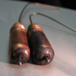
While only one part of a much larger system, the contact tip in both robotic and semi-automatic welding MIG guns plays a critical role in providing sound weld quality. It can also factor measurably into the productivity and profitability of a welding operation — downtime for excessive changeover can be detrimental to throughput, and the cost for labor and inventory. The major functions of a contact tip are to guide the welding wire and transfer the welding current to the wire as it passes through the bore. The goal is to have the wire feed through the contact tip smoothly, while maintaining maximum contact. To get the best results, it is important to have the right contact tip size —or inner diameter (ID) — for the application. The welding wire and welding process both influence the selection.
There are many considerations that factor into a company’s ability to achieve the best quality and highest productivity in the welding operation. Everything from selecting the right power source and welding process to the organization of the weld cell and workflow play a role in that success. Although a smaller part of the whole operation, MIG guns also play an important part. In addition to being responsible for delivering the current to create the arc that generates the weld, MIG guns are also the one piece of equipment that directly impacts the welding operator — day in and day out, shift after shift. The heat of the gun, along with the weight and repetitive motion of welding make it necessary to find the right gun to improve comfort and allow the welding operator the opportunity to put his or her best skills forward. With that in mind, MIG gun manufacturers throughout the industry have identified ways to make MIG guns more ergonomic and perform better. Changes that help expedite welding operator training and improve the welding environment also continue to emerge, as do MIG guns designed to reduce costs. Manufacturers continue to build features into MIG guns to help welding operators gain the highest level of quality, while also assisting them in producing a greater level of throughput. While it may seem like a minor advancement, the addition of a swivel at the base of the MIG gun handle has become an important feature that contributes positively to welding operator comfort and productivity. MIG guns that provide a 360-degree swivel offer greater maneuverability for accessing weld joints and are less fatiguing to adjust throughout the course of a welding shift. This feature also reduces the strain on the power cable, resulting in less downtime and costs for changeover. The addition of rubber handle over-molding, which is becoming more popular in industrial settings, can further improve MIG gun ergonomics by providing welding operators with a more secure and comfortable grip. The over-molding can also help reduce vibrations during the welding process, minimizing hand and wrist fatigue. MIG gun manufacturers are also adding in features to their products that help minimize costs. Among those are front-loading liners. These liners, as their name implies, load from the front of the gun (after the initial installation of the system), as opposed to conventional liners that load from the back of the gun. The benefit to front-loading liners is that they simplify installation. After the initial installation of the front-loading liner system (completed similarly to a conventional liner), the welding operator or maintenance personnel needs only to remove the nozzle and retaining head, pull out the existing front-loading liner and replace it with a new one; the gun remains attached to the feeder during this process, and wire also remains in place. As a rule, front-loading liners can cut installation time in half, minimizing costly downtime. Some manufacturers also offer a spring-loaded module that works in conjunction with a front-load liner to help minimize issues if the liner has accidentally been trimmed to an incorrect length. These modules sit in the power pin and put forward pressure on the liner after installing it from the front of the gun, providing up to 1 inch of forgiveness if the liner is too short. As companies seek out ways to address environmental regulations and create a safer, cleaner and more compliant welding operation, fume extraction guns have increased in popularity. These guns capture weld fume and visible smoke right at the source, over and around the weld pool. They operate by way of a vacuum chamber that suctions the fumes through the handle of the gun, into the gun’s hose through to a port on the filtration system. While effective in helping remove weld fume, fume extraction guns in the past have been rather heavy and bulky; they are larger than standard MIG guns in order to accommodate the vacuum chamber and the extraction hose. This extra bulk could increase welding operator fatigue and limit his or her ability to maneuver around the welding application. Manufacturers today offer fume extraction guns that are smaller (near the size of a standard MIG gun) and that feature swiveled handles to make them easier to manage. Some fume extraction guns now also feature adjustable extraction control regulators at the front of the gun handle. These allow welding operators to easily balance suction with shielding gas flow to protect against porosity. As the fabrication and manufacturing industries evolve, companies need to seek out welding equipment that can meet those changing demands — and no single MIG gun can do the job for every application. To ensure companies have the exact MIG gun necessary, many manufacturers have moved toward configurable products. MIG guns can be custom built, usually using an online configurator, according to multiple options: amperage, cable type and length, handle type (straight or curved), and neck length and angle. These configurators also offer the option to select the type of contact tip and MIG gun liners. Upon selecting the desired features for a given MIG gun, companies can purchase the unique part number through a welding distributor. Adding to the configurability of many of today’s MIG guns are accessories designed to augment their performance. Flexible necks, for example, can save labor and time by allowing the welding operator to rotate or bend the neck to the desired angle. Neck grips can add to operator comfort by reducing heat exposure and helping the welding operator maintain a steady position, leading to less fatigue and better weld quality. With the advent of advanced welding information management systems — software-driven solutions that gather weld data and can monitor most every aspect of the welding process — specialized MIG guns with a built-interface have also been introduced to the marketplace. These guns pair with the weld sequencing functions of the welding information management system, using the screen to guide the welding operator through the order and placement of each weld. Similarly, some welding performance training systems feature MIG guns with built-in displays that provide visual feedback regarding proper gun angle, travel speeds and more, allowing the welding operator to make corrections as he or she trains. Both types of guns have been designed to help streamline welding operator training and, like other MIG guns in today’s marketplace, can help support the creation of high-quality welds and positive levels of productivity in the welding operation. As companies seek out means to increase productivity and improve quality, the investment in welding automation continues to grow across the fabrication and manufacturing industries. Along with providing greater efficiencies, robotic welding systems allow companies to streamline their operations to gain cost savings and to position themselves favorably among the competition. Selecting the right robot and power source, and ensuring that the parts to be welded lend themselves to automation — namely that they are repeatable and offer joint accessibility — are all vital to success. There are also steps that companies can take to optimize the robotic welding process by way of the robotic gas metal arc welding (GMAW) gun. From making the proper selection for the application to implementing appropriate preventive maintenance and more, this component can help support greater arc-on time, reduce costs and help companies realize the benefits of welding automation. Determining the right robotic GMAW gun depends on the application, including the type and thickness of material being welded, the length of the weld and the amperage required. The type of robotic welding system also factors into the decision, as through-arm robots are becoming more prevalent in the industry and replacing many conventional robots due to their ability to reduce cable wear from routine torsion. In this case, a through-arm robotic GMAW gun, in which the cable assembly runs through the arm of the robot (as opposed to over it), is necessary. As with conventional GMAW guns, through-arm style guns are available in air- or water-cooled varieties. In most applications, air-cooled GMAW guns provide the necessary cooling capacity to protect against premature failure and offer good performance. These guns rely on both the copper in the unicable and the ambient air for cooling. In addition to working well on lower amperage applications, for welding materials up to 0.16-inch thick and for short, high-volume welds, air-cooled GMAW guns are also quite sturdy. In heavy equipment manufacturing and similar industries, water-cooled robotic GMAW guns are often chosen due to their ability to weld on thicker materials (over 1/4 inch) for longer periods of time. While more expensive up front and more to maintain, these guns offer high amperages (usually 300 to 600 amps) at 100 percent duty cycle, which makes them well suited for long weldments. These GMAW guns operate by circulating coolant from a radiator unit through the power cable via cooling hoses and through the gun and neck. This coolant returns to the radiator where it releases the heat that it absorbed during the welding process. Because of the water circuit, there is the potential for leaks so companies should take care to implement a preventive maintenance schedule to help protect against issues. In the event that a company welds materials of a variety of thicknesses at low and high amperages, a good choice for a GMAW gun is a hybrid variety featuring a durable air-cooled neck with external water lines. The neck, power cable and other components chosen for a robotic GMAW gun can have a measurable impact on welding performance and productivity. The goal with each of these items is to keep them functioning correctly and prevent premature failure so that the robot can maintain the high levels of arc-on time it was designed to provide. It is important that the robotic GMAW gun is able to access the weld joint accurately and fully, and utilizing the proper neck style and length for the job is key. Typically, GMAW gun manufacturers offer necks in multiple angles ranging from 22 to 180 degrees, and in various lengths to accommodate most robotic welding applications. In some cases, however, it may be necessary to special-order a neck. Whichever the case, having a neck that can reach the weld joint appropriately can reduce weld defects by completing the weld properly the first time, and eliminate downtime for rework. The right power cable style and length on a robotic GMAW can also help companies achieve efficiencies in the robotic welding operation. In a through-arm robotic application, the selection is simpler, as the power cable is typically sold in set lengths to match a specific make and model of robot. Still, companies may want to consider additional options for these components, such as power cables with a rotating connection. This feature helps relieve stress on the cable and power pin, resulting in less kinking and a longer life. For conventional robots, selecting the correct length of power cable is important — too long of a cable can easily kink or whip around during the welding process, whereas too short of a cable can stretch and wear more quickly. Both can result in premature cable failure, and downtime and costs for cable replacement. When in doubt about the selection, contact a trusted robotic integrator, robotic GMAW gun manufacturer or welding distributor for assistance. Companies should also look for sturdy power cables that are able to withstand UV damage from the arc and resist wear, as well as those with quick-change features to further extend cable life, simplify changeover and prevent interruptions to the welding process. Using high-quality consumables — nozzles, contact tips and gas diffusers — is another way to improve the robotic welding operation and protect the robotic GMAW gun. For higher-amperage applications, companies may want to consider a chrome zirconium contact tip to withstand the higher heat levels. The connections between consumables should always be tight to prevent electrical resistance that could lead to failure and to gain good conductivity for a smooth and stable arc. When possible, adding a nozzle cleaning station or reamer to the robotic weld cell can further optimize the performance of the consumables and the robotic GMAW gun by ensuring that the nozzle is free of spatter and able to direct the shielding gas to the weld pool to protect the weld. It can also help minimize the risk of the consumables overheating. In certain instances, companies may reprogram the robot after a collision in order to re-establish tool center point (TCP) with a bent robotic GMAW gun neck. As an alternative, a neck checking fixture (or neck inspection fixture) can adjust the neck back to the correct TCP to help improve the performance of the gun and gain greater arc-on time. The neck checking fixture tests the neck profile to ensure that the contact tip will meet the TCP. If the tool point is off because of an impact or other problem, it readjusts the neck back to the correct position. This peripheral can also be used to inspect a new robotic GMAW gun neck prior to installation to ensure it is accurate. For companies that maintain a large number of robotic welding cells, a neck checking fixture can reduce downtime and costs when exchanging necks from one robotic GMAW gun to another — welding operators need only to remove the damaged or bent neck and replace it with a spare one that has been inspected already to get the robot back to welding immediately. The damaged neck can then be set aside for adjustments while the robot is already online. For newer robots with more sophisticated collision detection software, using a solid mount to protect the gun in the event of an impact can also help maintain a more accurate TCP than a clutch mount. Unlike a clutch mount that is designed to move, these durable, high-strength mounts offer greater repeatability for higher weld quality. They are also less expensive. To help maintain accuracy, quality and speed in the robotic welding operation, additions to the robotic GMAW gun like air blast and wire brake features are beneficial. An option for both air- and water-cooled robotic GMAW guns, the air blast feature forces high-pressure air through the front of the gun to help remove debris that could enter the weld pool and negatively affect weld quality. Welding operators can program the air blast feature to operate between weld cycles to reduce unnecessary downtime. Another option for robotic GMAW guns to help optimize welding performance is the addition of a wire brake feature. As its name implies, a wire brake prevents wire feeding when welding stops. The result is a consistent wire extension at the beginning of every weld, a factor that especially complements robots using touch-sensing software — the wire brake keeps the wire in position as the robot searches for the weld joint location. This optional robotic GMAW gun feature also keeps the wire from unspooling during arc starting and stops. Preventive maintenance (PM) is critical for gaining optimal performance from a robotic GMAW gun, whether it is air- or water-cooled or a conventional or through-arm style. Recommend PM activities include: The frequency of the PM schedule will depend on the size of the robotic welding operation and the application. Companies with large weldments on thick materials stand to have greater costs and downtime for rework should the gun fail and cause a quality issue. Maintaining the robotic GMAW gun more frequently is advised.
Selecting equipment to provide the highest quality and productivity in a welding operation goes beyond just the power source or welding gun — consumables play an important role, as well. Contact tips, in particular, can make a significant difference between running an efficient process and accruing downtime to rectify problems. Selecting the right contact tip for the job can also impact the profitability of the welding operation. Contact tips are responsible for transferring the welding current to the wire as it passes through to create the arc. Optimally, the wire should feed through with minimal resistance, while still maintaining electrical contact. For that reason, it is always important to select a high-quality contact tip. While these products may cost slightly more than lesser-grade products, there is long-term value to negate that upfront purchase price. Namely, higher-quality contact tips are typically machined to tighter mechanical tolerances, creating a better thermal and electrical connection. They may also feature a smoother center bore, resulting in less friction as the wire feeds through. That means consistent wire feeding with less drag, which eliminates potential quality issues. Higher-quality contact tips can also help minimize burnbacks (the formation of a weld inside the contact tip) and help prevent an erratic arc caused by inconsistent electrical conductivity. They also tend to last longer. Contact tips used for semi-automatic MIG welding are typically composed of copper. This material provides good thermal and electrical conductivity to allow consistent current transfer to the wire, while also being durable enough to withstand the heat generated during the welding process. For robotic welding, some companies choose to use heavier-duty chrome zirconium contact tips, as these are harder than copper ones and better withstand the increased arc-on time of an automated application. In most cases, using a contact tip that matches the size of the wire leads to the best results. However, when wire is fed from a drum (e.g. those 500 pounds and larger) and/or when using solid wire, an undersized contact tip may improve welding performance. Because wire from a drum tends to have less cast, it feeds through the contact tip with less or no contact — having a smaller bore exerts more pressure on the wire, creating greater electric conductivity. Undersizing a contact tip, however, can increase friction, resulting in erratic wire feeding and, potentially, burnback. Conversely, using an oversized tip can decrease current transfer and increase tip temperatures, which can also lead to wire burnback. When in doubt about selecting the proper size contact tip, consult a trusted consumable manufacturer or welding distributor. As a best practice, always check the connection between the contact tip and the gas diffuser to be certain it is secure — a secure connection reduces electrical resistance that could lead to overheating. Contact tip recess refers to the position of the contact tip within the nozzle and is an important factor influencing weld quality, productivity and costs in a welding operation. Specifically, correct contact tip recess can reduce the opportunity for excessive spatter, porosity and burnthrough or warping on thinner materials. It can also help minimize radiant heat that could cause premature contact tip failure. Contact tip recess directly impacts wire stickout, also called electrode extension. The greater the recess, the longer the stickout is and the higher the voltage, which can make the arc slightly less stable. For that reason, the best wire stickout is generally the shortest one allowable for the application; it provides a more stable arc and better low-voltage penetration. Typical contact tip positions are 1/4-inch recess, 1/8-inch recess, flush and 1/8-inch extension. Refer to Figure 1 for recommended applications for each. Contact tip failure can result from a number of influences, including burnbacks, mechanical and electrical wear, poor welding operator technique (e.g., variations in gun angle and contact-tip-to-work-distance [CTWD]) and reflective heat from the base material, which is common in tighter access weld joints or confined areas. The quality of the wire being used can also affect contact tip life. Poor quality wire often has an undesirable cast or helix that can cause it to feed erratically. That can prevent the wire and contact tip from connecting properly through the bore, resulting in low conductivity and high electrical resistance. These issues can lead to premature contact tip failure due to overheating, as well as poor arc quality. To extend contact tip life, consider the following: In some instances, it may be desirable to convert to a water-cooled MIG gun to help keep the front-end consumables, including the contact tip, cooler and running for longer. Companies should also consider tracking their contact tip usage, noting excessive changeover and addressing accordingly with some of the suggested precautions. Addressing this downtime sooner than later can go far in helping companies reduce unnecessary costs for inventory, while also improving quality and productivity.
For some fabricators, the choice between an air-cooled or a water-cooled robotic MIG welding gun is simple. Some heavy-duty applications simply demand a water-cooled model due to the high amperage and duty cycle requirements of the job — performance requirements that would cause an air-cooled gun to quickly overheat and fail. However, there are other less conventional robotic welding applications that may benefit from using a water-cooled MIG gun, too, and can contribute to much lower consumable costs and greater productivity. Water-cooled MIG guns typically have higher duty cycles and amperages, meaning they can be run for longer periods of time without stopping. Cooler guns mean cooler front-end consumables. In particular, it is possible to greatly extend contact tip life with these guns compared to air-cooled models. Deciding which system is the best choice involves careful analysis of several factors. In addition to amperage requirements and duty cycle, a fabricator should consider the up-front costs, potential return on investment (ROI) and the application specifics. Some fabricators may choose water-cooled robotic MIG guns based on the length of welds — the long arc-on time needed to produce these welds generates more heat in the gun. Similarly, critical start and stop points along a longer weld joint typically require a gun that can handle the extended amount of welding. Considering the weld joint design and the material type and thickness, as well as joint access can also factor into whether to choose a water-cooled MIG gun. For example, aluminum or heavy plate sections that have been pre-heated can generate substantial radiant heat that affects the cooling of the gun and can adversely affect the life of the front-end consumables. A water-cooled gun can help here. Some water-cooled robotic MIG guns have smaller diameter necks than air-cooled model due to optimized cooling capacity that requires less copper in the neck. As a result, they can reach into tighter spaces, through complex tooling restraints or into parts with access holes. When deciding whether a water-cooled robotic MIG gun is the best choice, it’s important to keep in mind that these products require more maintenance and often have a higher up-front cost. It is necessary to weigh those factors against the productivity gains and savings that can result from longer consumable life. Keeping MIG welding equipment cool is necessary to protect the power cable, gun body, neck and consumables from damage due to the radiant heat from the arc and the resistive heat from the electrical components in the welding circuit. A traditional water-cooled robotic MIG gun circulates a coolant from a radiator unit through cooling hoses inside the power cable and into the gun body and neck. The coolant returns to the radiator where the radiator’s baffling system releases the heat absorbed by the coolant. There are guns available on the market today, however, that cool only the front of the gun where heat is generated and still use an air-cooled cable. These features help save costs and eliminate potential leaks from the cable bundle where excess movements from whipping and repetitive motion create the greatest wear. These features contrast to a completely air-cooled MIG welding system, which relies solely on the ambient air and shielding gas to dissipate heat that builds up along the length of the welding circuit. Air-cooled systems use much thicker copper cables, and inner neck tubes; water-cooled robotic MIG guns use much less copper in the power cables and thinner wall sections in the necks because the cooling solution carries away the resistive heat before it builds up. In general, water-cooled robotic MIG guns are beneficial for high-amperage applications and are typically available in 300 to 600 amp models. Closely related to amperage is duty cycle, which refers to the amount of time during a 10-minute cycle that the gun can operate at its rated capacity without overheating. Water-cooled robotic MIG guns can have varying duty cycle capacity depending on the manufacturer and model. The amperage requirements, the length of time the arc is actually operating, and how the system will deal with the heat of welding in a specific application are among the most important considerations when choosing a water-cooled robotic MIG gun. When choosing a water-cooled robotic MIG gun, be sure to select a product and consumables that use high quality materials that can handle high heat. Guns on the market come in two styles: conventional and through-arm versions.Through-arm robotic MIG guns carry the cable assembly through the arm of the robot. This style can offer greater protection since the arm of the robot shields the power cable from abrasive wear and minimizes cable whipping during air moves. It’s important to know if the robotic arm is a conventional or through-arm style, so the gun and associated mounting bracket can be chosen to match. Knowing the robot model is also important for proper mounting hardware and insulating of the gun from the robot wrist. As with air-cooled applications, make sure during installation that the selected water-cooled robotic MIG gun allows proper joint access. Having a neck design with the proper geometry that accesses the joint with the appropriate travel and work angles can prevent poor weld quality and/or the need to re-tool expensive fixtures, which could add downtime. To make sure the cable bundle is the correct length, it’s also critical to know where the wire feeder will be located on the robot. If a cable bundle is too short, it might stretch; if it’s too long, it could interfere with opposing structures and also fail prematurely due to excess flexing. Some water-cooled robotic MIG guns on the market have features that make them especially easy to use and to integrate into the robotic welding system. One available feature is the quarter-turn connection, which helps establish a quick and tight connection to help maintain good conductivity and prevent shielding gas leaks. Models with the quarter-turn connection feature are designed to seat the connection properly once a quarter turn is made, making it much easier and faster to change the neck. Water-cooled robotic MIG guns with this quarter-turn connection feature also offer an automatic shutoff valve, to shut off the water flow any time the neck is changed, which helps simplify routine maintenance. Consider adding a flow switch to a system with water-cooled robotic MIG gun. These switches ensure water is flowing through the system; if the system doesn’t detect the flow of water in the gun, it will shut down and give an error message. Operating a gun without water flow will very quickly cause a catastrophic failure. All of this means added downtime and costly repairs. Water-cooled robotic MIG guns do require more maintenance than air-cooled models, since the presence of the water circuit introduces more potential issues. For example, if a hose or the neck is leaking, coolant could drip into the molten weld pool, leading to porosity and costly rework. It’s a good idea to conduct preventive maintenance each day or before the start of each shift. Just as with any welding system, it’s important to inspect a water-cooled robotic MIG gun to ensure that all consumables and connections are tight and working properly. Inspect the water lines frequently to make sure they are tight and have no leaks, and replace the O-rings when necessary (e.g., when cracks or wear appears). Using an automatic reamer or nozzle cleaning station adds significant benefits to the preventive maintenance of water-cooled robotic MIG guns. A reamer eliminates the need to manually clean out the front-end consumables and can, with the addition of an automated sprayer, add anti-spatter compound to help extend consumable life further. This feature adds to the overall cost of the equipment, but helps increase uptime for production, with less manual intervention, and offers a solid return on investment in most robotic welding operations. Do not fall prey to the notion that it is cheaper to use tap water in a water-cooled gun, as it can cause algae growth or mineral build-up and eventually clogging. Instead, use deionized water or the specially treated coolant solution recommended by the manufacturer. These coolants contain special additives to lubricate internal pumps and O-rings, as well as to prevent algae growth. Choosing a water-cooled robotic MIG gun is often a necessity because of the demands of the application. A water-cooled model requires more up-front investment and more maintenance, but it can provide significantly longer consumable life and increased productivity from fewer consumable changeovers. Consider the various costs, specific application needs and accessibility to decide if a water-cooled robotic MIG gun offers a good option for a specific robotic application. Often a welding distributor, welding equipment manufacturer or robotic welding system integrator can help. Manufacturing and fabrication environments are dynamic, ever changing with the economy, customer demands, available labor and skill sets, and competitive forces, among other factors. To maintain a favorable position in the industry, it is critical for companies to continually look for ways to increase efficiencies while also improving quality and decreasing costs. For many, that means a shift toward welding automation, which has experienced its own changes in the last 10 years. During this time, robotic welding manufacturers have transitioned away from the manufacture of conventional robotic welding systems to the development of through-arm styles, in which the power cable of the robotic MIG gun runs through the arm of the robot as opposed to over top of it. These are now the prevalent robot styles in the industry and this change has had a direct impact on the design of the robotic MIG guns for the marketplace. But it is not the only trend associated with robotic MIG guns. Like any component of the welding operation, this equipment has continued to evolve to the demands of the industry and to provide solutions to improve the business of welding. Improving and simplifying cable management has been the driving force behind the shift toward through-arm robots and, therefore, the development of through-arm robotic MIG guns to accompany them. With conventional style robots and guns, the cable is prone to “whipping” during air movements, which causes undue stress on this portion of the gun, and can lead to premature wear and failure caused by the cable rubbing against the robot or tooling. It also creates additional cost and time for companies to implement cable management systems. The through-arm style robot and through-arm robotic MIG gun make it easier for companies to minimize downtime associated with cable management and reduce costs for cable replacement. It also eliminates the risk of selecting the wrong cable length, a common mistake that occurs with conventional robotic MIG guns. The through-arm robot model dictates the length of the robotic MIG gun cable, so there is no concern about it being too long (which requires extra cable management or could cause wire feeding issues) or being too short (which can cause the cable to stretch and fail prematurely) — both issues associated with conventional robotic MIG guns. There are other benefits to the shift to through-arm robots and through-arm robotic MIG guns, namely that they can accommodate for increases in welding speed that are also becoming customary in the industry. Robots are getting much faster, but with the through-arm robot there is no longer the concern of the robotic MIG gun cable getting caught on tooling during quick movements. Too, it is easier to complete offline robot programming or welding simulation and have it work with these robots because there is less concern about having to accommodate for clearance for the power cable in an application. If a robotic MIG gun fitted for a through-arm robot works in simulation, it will most likely work in the real-world application. As companies strive for greater arc-on time and higher productivity, robotic MIG gun manufacturers are helping by providing increasingly more durable power cables on this equipment and implementing features that simplify cable changeover. Some manufacturers offer a rotating power connection on the front of the cable that allows the robot to spin on its final axis as much as necessary without binding the cable. This feature helps minimize stress due to routine torsion and to extend the life of this part of the gun, as well as to increase the robot’s operating range by allowing it to rotate a full 720 degrees (360 degrees in both directions) and weld faster. Built-in quick-change features on many robotic MIG guns also expedite cable replacement, adding to the operation’s productivity, while the use of stronger cable materials help better resist wear and UV damage from the arc for longer component life. Another trend associated with robotic MIG guns is the use of solid mounts (also called solid arm mounts) as opposed to the clutch mounts that were used previously to protect the gun in the event of a collision — an occurrence commonly caused by an incorrectly position work piece or tooling that has been left out of position, among other factors. This trend is due to more sophisticated collision detection software being built into today’s robots. This software is increasingly capable of monitoring current rates and/or torque so it can quickly stop the robot when an impact occurs. Solid mounts are made from durable, high-strength aluminum alloys, and are an alternative to the clutches used with older robot models. There are two key benefits to using a solid mount for robotic MIG guns compared to a clutch: Clutches (also called shock sensors) are designed to recognize the physical impact of the robotic MIG gun on a solid surface during a collision and send an electrical signal back to the robot controller, causing the system to stop. While effective, clutches are designed to move, which can affect tool center point (TCP) after a collision. Also, since it is an electrical device, it costs more than a solid mount and is more prone to failure because of its internal components — expenses that many companies can now happily omit. As companies seek ways to become more competitive and produce higher volumes of parts, they need to maximize floor space to make room for more robots to do the job. As a result, robots and welding cells are becoming smaller and in many instances, tooling has become more complex. These changes pose greater space constraints when it comes to the robotic MIG gun. Many robotic MIG gun manufacturers have responded to this trend by creating guns that provide a more open work envelope around the mounting arm (the depth from the wrist of the robot to the tip of the robotic MIG gun) so maneuvering around tooling and gaining joint access becomes less cumbersome. There are also more options for neck lengths and angles available for robotic MIG guns, which helps companies gain access to complicated joints. Because many robotic welding applications tend toward higher amperages and longer arc-on times, it is critical for companies to have a robotic MIG gun that provides adequate amperage without overheating. The complexity and increased cost of water-cooled robotic MIG gun systems (compared to air-cooled models), however, make some companies wary of the investment for their high amperage applications. Too, if there is an issue with the coolant flow, there is the risk of the robotic MIG gun overheating and failing — an event that can be costly not just for replacement of the gun, but also potentially for rework of the part should quality problems occur. A development in recent years that addresses this concern is a hybrid robotic MIG gun. This type of gun has a durable neck like an air-cooled model and water lines that run external to the neck down to the nozzle. Should the coolant flow fail, the gun can rely on the underlying air-cooled unicable to provide enough current-carrying capacity for the job for a period of time, saving downtime and costs to address a complete robotic MIG gun failure. These guns also offer the higher amperage associated with a standard water-cooled gun, making them a good option for companies who need greater cooling capacity for an application. Because time is at a premium when it comes to robotic welding, companies are always looking for ways to extend their robotic welding cycle time — down to the second. To help maintain greater arc-on time while still protecting the robotic MIG gun and consumables from spatter build-up that could affect weld quality, adding air blast to robotic MIG guns is becoming a popular choice with some companies. This optional feature can be added to the robotic MIG gun and functions by blowing compressed air through the gun at a high pressure (approximately 100 pounds per square inch — psi) to clear debris loose in the front end while the robot is moving out of the way so the table/fixture can index. This addition can help companies reduce the number of times that the robotic MIG gun needs to be reamed out by a reamer or nozzle cleaning station, resulting in more arc-on time and greater productivity. While robotic MIG guns may seem like a small part of the whole automated system, their design and functionality can have a significant impact on the cost, productivity and quality of an application. The trends discussed here are just some of the ways that robotic MIG gun manufacturers have adjusted the designs and capacity of the products to help companies gain the best results in recent years. As with any piece of welding equipment, robotic MIG guns will need to continue evolving just like any equipment in order to meet companies’ changing needs and to meet the demands of the fabrication and manufacturing industry.
Consider some of the top things to know about robotic MIG guns as a way to get the most out of this equipment. When it comes to robotic welding, precision, repeatability and speed are essential to ensuring a successful outcome in the operation. In order to gain the best benefits, companies rely on the robot’s ability to execute the same weld, exactly the same way and as fast as possible. And while the robot itself, proper programming and oversight by a trained welding supervisor are all important components in the robotic welding operation, the robotic MIG gun also has a direct impact on quality and productivity, as well as costs.
Equipment repairs are a fact of life on most jobsites, so finding ways to reduce costs and downtime while making them is important for overall efficiency and productivity — and the bottom line. The welding operation on a jobsite, just like any other portion of the business, offers opportunities to conserve resources and extend equipment life. Proper selection, handling and use of welding consumables and accessories can be helpful when it comes to getting the most out of a MIG gun, as can proper gun maintenance. Jobsites are often exposed to many environmental challenges, including extreme hot and cold temperatures, and the presence of rain and mud. It’s important to keep nozzles, gas diffusers and contact tips in the original packaging to protect against these elements until they are ready for use. Doing so also prevents scratches and/or dents from forming where spatter can accumulate and cause the consumables to fail prematurely. In addition, it prevents dirt, oil or other debris from adhering to the consumables and inadvertently entering the weld puddle, which can lead to poor weld quality. Remember, proper storage and handling doesn’t just lower actual costs for consumables by extending consumable life, it can also prevent weld defects that require costly and time-consuming rework. Choose the most appropriate neck for a MIG welding application in order to increase comfort and control, and save money. Rotatable necks, for example, can be adjusted without tools, so neck angles can be quickly changed during a welding repair once the desired position is determined. This feature is important on a jobsite where welding may be done in various positions or in tight spaces, and it helps reduce downtime for changing over MIG guns or for purchasing and inventorying extras. Rotatable necks are especially useful for welding on different angles. For hard-to-reach areas, consider a neck coupler, which allows for two existing necks to connect to extend their reach — again without the cost of purchasing a new or specialized neck. Flex necks are another good option for saving money and gaining greater comfort and control, particularly for applications with tighter joints. The operator can bend the neck to multiple angles to work around corners or get into small spaces for greater flexibility during repairs, without the expense of stocking different neck angles. Regularly perform a visual inspection of the nozzle — inside and outside — to look for spatter build-up. If there is accumulation, either clean the nozzle with a tool designed specifically for the job or replace the nozzle when necessary. During the inspection, also check that the nozzle, contact tip and retaining head are tightened properly, as these components can naturally loosen during welding. Inspecting and tightening consumables help ensure good shielding gas coverage, reliable electrical conductivity and consistent weld quality, as well as reduce costs for purchasing and replacing new consumables. It is also important to inspect the power cable on the MIG gun for any wear or damage, replacing it as necessary to avoid potential problems. Always trim MIG gun liners according to the manufacturer’s recommendations, using the proper tools and cutting the liner to the correct length. Too long of a liner can cause kinking, while cutting it too short allows debris to build up between the liner and the gas diffuser. Either way, the wrong liner length can cause poor wire feeding and premature failure of both the liner and the contact tip, adding unnecessary costs. Use a liner gauge when possible to determine the proper length for the particular liner being used. Also be certain that there are no burrs or sharp edges after the liner is cut. Also, keep the liner away from contaminants (e.g., don’t let it drag on the ground) during installation. As further protection, the welding operator’s hands or gloves should be clean when handling the liner. These precautions protect against contaminants that could enter the weld puddle and cause costly weld quality issues or downtime for rework. Use the shortest length MIG gun cable possible for the welding application, as it minimizes the opportunity for kinking, as well as premature wear of both the cable and the MIG gun liner. A shorter cable also helps prevent wire-feeding problems that could lead to an erratic arc, poor weld quality and unnecessary downtime for rework or consumable replacement. It also tends to cost less, adding to savings for repair jobs. In addition, remember to choose the correct diameter liner and contact tip for the welding wire, as this prevents similar problems and helps extend the life of these consumables. While up-front cost is an important factor when choosing consumables, consider the long-term savings offered by purchasing sturdier and more expensive consumables. These consumables likely will last longer — especially in the face of the harsh conditions of some jobsites — reducing the downtime associated with changeover and the cost of more frequent replacement of the consumables themselves. As an additional defense against spatter accumulation, purchase nozzles that have a smooth, non-porous surface. Be sure to check that the nozzles are free of any sharp edges or flat spots that would further allow spatter to adhere. Whenever possible, purchase MIG guns and consumables that are backed by a reliable manufacturer’s warranty, and use all guns and consumables as intended so as not to void the terms and conditions. Keeping these simple tips in mind can help reduce the downtime spent on maintenance and MIG gun or consumable changeover, so welding operators can get back to welding faster, get equipment back into service sooner and save money.
When it comes to welding, no two applications are alike. Just as it’s important to select a power source that is right for the job, it is also essential to select a MIG gun that will deliver the appropriate amperage and cooling capabilities. There are four main MIG gun categories to consider when making the selection: light-duty, heavy-duty, air-cooled and water-cooled. Like any welding equipment, each has its advantages and disadvantages, as well as applications for which it is best suited. Depending on the amount of arc-on time required for an application and the amperage needed, a light- or heavy-duty MIG gun may be the best choice. The key is to make sure that the gun provides the necessary amperage to avoid overheating and premature failure. As a general rule, light-duty MIG guns work well for welding on thin materials, like sheet metal, for tacking or for other applications that require short arc-on times. These guns tend to be smaller and lighter than heavy-duty guns, making them more comfortable for the welding operator, and most MIG gun manufacturers offer them in models ranging from 100 to 300 amps. Light-duty MIG guns also tend to be less expensive than heavy-duty ones and use light- or standard-duty consumables (nozzles, contact tips and gas diffusers) that are also less expensive. There are some limitations to consider when using light-duty MIG guns, too. Despite the lower purchase price, these guns may need to be replaced more frequently due to the lighter-duty components. For example, the strain relief on light-duty guns is often made from a flexible rubber component or absent all together, which can sometimes lead to kinking and cause poor wire feeding and/or shielding gas flow. Also, some unicables on light-duty MIG guns have crimped connections and may not be able to be repaired, requiring replacement of the cable or possibly the entire gun. Heavy-duty MIG guns are typically the best option for applications requiring multiple passes on thick sections of material or for long durations of welding. They are available in the marketplace in both air- and water-cooled models (discussed below) ranging from 400 to 600 amps. The necks on these guns are often longer, which creates more distance between the welding operator and the high heat from the arc, and the handles on these guns are usually larger, too. While the handle size is vital to accommodate the larger cables necessary for higher amperage output, it can make the gun more cumbersome for the welding operator to maneuver. These guns frequently also use heavy-duty front-end consumables that are capable of withstanding high amperages and longer arc-on times, but they are more expensive. Choosing between a water- or air-cooled model for high-amperage, heavier-duty applications depends on several factors, including the amperage required, cost and operator preference. As with the considerations for a light-duty gun, applications that involve welding at lower amperages for less amount of time are best suited to air-cooled MIG guns. These guns rely on the ambient air and shielding gas to dissipate the heat that builds up along the length of the welding circuit. These systems, which range from 150 to 600 amps, use much thicker copper cabling than water-cooled systems so the guns are generally larger. Water-cooled MIG guns are best suited for applications that require long, continuous welds and are typically available in a range from 300 to 600 amps. These guns operate via a water-cooled MIG welding system that pumps cooling solution from a radiator unit, usually integrated inside or near the power source. This coolant passes through hoses inside the cable bundle and into the gun handle and neck. The coolant returns to the radiator where a baffling system releases the heat absorbed by the coolant. The ambient air and shielding gas further disperses the heat from the welding arc. Each MIG gun has its advantages and disadvantages. Water-cooled MIG guns are more expensive up-front and can require more maintenance and operational costs. However, water-cooled guns also are much smaller and lighter than air-cooled guns, so they can provide productivity advantages by reducing welding operator fatigue. Also, because water-cooled guns require more equipment, they can be impractical for applications that require portability. The goal when selecting between air- or water-cooled guns, as well as light- or heavy-duty models, is to weigh out pros and cons like these and always make the selection that will provide the capacity to prevent downtime and drive productivity. Premature contact tip failure is a common problem that can lead to unexpected downtime — and added costs — in a welding operation. This issue not only hinders productivity, it can also negatively affect weld quality and create rework. Contact tips play a critical part in achieving high quality welds. Because of the constant friction from the wire and the exposure to the heat of the arc (and, in some cases, the reflective heat from the base material), contact tips take a tremendous amount of abuse during welding. This can easily turn into premature contact tip failure without the proper precautions. Understanding the typical types of contact tip failures and their causes is the best approach to preventing them. There are two main types of contact tip failure. 1. Failure that leads to a burnback and its associated problems 2. Failure that produces contact tip wear Burnbacks occur when a weld forms within the contact tip and can occur at any point along the weld. They are not necessarily the result of poor contact tip performance, but rather burnbacks can result from too slow of wire feed speeds and/or incorrect contact-tip-to-work distance (also referred to as CTWD). The CTWD is the distance between the end of the contact tip and the base material; if the distance is too short (i.e. the contact tip is too close to the workpiece), a burnback can occur. The quality of the wire, incorrect parameter settings and micro-spatter buildup, as well as incorrect wire feeder and liner adjustments can all contribute to burnbacks. When they occur, burnbacks reveal themselves by way of poor arc starts, arc instability, inconsistent wire feeding and, ultimately, stoppages in wire feeding altogether. Contact tip wear can be both mechanical and electrical. It occurs from the friction of the wire feeding through the bore of the contact tip and is especially prevalent in higher amperage semi-automatic and robotic applications. In the latter, contact tip wear can produce issues with tool center point (TCP), resulting in offset welds and potentially rework, especially in robotic welding systems that do not employ seam tracking. The design of the contact tip and the material it is composed of are two factors that affect a contact tip’s tendency toward wear. Typically, manufacturers use copper for contact tips because it is readily available and offers good electrical and thermal conductivity. Copper, however, has a relatively low resistance to wear, making it more prone to failures. For higher amperage applications, companies often turn to chrome zirconium contact tips due to their strength and their ability to resist wear by heat. All contact tips, regardless of the material used to manufacture them, will eventually fail if used or abused for a long enough periods of time and/or at a high enough temperature. They are, after all, consumables with a finite lifespan. The goal, nonetheless, is to prolong the life of the consumables in order to avoid unnecessary downtime, as well as cost for additional inventory. A good step in achieving those goals is to understand the ways to help prevent contact tip failure. Burnbacks: There is no one solution to minimize contact tip failure due to burnbacks; each situation is unique and may require a series of corrective actions. The goal is to address the associated errors or issues that are leading to the burnback in the first place. The two key solutions for minimizing burnbacks include increasing the wire feed speed and/or lengthening the distance of the MIG gun from the workpiece. The nozzle should be no further than one-half inch from the base metal. Matching a welding wire with the appropriate cast for the contact tip bore tolerance can also reduce the risk for burnbacks, as it helps improve electrical contact and reduce CTWD variability. The wire’s cast is affected by three main factors: the supply reel (spool or drum); drive roll tension; and MIG gun neck angle. A tight wire cast may allow for a looser bore tolerances and still be able to make the appropriate electrical contact with the contact tip to create a stable arc. A straighter cast may require a contact tip with a tighter bore to exert pressure on the wire and create consistent conductivity. It is important to note that with a smaller contact tip bore, there is a risk of the spatter build up, so cleanliness is key. Selecting contact tips with a smooth surface and bore can also help prevent the wire from snagging on the consumable and causing a burnback. Using a contact tip/gas diffuser design that maximizes the surface area between these consumables is another option to reduce the potential for this problem — the tight connection creates less heat and can reduce micro-spatter that could hinder the wire from feeding and becoming blocked in the contact tip bore. Additional preventive measures include: • Adjusting the drive rolls to ensure smooth wire feeding Contact tip wear: The degree of wear on a contact tip depends on multiple factors, including operating temperatures; the wire cast; and the surface condition, material properties and bore tolerances of the contact tip. Lowering operating temperatures, when feasible, is among the best defenses against contact tip wear. These lower temperatures can be achieved in a number of ways, for example, using a water-cooled MIG gun. These types of guns are especially well suited for higher amperage applications (usually between 300- and 600-amps). They do, however, introduce some additional complexities to the welding operation that companies need to consider. Namely, water-cooled guns have a weaker neck than air-cooled models, so in robotic applications specifically, they can be more prone to bending in the event of a crash. They also tend to be more expensive to maintain. When deciding whether to use a water-cooled MIG gun to help combat the excessive heat that could lead to contact tip wear, users will have to weigh out the advantages and disadvantages of this equipment in terms of costs and productivity to determine if the product is the best choice. An alternative to reduce contact tip wear via lower temperatures would be to use a thermally-effective air-cooled torch in combination with front end consumables designed to dissipate heat. Typically, high quality consumables have been designed to seat firmly together to minimize electrical resistance, thereby generating less heat and reducing the opportunity for contact tip wear and failure. Remember that cheaper isn’t always better. When it comes to purchasing consumables, it may be worth the extra cost upfront for such a design in order to minimize long-term costs and downtime associated with contact tip changeover. In any welding operation, there is no single solution to instill efficiencies — it can be a matter of technique, equipment and more. However, minimizing contact tip failure is an important way to reduce downtime and costs, while also ensuring higher weld quality. Be sure to train new welding operators as to the value of taking preventive measures to combat burnbacks and contact tip wear, emphasizing the impact of these occurrences on the overall welding operation. As with any process, education can go a long way in helping companies create a more productive and profitable business.
Outdoor jobsites can be harsh environments for welding equipment, including guns and consumables. When it comes to MIG or flux-cored (FCAW) welding on the jobsite, selecting the right gun for the application, and following some basic maintenance and preparation tips can help make guns and consumables last longer — factors that can help reduce costs, increase productivity and improve weld quality. Keeping this equipment up and running also helps minimize unscheduled downtime, which is key to meeting contract deadlines and keeping the business moving. This article discusses tips for protecting and maintaining MIG guns and consumables on the jobsite. Welding guns often take a lot of abuse on jobsites and in job shops, so it’s important to look for a durable gun that meets the demands of a specific application. Variables to keep in mind when selecting the gun include the material type and thickness to be welded, and how much welding will be required (if welding makes up one hour versus seven hours of each workday, for example). Additional challenges on outdoor jobsites are the weather and wind, which can blow the shielding gas away from the weld puddle, causing porosity in the completed weld. For this reason, a popular option for many outside contractors is a flux-cored welding gun, which can be used with self-shielded wire that generates its own shielding gas to reduce problems caused by wind. Whether using a MIG gun or a flux-cored gun, it’s important to select a gun with a rigid strain relief. A good strain relief (which refers to the connection between the power cable and power pin) helps minimize kinking, which can lead to poor wire feeding, an unstable arc and poor weld quality. Some additional issues to consider when selecting a gun include: • The gun should have enough amperage to meet the needs of the application. To determine the necessary amperage, consider the material type and thickness and wire size being used. • The power cable must have enough copper content to handle the amperage that will be put through it. When possible, use shorter power cables on the MIG gun to minimize costs and downtime further. As a general rule, shorter power cables are less expensive and offer better maneuverability. Shorter power cables also can help minimize wire-feeding problems associated with kinking and coiling. • The handle of the gun often is what takes the most abuse, so make sure to select a handle durable enough for the application, as some handles are designed for more light-duty applications. Choosing a handle that is comfortable for the welding operator also is important, so consider using the smallest handle that can still meet amperage needs to help minimize fatigue. • MIG gun triggers come in various styles and designs, such as standard, locking and dual schedule, and selecting the trigger often comes down to operator preference. Select a trigger that’s comfortable to use and easy to access for servicing. Some applications may be well suited for a dual-pull trigger, which allows the operator to easily switch between settings without stopping and walking back to the power source to make changes. Reducing those trips to the power source also helps improve safety by eliminating the need to navigate through cluttered jobsites and with it the potential for slips or falls. Regularly inspecting the MIG gun can be an important part of reducing costs and ensuring good welding performance, impacting productivity and efficiency. Preventive maintenance for MIG guns and flux-cored guns doesn’t have to be time-consuming or difficult. Often, the fundamental principles are the same, whether the welding is being done on a jobsite outside or in a shop. Here are some key tips for maintaining a welding gun on the jobsite: • Make sure all connections are tight. Inspect the connections between the contact tip, gas diffuser, nozzle and power pin. The wire feeder connection (where the power pin plugs into the feeder) must be tightened properly and should be free of dirt and debris. Loose or dirty wire feeder connections can cause heat to build up, leading to voltage drops that adversely affect the welding arc and may cause premature gun failure. Tighten the connection according to the manufacturer’s specification or replace the direct plug if necessary to obtain a secure fit. • Properly care for the gun liner. Make sure to install only a clean gun liner. Dragging a liner through the dirt while installing it can allow dirt and debris to accumulate on it, causing wire feeding issues. Having the proper cut length on the liner is also extremely important to help prevent birdnesting. It’s not uncommon during the course of welding for the gun liner to become clogged with debris. This accumulation of debris can, over time, lead to poor wire feeding, bird-nesting and burnbacks that require downtime to fix. Spraying compressed air through the liner can help clear out potential blockages. • Visually inspect the power cable. Look for any damage such as nicks or cuts in the power cable, which can affect wire feeding or conductivity. Power cable maintenance is an important part of eliminating unnecessary equipment costs and improving jobsite safety. Cuts in the cable can expose copper wire and lead to a potential shock hazard, while kinking obstructs gas flow and wire feeding, which can result in weld defects and arc instability. • Inspect the handle and trigger. Typically these components require little maintenance beyond visual inspection, but be sure to regularly look for cracks on the handle or missing screws. Check that the gun trigger is not sticking or otherwise malfunctioning, and replace these components as necessary. • Check the gun neck. Loose connections at either end of the neck can cause electrical resistance that leads to poor weld quality and/or consumable failures. Also, visually inspect the insulators on the neck and replace them if damaged. These insulators prevent electrically live components from exposure, ensuring operator safety and longevity of equipment. • Be mindful of consumables. Frequently inspect the nozzle and contact tip for spatter build-up, which can obstruct shielding gas flow and cause weld defects that will need to be reworked, costing time and money. Spatter build-up also can cause consumables to fail prematurely. Replace the nozzle and contact tip when necessary. • Store the gun and consumables properly. Welding equipment performs best when it’s properly stored, such as in a box or cabinet, and kept out of the elements. Liners can become corroded from exposure to the environment, which impacts the conductivity and performance of the gun. Care and maintenance can reduce costs
Getting the Most Out of Peripherals
Getting the Most Out of Peripherals
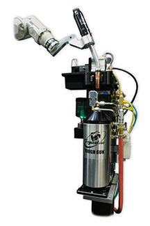
Clutches

Wire cutters
Neck inspection fixtures
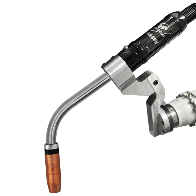
Nozzle cleaning stations and sprayers
No peripheral decision
What You Should Know About Robotic MIG Gun Clutches
What You Should Know About Robotic MIG Gun Clutches
7 Tips for Improving MIG Welding
7 Tips for Improving MIG Welding
1. Remember that the best MIG welding operator is a safe one.
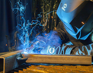
2. Do your research before you set up your equipment.
3. Make sure all of your connections are sound before getting started.
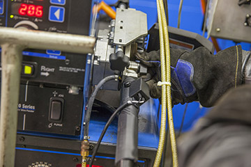
4. Select the proper drive roll and tension setting to effectively feed wire.
5. Use the correct contact tip recess for the application.
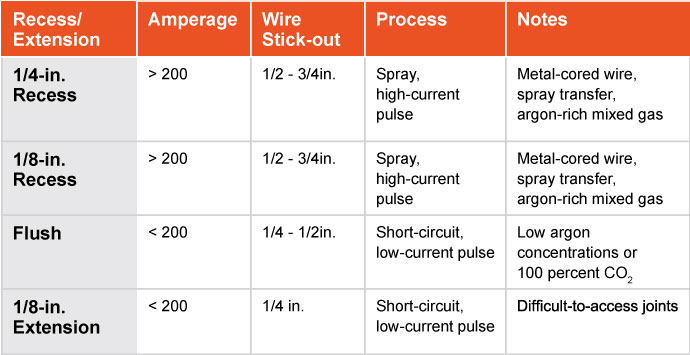
6. Use the shielding gas best suited to your wire.
7. Keep the wire directed at the leading edge of the weld pool.
Common Causes and Solutions to GMAW Gun Overheating
Common Causes and Solutions to GMAW Gun Overheating
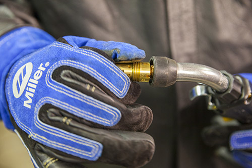
This article has been published as an exclusive with Practical Welding Today on thefabricator.com. To read the entire story, please click here.
Through-Arm Robotic MIG Guns: Top 10 Things to Consider
Through-Arm Robotic MIG Guns: Top 10 Things to Consider
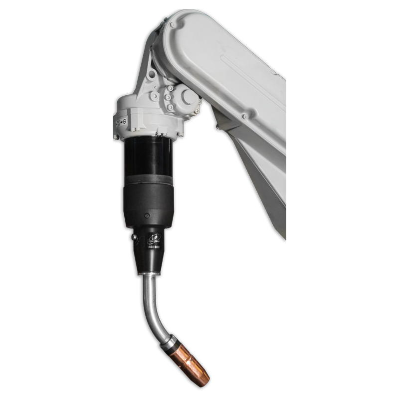
1) Look for a gun that offers good power cable rotation.
2) Look for power cables constructed of durable components and materials.
3) Select the proper amperage of gun.
4) Identify whether the robot has collision software.
5) Consult the manufacturer’s instructions when installing a through-arm robotic MIG gun.
6) Be sure the power cable position is correct and avoid making it too taut.
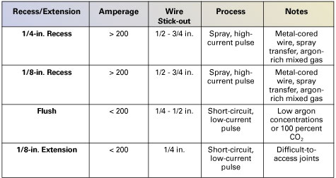
7) Always install the stud into the front housing before bolting the front end onto the robot wrist.
8) Position the wire feeder close enough to the power cable that it will not be unnecessarily stretched.
9) Regularly conduct preventive maintenance and check for clean, secure connections.
10) Visually inspect consumables and the gun on a regular basis for signs of spatter.
Best Practices and Troubleshooting Tips to Optimize Robotic Welding
Best Practices and Troubleshooting Tips to Optimize Robotic Welding
This article has been published as a web-exclusive on thefabricator.com. To read the entire article, provided by Ryan Lizotte, Tregaskiss field technical support specialist, please click here.
Preventive Maintenance Helps Optimize MIG Gun Performance
Preventive Maintenance Helps Optimize MIG Gun Performance
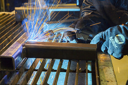
Proper inspection
Liner

Consumables
Final thoughts
Criteria for Selecting a MIG Gun
Criteria for Selecting a MIG Gun
What’s the right amperage?
Water- versus air-cooled

Heavy- versus light-duty
Fume extraction guns
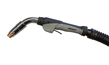
Other considerations: Cables and handles
Conclusion
Ways to Get the Most Out of Your MIG Gun Consumables
Ways to Get the Most Out of Your MIG Gun Consumables
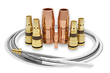
Nozzles
Contact Tips and Gas Diffusers
Cables
Correct Contact Tip Recess Can Improve Welding Efficiency
Correct Contact Tip Recess Can Improve Welding Efficiency
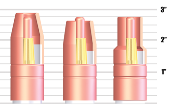
The impact on weld quality
Types of contact tip recess
Determining the correct recess
Additional information: Select quality tips
Robotic Welding Can Offer Benefits for Smaller Shops
Robotic Welding Can Offer Benefits for Smaller Shops
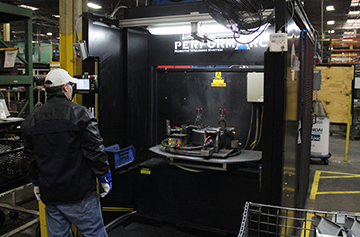
Benefits of robotic welding
Key considerations
Justifying expenses to management or ownership
Physical space and facility modifications
Part design
Part workflow
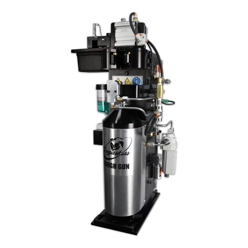
Weld cell supervision and training
Advancements can make it easier
Become more competitive with robotic welding
Proper Storage of MIG Guns and Consumables
Proper Storage of MIG Guns and Consumables
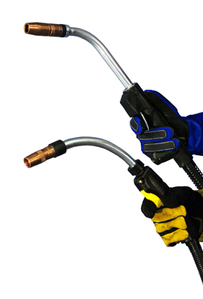
Common mistakes
Tips for MIG gun storage
Consumables storage and handling
Small steps for success
Selecting the Right Size Contact Tip
Selecting the Right Size Contact Tip
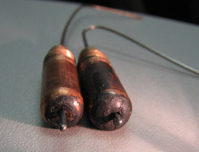
This article has been published as a web-exclusive on thefabricator.com. To read the entire story please click here.
What’s Changing? Trends in Semi-Automatic MIG Guns
What’s Changing? Trends in Semi-Automatic MIG Guns
Building in features
Reducing fume
Configuring a MIG gun
Other trends
Optimizing the Robotic Welding Process with the Right GMAW Gun
Optimizing the Robotic Welding Process with the Right GMAW Gun
Making the right choice

Choosing proper components
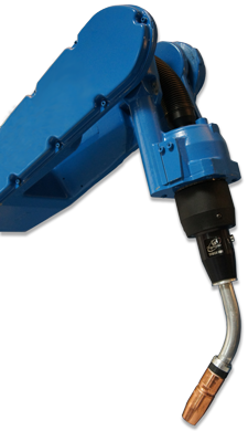
Maintaining tool center point
Adding to welding performance
Robotic GMAW gun maintenance
Tips for Choosing the Right Contact Tip
Tips for Choosing the Right Contact Tip
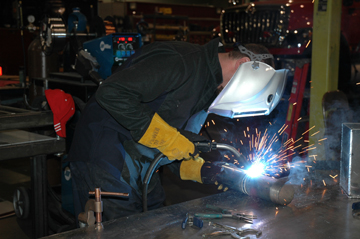
Selecting the right material and bore size
Understanding contact tip recess
Recess/Extension Amperage Wire Stick-Out Process Notes 1/4-in. Recess > 200 1/2 – 3/4in. Spray, high-current pulse Metal-cored wired, spray transfer, argon-rich mixed gas 1/8-in. Recess > 200 1/2 – 3/4in. Spray, high-current pulse Metal-cored wired, spray transfer, argon-rich mixed gas Flush < 200 1/4 – 1/2in. Short-current, low-current pulse Low argon concentrations or 100 percent CO2 1/8-in. Extension < 200 1/4 in. Short-current, low-current pulse Difficult-to-access joints Extending contact tip life
Water-Cooled Robotic MIG Guns Can Reduce Consumable Costs and Downtime
Water-Cooled Robotic MIG Guns Can Reduce Consumable Costs and Downtime
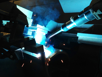
Understanding water-cooled MIG guns
Selecting a water-cooled robotic MIG gun
Maintenance and usage tips
Consider the return on investment
Trends Associated with Robotic Welding Guns
Trends Associated with Robotic Welding Guns
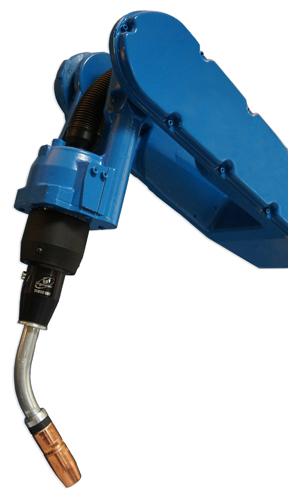
The through-arm benefits
Increased cable durability, simplified replacement
Utilizing solid mounts
Creating more space, better joint access
More cooling options
Adding the extras
More to come
5 Things to Know About Robotic MIG Guns
5 Things to Know About Robotic MIG Guns
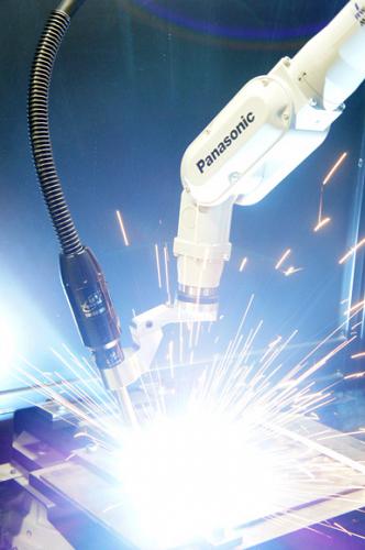
This article has been published as a web-exclusive on thefabricator.com. To read the entire story by Tregaskiss technical support specialist, Tom Whitter, please click here.
Money-Saving Tips for MIG Guns
Money-Saving Tips for MIG Guns
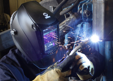
Tip No. 1: Protect the assets
Tip No. 2: Select the right neck
Tip No. 3: Perform regular inspections
Tip No. 4: Trim the liner properly
Tip No. 5: Select the best cable length for the job
Tip No. 6: Invest in consumables
Which is the Right MIG Gun? Tips for Making the Selection
Which is the Right MIG Gun? Tips for Making the Selection
Light- versus heavy-duty MIG guns
Air- versus Water-Cooled
Understanding and Extending Contact Tip Life
Understanding and Extending Contact Tip Life
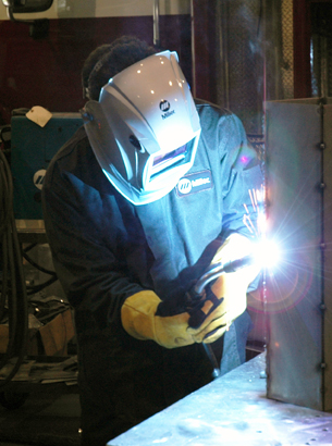
Types of contact tip failure
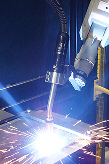
Rectifying contact tip failure
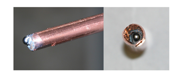
• Properly selecting and installing the MIG gun liner
• Using shorter power cables when possible
• Eliminating loops or kinks in the power cable
• Using dust covers to protect the wire from contaminants that could clog the contact tip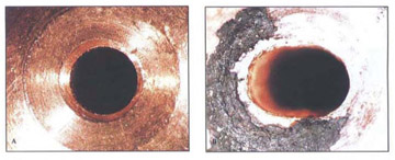
The value of extending contact tip life
Tips for Making a MIG Gun Last on the Jobsite
Tips for Making a MIG Gun Last on the Jobsite
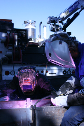
Choose a gun to fit the application
Maintaining the gun
Regular and basic care and maintenance can help extend welding equipment life on a jobsite. Simple steps such as ensuring all connections are tight and in good working order and that the weld ground is good can help produce results every day. Inspection of the MIG or flux-cored gun, equipment and consumables every time the machine is started can keep things running smoothly and reduce unplanned downtime, which helps reduce costs, extend consumable life and improve welding performance. 
![]()
![]()