Tips to Optimize the Robotic Weld Cell

Companies invest in robotic welding systems to improve productivity and gain efficiencies in their operation. But if the weld cell layout is not optimized, it can negatively impact those goals — along with the quality of the completed welds.
Poor cell layout can create a bottleneck in the process or result in parts not being properly welded —problems that cost time and money in the long term.
When considering proper layout for a robotic weld cell — whether it’s a pre-engineered cell or a custom cell —gun and consumable selection, robot reach, parts flow in and out of the cell, and weld sequencing are all important.
Pre-engineered or custom welding cell?
Proper weld cell layout is important for both pre-engineered robotic welding systems or a custom-designed system. Determining which option is right hinges on several factors.
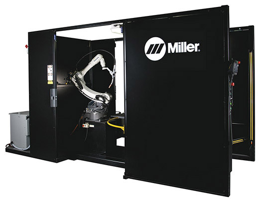
A pre-engineered robotic welding cell is designed for welding specific parts in a certain size range. Pre-engineered cells offer benefits for easy and fast installation and a much lower first cost, but they do have their limitations regarding the type and size of parts that can be welded. Part size is often the key determining factor when choosing between the two systems.
If there isn’t a pre-engineered weld cell available to fit the parts — perhaps there is a reach or weight capacity issue — then a custom robotic weld cell is the better option. Custom cells have a higher initial cost and typically a longer lead time for design and installation, but the upside is they can be customized to meet specific needs.
When installing either type of robotic weld cell, the system integrator should be involved in planning and testing to ensure cell layout is optimized for the application.

Choosing the right gun and nozzle
Having the right gun is a critical factor that can help reduce or eliminate the sources of common problems in the weld cell. Gun choice should not be an afterthought in robotic welding applications. The gun must have proper access and be able to maneuver around fixturing in the weld cell. Different choices in gun types and in consumables can help in achieving this.
Robotic welding systems are available in two styles: through-arm or conventional. Through-arm systems are gaining popularity, and most through-arm robots allow for mounting either type of gun — providing more options and flexibility depending upon the needs of the application.
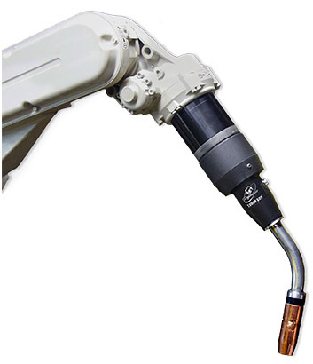
As the name suggests, the power cable assembly of a through-arm MIG gun runs through the arm of the robot as opposed to over the top of it like in a conventional gun. Because of this design, the through-arm gun style is often more durable, since the power cable is protected. However, because conventional guns can be used on either type of system — a through-arm or a conventional robot — they can sometimes offer greater flexibility, and can be used with more robot makes and models. Consider which type of gun provides the best access to the welds when making the selection.
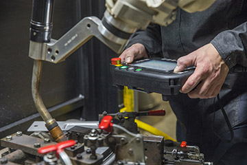
With conventional robotic welding systems especially, proper cable management is important. Once the hardware is installed and the system is set up — but before full production begins — be sure to do a test run or two through the welding sequence to determine how the gun cable moves and if it gets caught on tooling.
Another choice in selecting a gun is air-cooled versus water-cooled. This essentially comes down to the required duty cycle. The base material thickness, weld length and wire size all help determine the necessary duty cycle. Water-cooled guns are typically used in manufacturing heavy equipment and in the case of long cycle times and large wire diameters.
Once the system type and gun is chosen, it’s all about proper fit and function of the gun. It’s critical to ensure the robot arm can access all the welds — ideally in one position with one neck if possible. If not, different neck sizes, lengths and angles — and even custom necks — as well as different consumables or mounting arms can be used to improve weld access.
The choice of nozzle is another important consideration, since it can greatly hinder or improve access to the weld in a robotic cell. If a standard nozzle is not providing the necessary access, consider making a change. Nozzles are available in varying diameters, lengths and tapers to improve joint access.
While many companies like to choose a nozzle with the smallest outside diameter available, it may be necessary to size the nozzle up to avoid spatter buildup and loss of shielding gas coverage. A nozzle with a 5/8-inch bore or larger is recommended because it allows the most access.

Key considerations for proper layout
Choosing the right gun is tied closely to proper weld cell layout — since different sizes and lengths of guns and nozzles can improve or hinder reach to the welds. However, there are also many other factors involved in proper weld cell layout. Think of weld cell layout as the footprint of the entire process. Some important issues to keep in mind:
- Robot reach: It’s critical to match the size of the part being welded with the reach of the robot. A small robot welding on a very large part won’t work well, and a large robot shouldn’t be welding on a very small part. The robot must have the capability and position to reach all the areas on the part that require welding. If there is a weld on the edge of the reach envelope, for example, it might force a company to sacrifice optimal gun angle or work angle to reach that weld. This can impact weld quality, resulting in potential rework and added costs. It can also lead to premature gun or cable failure, if the robot is constantly trying to access a weld that isn’t accessible in the configuration. Many robotic welding cells mount the robot on a riser for better access to the part. Pay attention to proper riser height to optimize the access of the arm to the welds.
- Size and weight capacity: To ensure proper operation, the size and weight capacity of the positioners in the robotic weld cell must factor in not only the weight of the part, but also the weight of the tooling. Undersizing the positioner or weight capacity of the cell is a common mistake. To address this, design the cell for the heaviest part to be welded. Consider the project scope to ensure the welding system always has the capacity to handle the heaviest part in the operation.
- Material flow: The flow of material in and out of the weld cell, in addition to the sequencing of the welding process, are key in determining the right layout and positioning. Understand the material flow to the robot, how the material will be presented to the robot, and then how that welded component will be removed from the cell and moved to the next step in the operation. The weld sequence should be planned in advance, to ensure the robot can reach all the welds with the gun configuration being used.
- Test it with modeling: Software programs that allow virtual modeling or simulation of the weld cell provide the ability to test the many factors involved in proper robotic weld cell layout — from gun and nozzle choice to material flow. Take the time to simulate the weld cell layout and welding process during development. This helps determine which product and positions are needed — and helps avoid issues that could arise later once the weld cell is installed and running. In modeling, consider the components, gun, positioner, tooling, arm movements and the part itself. All these pieces must fit together and work properly to ensure the desired results. The beauty of offline programming and 3D modeling is that these components and factors can be tested virtually, without wasting materials or consumables. It’s better to prepare and prevent problems — rather than face repairs later.
The right choices enhance productivity and quality
Weld cell layout and the chosen components that fit inside have a significant impact on productivity, efficiency and quality of the finished welds. Weld cell layout that is not optimized can even harm the tooling or consumables, and result in increased time and money spent on maintenance and repair.
Protect the robotic weld cell investment by taking the time at the start of the process to test proper cell layout and equipment — to help ensure the end results and productivity gains being sought.


