
How To Install the TT3-500 TOUGH GUN Sprayer onto the TOUGH GUN TT3 Reamer
The following images and instructions detail the installation of the TT3-500 TOUGH GUN® Sprayer onto the TOUGH GUN TT3 Reamer.
- Open the box and inspect the items for any noticeable damage to the parts during shipping.
- The TT3-500 Sprayer should only be installed onto a TOUGH GUN TT3 Reamer (analog or Ethernet model). Other versions of the TOUGH GUN Reamer may require substantial modification to the reamer frame.
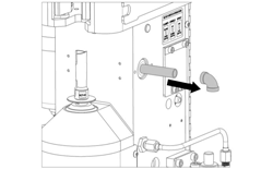
- Remove any air fittings that are attached to the main air supply line into the reamer (see Figure 1).
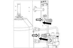
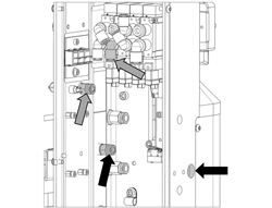
- Remove the bulkhead fittings from the stainless steel hard lines and secure them into the reamer frame in the correct holes. The quick-connect fittings will have to be removed from the bulkhead fittings first (see Figure 2).
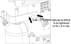
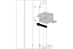
- Remove the stainless steel hard lines from the spray head and set them aside for the moment. Take the sprayer bracket along with the two M5x.8×16 SHCS (apply threadlocker to threads) and attach the bracket to the reamer (see Figure 3).
- Install the two 90-degree brass elbow fittings into the bulkhead fittings on the frame (all air fittings require thread sealant prior to installation).
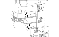
- Install both stainless steel hard lines onto the brass elbows located on the frame and the spray head (see Figure 4).
- Reinstall any air fittings on the air supply line as needed.
- Open the rear cover of the reamer and expose the bulkhead fittings that were just installed (removal of the circuit board is necessary – see OM-TT3). Taking the two quick-connect fittings, install them into the bulkhead fittings (see Figure 5).
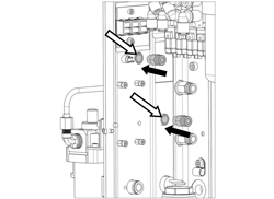
- Connect the 4-inch piece of tubing from the top quick connect fitting to the second valve from the left on the valve pack assembly (see gray arrows in Figure 6). Connect the 9.5-inch piece of tubing on the bottom quick-connect fitting and route it out through the hole on the opposite side of the frame (see black arrows in Figure 6).
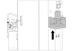
- Install the Sprayer Check Valve Bracket to the side of the reamer with the two M6x1x16 SHCS (included in the kit). Apply threadlocker to threads and torque to 50 ± 5 in.-lbs. (see Figure 7).
- Take the tubing that was routed through the frame and connect it to the check valve quick-connect fitting. Route the two wires through the same hole and into the frame of the reamer. The sheathing should be protecting the wires where they come through the frame. Using the two M4x.7×12 SCHCS (included in the kit) – threadlocker applied to threads – attach the Check Valve to the Sprayer Bracket. (see Figure 8).
- On the inside of the reamer, find the wires from the sprayer check valve.
- If your reamer is installed with factory Nichifu connectors on the terminal block:
- Connect the wires to their mating connectors.
- If there are no Nichifu connectors on the terminal block:
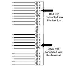
- Cut the connectors off of the check valve wires and connect them to the “O” terminals on the terminal block. The wires will be connected in the “O” terminals that correspond to their respective wire colors (see Figure 9).
- If your reamer is installed with factory Nichifu connectors on the terminal block:
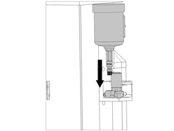
- Close the rear cover and connect the reservoir to the check valve (see Figure 10).